Figures
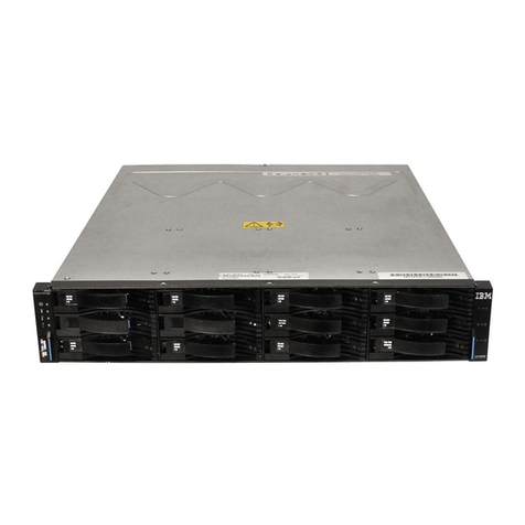
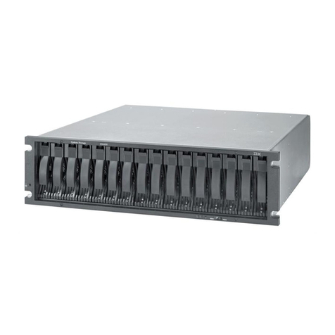
1. DS3950 hot-swap drive bays .......7
2. Back view of Model 94H; controllers with four
total Fibre Channel host channels .....10
3. Back view of Model 98H; controllers with two
Fibre Channel host channels and two iSCSI
host channels ............11
4. Power supply and fan unit components for the
DS3950 ..............14
5. Power supply and fan unit and airflow 14
6. Backup battery unit ..........15
7. SFP module and fiber-optic cable .....17
8. DS3950 dimensions ..........20
9. DS3950 airflow ...........22
10. Example of cold aisle/hot aisle rack
configuration ............25
11. Example of DS3950 serial number, machine
type, and model number location .....28
12. Front rack mounting template ......33
13. Rear rack mounting template ......34
14. Installing the support rails .......35
15. Removing and replacing a controller ....38
16. Removing a power supply and fan unit 39
17. Removing an E-DDM CRU .......39
18. Installing the DS3950 .........41
19. Securing the DS3950 to the rack cabinet 41
20. Removing and replacing a controller ....42
21. Replacing a power supply and fan unit 43
22. Replacing an E-DDM .........44
23. Storage subsystem seven-segment enclosure
IDs...............46
24. Bending and looping specifications for
fiber-optic cables ...........48
25. SFP module and protective cap ......50
26. Installing an SFP module into the host port 50
27. Unlocking the SFP module latch - plastic
variety ..............51
28. Unlocking the SFP module latch - wire variety 51
29. LC-LC Fibre Channel cable .......52
30. Removing fiber-optic cable protective caps 53
31. Inserting an LC-LC Fibre Channel cable into
an SFP module ...........53
32. LC-LC Fibre Channel cable lever and latches 54
33. Removing the LC-LC Fibre Channel cable 54
34. Example of a redundant drive channel pair 56
35. DS3950 storage subsystem ports and
controllers .............58
36. Cabling for one DS3950 and one storage
expansion enclosure..........59
37. Cabling for one DS3950 and two storage
expansion enclosures .........60
38. Incorrect cabling of one DS3950 and two
storage expansion enclosures.......61
39. Cabling for one DS3950 and three storage
expansion enclosures .........62
40. Cabling for one DS3950 and four storage
expansion enclosures .........63
41. Cabling for one DS3950 and up to six storage
expansion enclosures .........64
42. Cabling for one DS3950 and up to six storage
expansion enclosures .........66
43. Cabling for one DS3950 and two or more
storage expansion enclosures in a mixed
environment ............67
44. DS3950 drive ports connected to EXP810 ESM
ports labeled 1B ...........69
45. Cabling for one DS3950 and one EXP395
storage expansion enclosure .......70
46. One DS3950 and two EXP395 storage
expansion enclosures behind a pair of DS3950
drive ports .............71
47. One DS3950 and three EXP395 storage
expansion enclosures behind a pair of DS3950
drive ports .............72
48. One DS3950 and four EXP395 storage
expansion enclosures behind a pair of DS3950
drive ports .............74
49. One DS3950 and a maximum of six EXP395
storage expansion enclosures behind a pair of
DS3950 drive ports ..........76
50. Ethernet and serial port locations on DS3950 79
51. Host-agent (in-band) managed storage
subsystems.............81
52. Direct (out-of-band) managed storage
subsystems.............82
53. Location of host cables on RAID controllers on
the DS3950.............83
54. Cabling diagram for two redundant host
connections ............84
55. Examples of redundant host direct attached
Fibre Channel SAN configurations .....86
56. Example of a single SAN fabric configuration 86
57. Example of a dual SAN fabric configuration 87
58. Example of two storage subsystems in a dual
SAN environment ..........87
59. Example of a two-cluster configuration 88
60. Example of a single-host, multiple-port
configuration ............89
61. Example of a multiple-host, multiple-port
configuration ............89
62. Example of iSCSI and Fibre Channel hosts,
multiple-port configuration .......90
63. Example of an incorrect configuration:
Single-host, iSCSI and Fibre Channel ....91
64. Example of a multiple-host, multiple-port,
multiple-switch configuration ......92
65. Power supply and fan unit LEDs .....102
66. Front LEDs and controls ........103
67. Battery unit LEDs ..........104
68. Model 94H: LEDs, controls, and connectors of
controllers with two standard Fibre Channel
host expansion channels ........105
© Copyright IBM Corp. 2009, 2012 vii
