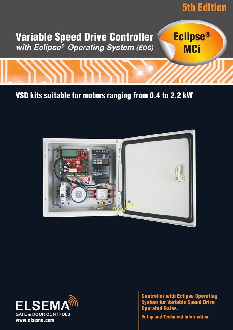
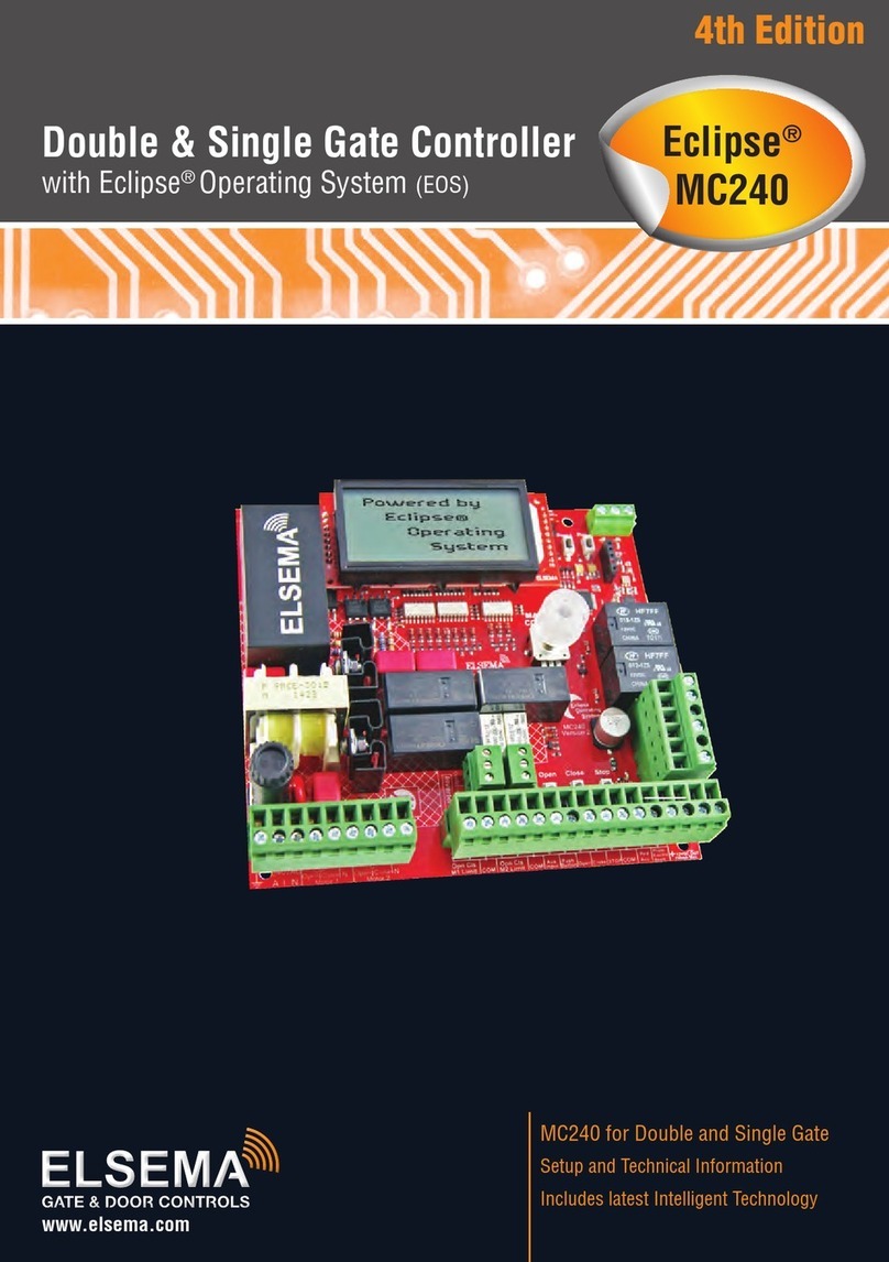
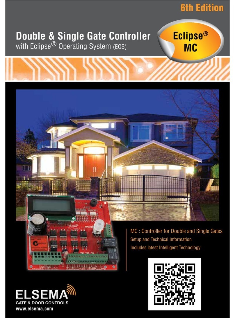
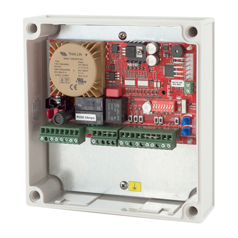
Elsema Eclipse MCS User guide

www.elsema.com
MCS : Motor Controller Single Gates
Setup and Technical Information
Includes latest Intelligent Technology
Motor Controller Single Gate
with Eclipse Operating System (EOS)
3rd Edition
®Eclipse®
MCS

All installations and testing must be done only after reading and
understanding all instructions carefully. All wiring should be done
only by trained technical personnel. Failing to follow instructions
and the safety warnings may result in serious injury and/or damage
to property.
Elsema Pty Ltd shall not be liable for any injury, damage, cost,
expense or any claim whatsoever to any person or property which
may result from improper use or installation of this product.
Risk in the goods purchased shall unless otherwise agreed in
written pass to the buyer upon delivery of the goods.
Any figures or estimates given for performance of goods are based
upon the company’s experience and is what the company obtains
on tests. The company will not accept liability for failure to comply
with the figures or estimates due to the nature of variable conditions
affecting for example Radio Remote Controls.
Please keep this setup instruction for future reference.
Installed by: _______________________________________
Service date: ______________________________________
Important warning and safety instructions
2
Gate & Door Controller with Eclipse®Operating System (EOS)

Index
Features ..............................................................4
Description..........................................................4
Part Number........................................................5
Menu Structure ............................................... 6-7
Connection Diagram ...........................................8
Supply and Motor Inputs ....................................9
Limit Switches...................................................10
Setup i-Learning Steps......................................11
Menu 1 – Auto Close........................................12
- Normal Auto Close...................................12
- Auto Close with Photoelectric Trigger ......12
- Auto Close after Power Restored ��������������13
- Auto Close Only when
Fully Opened............................................13
Menu 2 – Pedestrian Access Features ........ 13-14
Menu 3 – Input Functions.................................14
Menu 4 – Photoelectric Beam...........................15
Menu 5 – Relay Output Functions.....................16
- Lock/Brake Output....................................17
- Courtesy Light..........................................17
- Service Call Output ..................................18
- Strobe or Warning Light...........................18
Menu 6.1 – Lock/Brake Output Modes..............19
- Open Lock/Brake Activation .....................19
- Close Lock/Brake Activation.....................19
- Open Pre-Lock/Brake Activation...............19
- Close Pre-Lock/Brake Activation..............19
Menu 6.2 – Courtesy Light Output Mode..........20
Menu 6.3 – Strobe (Warning)
Light Output Mode.........................20
- Pre-Open Strobe Light Activation.............20
- Pre-Close Strobe Light Activation ............20
Menu 6.4 – Service Call Output Mode..............21
Menu 7 – Special Features................................22
- Remote Control Open Only.......................22
- Holiday Mode...........................................22
- Energy Saving Mode ................................22
- Automatic Stop / Open on Closing...........22
- Receiver Channel 2 Options .....................23
- Press and Hold on Open & Close Inputs..23
Menu 8 – Motor Obstruction
Detect Margins..................................23
- Margin Example .......................................23
Menu 9 – Motor Speed, Slow Speed
Area and Reverse Time......................24
- Open and Close Speed.............................24
- Slow Speed ..............................................24
- Slow Speed Area ......................................24
- Obstruction Stop Reverse Delay Time ......24
Menu 10 – Anti-Jam, Electronic Braking and
Open/Close Obstruction Operation .25
Menu 11 – i-Learning.......................................26
Menu 12 – Password........................................26
Menu 13 – Operational Records........................26
- Event History��������������������������������������������26
- Displays Gates/Doors Operations............. 26
Menu 14 – Tools...............................................27
- Battery Type..............................................27
- Set the Supply Voltage .............................27
- Resets Controller & Test Inputs................27
- Travel Timer for Slip Clutch Motors..........27
- Slow Speed Ramp Down Time .................27
Accessories.......................................................28
- Battery Charger and Solar Applications....28
- Backup Batteries.......................................28
- Keyring Remotes & Photoelectric Beams .29
- Strobe Lights............................................29
PentaFOB®Programming Instructions..............30
3
www.elsema.com

Description
Features
›Lithium-ion and lead acid battery charger
›Suitable for single swing and sliding gates
›Single motor operation
›Eclipse Operating System (EOS)
›Motor soft start and soft stop
›Slow speed and force adjustment
›Large 4-line LCD to indicate controllers status
and setup instructions
›1-Touch control for easy setup
›Various inputs, push button, open only, close
only, stop, pedestrian and photoelectric beam
›Supports limit switch inputs or mechanical stops
›Adjustable auto close and pedestrian access
›Adjustable lock and courtesy light outputs
›Variable photoelectric safety beam functions
›12 Volt DC Output to power accessories
›Service counters, password protection, holiday
mode and many more features
The Motor Controller Single (MCS) is not just the next generation but the industry game changer. We
wanted to create a controller that is simple to use and does just about any feature required in the gate
and door industry. The MCS is not just the next generation but the “Next Transformation” in the gate and
door industry creating an Eclipse over previously developed motor controllers.
This new intelligent motor controller is the best match for your automatic gate or door motors.
The MCS’s Eclipse® Operating System (EOS) is a user friendly menu driven system that uses the 1-touch
button to control, setup and run automatic gates, doors and barriers. It uses a large 4-line LCD screen
showing live reading of the motor performance and status of all inputs and outputs.
The intelligent controller was built from the ground up, based on customer feedback and using todays
technology. With its rich functions, consumer friendly price and with the focus during development
being ease of use and setup makes this controller the ultimate board to control your motors.
Elsema’s easy options to add remote controls or any type of photoelectric beams makes for a very user
friendly approach, while avoiding the lockdown approach to accessories.
The control cards are available with an IP66 rated plastic enclosure for outdoor installations or the card
only.
4
Gate & Door Controller with Eclipse®Operating System (EOS)

MCS
MCS24E or MCS12E
Part Number:
Part No. Contents Part No. Contents
MCS Single gate and door controller
for 24 / 12 Volt motor, card only
MCS24E Single controller for 24 Volt motors includes IP66
rated plastic enclosure and transformer MCS12E Single controller for 12 Volt motors includes IP66
rated plastic enclosure and transformer
MCS24E2 Same as MCS24E plus 24 Volt 2.6Ah backup battery MCS12E2 Same as MCS12E plus 12 Volt 2.6Ah backup battery
MCS24E7 Same as MCS24E plus 24 Volt 7.0Ah backup battery MCS12E7 Same as MCS12E plus 12 Volt 7.0Ah backup battery
Solar Gates
Solar24 Solar kit for double or single gates, includes intelligent
solar charger & 24 Volt 12.0Ah backup battery Solar12 Solar kit for double or single gates, includes intelligent
solar charger & 12 Volt 12.0Ah backup battery
SP20* 20 Watt solar panel SP40* 40 Watt solar panel
MCS12E7
5
www.elsema.com

Menu Structure Press Master Control for 2 seconds to enter the menu structure
1.0
Auto Close
1.1
Auto Close Time
1.2
AC Time with PE Trig
7.1
RC Open only
7.2
Holiday Mode
4.1
Stop & Open on Close Cycle
13.1
Events History
13.2
Display Operations / Currents
2.1
PA Travel Time
2.2
PA AC Time
5.1
Relay Output 1
Lock / Brake
6.1.1: Open Lock Activation 6.2.1: Courtesy Light
6.3.1: Pre-Open Warning Light
Lock / Brake
Courtesy Light
6.1.2: Close Lock Activation
Courtesy Light
Service Call
6.1.3: Pre-Open Lock
Service Call
Strobe (Warning) Light
6.1.4: Pre-Close Lock
6.1.5: EXIT
Strobe (Warning) Light
5.2
Relay Output 2
9.1
Open Speed (%)
9.2
Close Speed (%)
12.1
Enter Password
12.2
Delete Password
14.1
Battery Type
14.2
Supply Voltage
3.1
PE Polarity
3.2
Limit Sw Polarity
8.1
Open Obstruct
8.2
Close Obstruct
10.1
Open Anti-Jam
10.2
Close Anti-Jam
6.1
Lock Output
6.2
Light Output
2.0
Pedestrian Access
3.0
Input Functions
4.0
PE Safety Beam Function
5.0
Output Functions
6.0
Output Modes
7.0
Special Features
8.0
Motor Obstruct Detect Margin
10.0
Anti-Jam / Electronic Braking
12.0
Password
9.0
Motor Speed, Slow Speed Area & Reverse Time
11.0
Travel Learn
13.0
Operational Records
14.0
Tools
EXIT PROGRAMMING
MAIN
SCREEN
PE Beam Stops Motor
on Close Cycle
6.2.2: EXIT
6
Gate & Door Controller with Eclipse®Operating System (EOS)

1.3
AC After Open Obstruct
7.3
Energy Saving
13.3
Reset Max Current Records
13.4
EXIT
2.3
PA AC Time with PE Trig
6.4.1: Service Counters
6.3.1: Pre-Open Warning Light
6.4.2: EXIT
6.3.2: Pre-Close Warning Light
6.3.3: EXIT
5.3
EXIT
9.3
Slow Speed (%)
9.4
Open Slow Speed Area
8.4
Obstruct Det Response
9.5
Close Slow Speed Area
8.5
EXIT
7.4
Automatic Stop/Open on Closing
7.5
Receiver Channel 2 Options
6.5
EXIT
4.2
EXIT
1.5
AC on Seq. Obstruct
6.4
Service Call
2.4
PA AC on Seq. Obstruct
1.4
AC After Power Restored
1.6
AC Only When Fully Open
9.6
Stop Rev Delay Time
9.7
EXIT
12.3
EXIT
14.3
Reset Factory Default
14.4
Test Inputs
3.3
Stop Input Polarity
8.3
Slow Speed Obstruct
10.3
Electronic Braking
6.3
Strobe (Warning) Light
14.5
Travel Timer for Slip Motors
7.6
Press and Hold, Open Input
7.7
Press and Hold, Close Input
7.8
Window / Louvre Mode
7.9
Reserved
PE Beam Stops Motor
on Open & Close Cycle
PE Beam Stops Motor and
Closes on Open Cycle
2.6
EXIT
2.5
PA Hold Gate
14.8
Slow Speed Ramp Down
14.6
Solar Gate Mode
14.7
Fuse Type : 10 or 15 Amps
10.4
Open Obstruction Operation
10.5
Close Obstruction Operation
10.6
EXIT
1.7
EXIT
3.4
EXIT
14.9
Magnetic Limit Switch
7.10
Exit
14.10
Exit
7
www.elsema.com

MCS Connection Diagram
2
Normally Closed
User can change
Fuse
Relay
Open Close Stop
Master
Control
AC Supply
AC Supply
AC Supply
AC Supply
AC Supply
AC Supply
DC Output +
DC Output -
AC Supply
AC Supply
Motor
Motor
AC Supply
AC Supply
Battery +
Battery -
Open Limit
Common
Close Limit
Push Button
Open
Close
Stop
Common
PED Access
Photo Beam
+ 12 VDC
- 12 VDC
Output 1 C
Output 1 NO
AC Supply : 24/12 Volts AC
Model : MCSv1
Designed by
ELSEMA
IN AUSTRALIA
Normally Closed
User can change
ELSEMA
Normally Open
User can change
Eclipse
operating
system
Powered By
Receiver
Program 2
Program 1
Antenna 1
Shield
Antenna 2
90mm
140mm
Output 2
Used with
Relay 1-12
Output Rated
at 250mA
12 or 24 Volts
AC Supply
Built-in
Receiver
8
Gate & Door Controller with Eclipse®Operating System (EOS)

Electrical Wiring - Supply, Motors and Inputs
Always switch off power before doing any wiring.
Make sure that all the wiring is completed and that the motor is connected to the control card.
Recommended wire strip length should be 12mm for all connections to the plug in
terminal blocks.
The diagram below shows the supply, motors, and inputs available and the factory default setting for each
input.
Normally Closed
User can change
Fuse
Relay
Open Close Stop
Master
Control
Open Limit
Common
Motor 1
Close Limit
Motor 1
Push Button
Open
Close
Stop
Common
PED Access
Photo Beam
AC Supply : 24/12 Volts AC
Model : MCS
Designed by ELSEMA
IN AUSTRALIA
Normally Closed
User can change
ELSEMA
Normally Open
User can change
AC Supply
AC Supply
AC Supply
AC Supply
AC Supply
AC Supply
DC Output +
DC Output -
AC Supply
AC Supply
Motor 1
Motor 1
AC Supply
AC Supply
Battery +
Battery -
12 or 24 Volts
AC Supply
9
www.elsema.com

Limit Switches
Controller with
limits connected
By default the limit switch inputs on the control card are normally closed (NC).
This can be changed to normally open (NO) during the setup steps.
Fuse
Close
Master
Control
Open Limit
Common
Close Limit
AC Supply : 24/12 Volts AC
Model : MCS
Designed by
ELSEMA
IN AUSTRALIA
AC Supply
AC Supply
Motor
Motor
Normally Closed
User can change
M
Motor 1
Fuse
Close
Master
Control
AC Supply : 24/12 Volts AC
Model : MCS
Designed by
ELSEMA
IN AUSTRALIA
AC Supply
AC Supply
Motor
Motor
M
Close
Limit
Open
Limit
Diode* Diode*
*6Amps, 50V or better diode
Controller with limits
in series with motor
If you are using limit switches make sure they are connected properly. The control card can operate
with either the limit switches connected directly to the cards terminal blocks or in series with the
motor. See the diagrams below:
10
Gate & Door Controller with Eclipse®Operating System (EOS)

1. The i-Learning setup can always be interrupted with the stop button or by pressing the Master
Control knob.
2. Enter Menu 11 to start i-Learning or new control cards will automatically prompt you to do the
i-Learning.
3. Look at the LCD and follow the instructions displayed.
4. Buzzer will indicate learning was successful. If there was no buzzer check all electrical wiring
including the power supply then go back to step 1.
5. If you hear the buzzer the gate or door is ready for use.
Setup i-Learning Steps:
11
www.elsema.com

Auto close is a feature that automatically closes the gate/door after a preset time has counted down to
zero. The control card has a normal auto close and several special auto close features each one having
its own countdown timers.
Elsema Pty Ltd recommends a photoelectric beam should be connected to the control card when any of
the auto close options are used.
If the stop button is pressed Auto Close is disabled for that cycle only. Holding the push button, open
only or photoelectric beam will not allow the auto close timers to count down.
Menu No. Auto Close Features Factory
Default
Adjustable
1.1 Normal Auto Close Off 3 - 600 seconds
1.2 Auto Close with Photoelectric Trigger Off 1 - 60 seconds
1.3 Auto Close after an Open Obstruction Off 1 - 60 seconds
1.4 Auto Close after Power Restored Off 1 - 60 seconds
1.5 Normal Auto Close on Sequential Obstructions 2 Min = Off,
Max = 5
1.6 Auto Close Only when Fully Opened Off Off/On
1.7 Exit
Menu 1 – Auto Close
1.1 Normal Auto Close
The gate/door will close after this timer has counted down to zero.
1.2 Auto Close with Photoelectric Trigger
A photoelectric beam needs to be triggered before this auto close starts counting down to close
the gate/door. If there is no photoelectric beam trigger the gate/door will not close.
1.3 Auto Close after an Open Obstruction
If the gate/door opens and hits an obstruction normally the gate/door will stop and remain in this
position. If this feature is enabled an obstruction will start the timer count down and at zero will
close the gate/door.
12
Gate & Door Controller with Eclipse®Operating System (EOS)

1.4 Auto Close after Power Restored
If the gate/door is open in any position and then there is a power failure, when power is reconnected the
gate/door will close with this timer.
1.5 Normal Auto Close on Sequential Obstructions
If the normal auto close is set and the gate/door closes onto an object the gate/door will stop and reopen.
This setting sets the amount of times the gate/door will try to auto close. After trying for the set limit the
gate/door will remain open.
1.6 Auto Close Only when Fully Opened
The auto close timer will not time out unless the gates/doors are fully opened.
Menu 2 – Pedestrian Access
There are several types of Pedestrian access modes. Pedestrian access opens the gate/door for a short
time to allow someone to walk through the gate/door but does not allow a vehicle access.
Elsema Pty Ltd recommends a photoelectric beam should be connected to the control card when any of
the auto close options are used.
Menu No. Pedestrian Access Features Factory
Default
Adjustable
2.1 Pedestrian Access Travel Time 3 seconds 3 - 20 seconds
2.2 Pedestrian Access Auto Close Time Off 0 - 60 seconds
2.3 Pedestrian Access Auto Close Time with PE trigger Off 0 - 60 seconds
2.4 Pedestrian Access Auto Close on Sequential Obstructions 2 Min = Off,
Max = 5
2.5 Pedestrian Access with Hold Gate Off Off/On
2.6 Exit
13
www.elsema.com

2.1 Pedestrian Access Travel Time
This sets the time the gate/door opens when a pedestrian access input is activated.
2.2 Pedestrian Access Auto Close Time
This sets the countdown timer for automatically closing the gate/door when a pedestrian access input is
activated.
2.3 Pedestrian Access Auto Close Time with PE Trigger
This sets the countdown timer for automatically closing the gate/door when a photoelectric beam is
triggered and pedestrian access input is activated.
2.4 Pedestrian Access Auto Close on Sequential Obstructions
If the pedestrian access auto close is set and the gate/door closes onto an object the gate/door will stop
and reopen. This setting sets the amount of times the gate/door will try to auto close. After trying for the
set limit the gate/door will remain open.
2.5 Pedestrian Access with Hold Gate
If the pedestrian access hold gate is ON and the Pedestrian access input is permanently activated the
gate will remain open in the pedestrian access position. Open input, Close input, Push Button input and
remote controls are disable. Used in Fire Exit applications.
Menu 3 – Input Functions
This allows you to change the photoelectric beam and limit switch inputs from normally closed to
normally open.
Menu No. Input Functions Factory
Default
Adjustable
3.1 Photoelectric Beam Polarity Normally Closed Normally Closed /
Normally Open
3.2 Limit Switch Polarity Normally Closed Normally Closed /
Normally Open
3.3 Stop Input Polarity Normally Open Normally Closed /
Normally Open
3.4 Exit
14
Gate & Door Controller with Eclipse®Operating System (EOS)

The photoelectric beam is placed across the gate/door and when it is broken it can operate the gate/door
to do certain functions.
Menu No. Photoelectric
Beam Feature
Factory
Default
Adjustable
4.1 Photoelectric Beam PE Beam stops and opens
gate/door on close cycle
PE Beam stops and opens
gate/door on close cycle
------------------------------------
PE Beam stops gate/door
on close cycle
------------------------------------
PE Beam stops gate/door
on open & close cycle
------------------------------------
PE Beam stops and closes
gate/door on open cycle
4.2 Exit
The factory default for the PE beam input is “normally closed” but this can be changed to normally open.
To change it go back to Menu 3.
Elsema Pty Ltd recommends a photoelectric beam should be connected to the control card when any of
the auto close options are used.
Elsema sells several different types of photoelectric beams. We stock Retro-Reflective and Through
Beam photoelectric beams.
PE24
(Through-Beam type)
Menu 4 – Photoelectric Beam
PE1500
(Polarised Retro-Reflective Type)
15
www.elsema.com

The control card has two outputs, Output 1 and Output 2. The user can change the function of these
outputs to lock / brake, courtesy light, service call or strobe (Warning) light indicator.
Output 1 is a relay output with common and normally open contacts. Factory default is lock / brake
release function.
Output 2 is an open collector output. Factory default is courtesy light function.
Menu No. Output
Function
Factory
Default
Adjustable
5.1 Output 1 Lock / Brake
Lock / Brake
------------------------------------
Courtesy Light
------------------------------------
Service Call
------------------------------------
Strobe (Warning) Light
5.2 Output 2 Courtesy Light
Lock / Brake
------------------------------------
Courtesy Light
------------------------------------
Service Call
------------------------------------
Strobe (Warning) Light
5.3 Exit
Menu 5 – Output Functions
16
Gate & Door Controller with Eclipse®Operating System (EOS)

Lock / Brake Output
This output is used to power an electrical lock or a motor brake release. The factory default for the lock/
brake release is on output 1. User can change it to courtesy light, strobe light or service call. Output 1 is
a voltage-free relay contact with common and normally open contacts. Having it voltage-free allows you
to connect either 12VDC/AC, 24VDC/AC or 240VAC to the common. The normally open contact drives
the lock/brake. See diagram below:
Courtesy Light
This output is used to power a courtesy light. The factory default for the courtesy light is on output 2.
Output 2 is an open collector output. This output is used to switch an external relay such as Elsema’s
REL12-1 which can be purchased separately. See diagram on the next page.
Relay
Open Close Stop
12VDC/AC
24VDC/AC or
240VAC Light.
12VDC/AC
24VDC/AC or
240VAC Supply.
Depends on the light
+ if DC
- if DC
Output 1 C
Output 1 NO
17
www.elsema.com

Service Call Output
Either output 1 or output 2 can be changed to service call indicator. This will trigger the output when
the software service counter is reached. Used to alert installers or owners when the gate/door is to be
serviced. Using Elsema’s G-2000 receiver allows installers or owners to get a SMS message when the
service is due.
Strobe (Warning) Light when Opening or Closing
The relay output is activated whenever the gate/door is operating. The factory default is Off. Either output
1 or output 2 can be changed to strobe (Warning) light. See diagram above.
Relay
Stop
Master
Control
Output C
Output NO
Output NC
REL12-1
REL12-1 available
separately
18
Gate & Door Controller with Eclipse®Operating System (EOS)

Menu 6.1 – Lock / Brake Output Modes
The relay output in the lock / brake mode can be configured in different ways.
Menu No. Lock / Brake Modes Factory
Default
Adjustable
6.1.1 Open Lock / Brake Activation 2 seconds 0 – 30 seconds
or hold
6.1.2 Close Lock / Brake Activation Off 0 – 30 seconds
or hold
6.1.3 Open Pre-Lock / Brake Activation Off 0 – 30 seconds
6.1.4 Close Pre-Lock / Brake Activation Off 0 – 30 seconds
6.1.5 Exit
6.1.1 Open Lock / Brake Activation
This sets the time the output is activated in the
open direction. Factory default is 2 seconds.
Setting it to Hold means the output is activated for
the total travel time in the open direction.
6.1.2 Close Lock / Brake Activation
This sets the time the output is activated in the
close direction. Factory default is off. Setting it
to Hold means the output is activated for the total
travel time in the close direction.
6.1.3 Open Pre-Lock / Brake Activation
This sets the time the output is activated before
the motor starts in the open direction. Factory
default is Off.
6.1.4 Close Pre-Lock / Brake Activation
This sets the time the output is activated before
the motor starts in the close direction. Factory
default is Off.
19
www.elsema.com

Menu 6.2 – Courtesy Light Output Mode
The relay output in the courtesy mode can be adjusted from 30 seconds to 18 hours. This sets the time
the courtesy light is activated. Factory default is 1 minute.
Menu No. Courtesy Light Mode Factory
Default
Adjustable
6.2.1 Courtesy Light Activation 1 minute 30 seconds to
18 hours
6.2.2 Exit
Menu 6.3 – Strobe (Warning) Light Output Mode
The relay output in the strobe (Warning) mode can be configured in different ways:
Menu No. Strobe (Warning) Light Mode Factory
Default
Adjustable
6.3.1 Pre-Open Strobe (Warning)
Light Activation Off 0 – 30 seconds
6.3.2 Pre-Close Strobe (Warning)
Light Activation Off 0 – 30 seconds
6.3.3 Exit
6.3.1 Pre-Open Strobe Light Activation
This sets the time the strobe light is activated before the gate/door operates in the open direction.
Factory default is Off.
6.3.2 Pre-Close Strobe Light Activation
This sets the time the strobe light is activated before the gate/door operates in the close direction.
Factory default is Off.
20
Gate & Door Controller with Eclipse®Operating System (EOS)
Other manuals for Eclipse MCS
1
Table of contents
Other Elsema Controllers manuals
