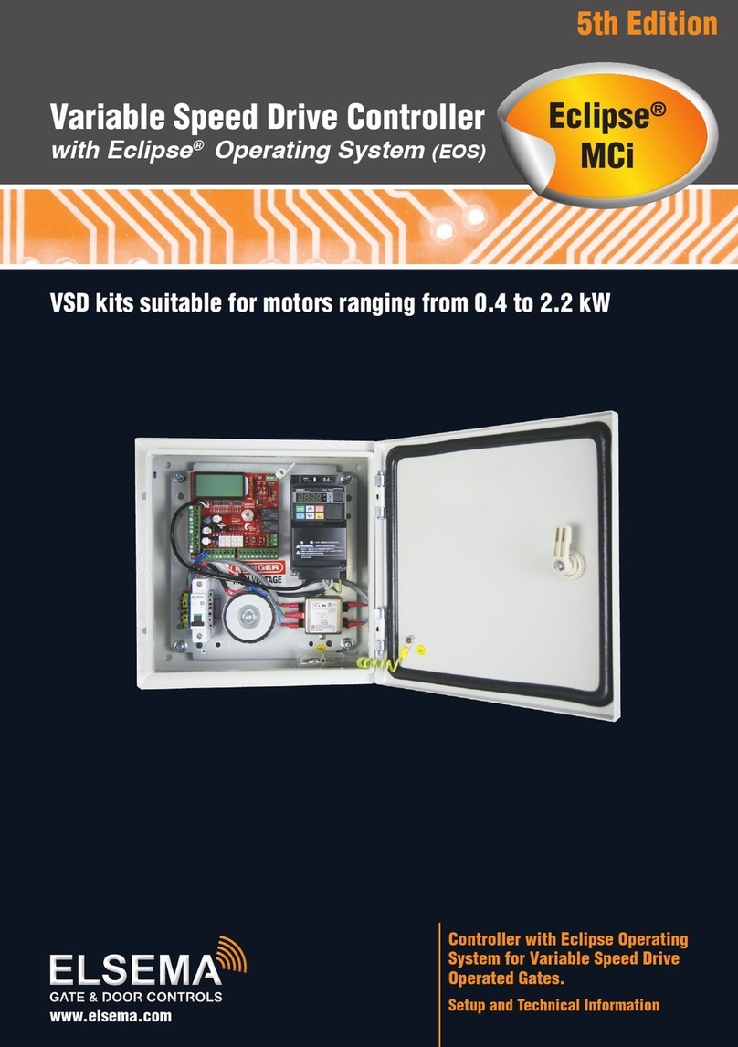
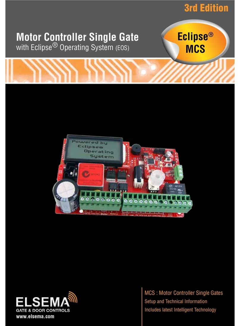
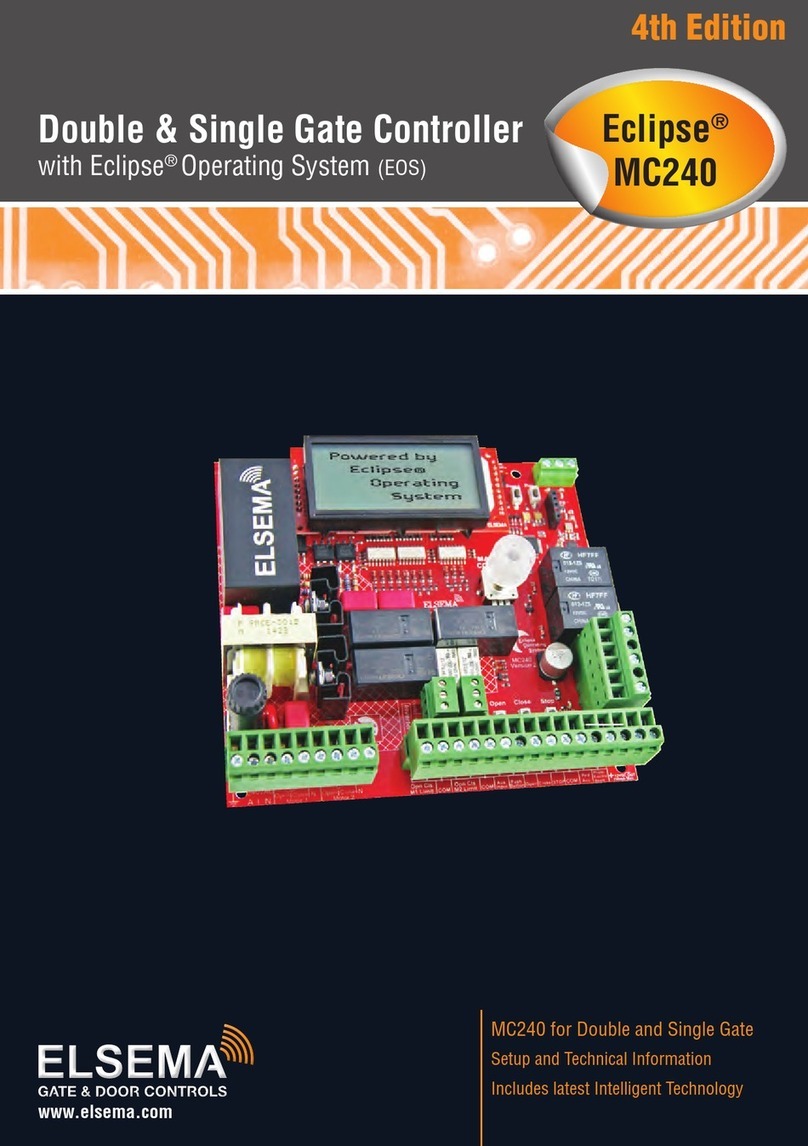
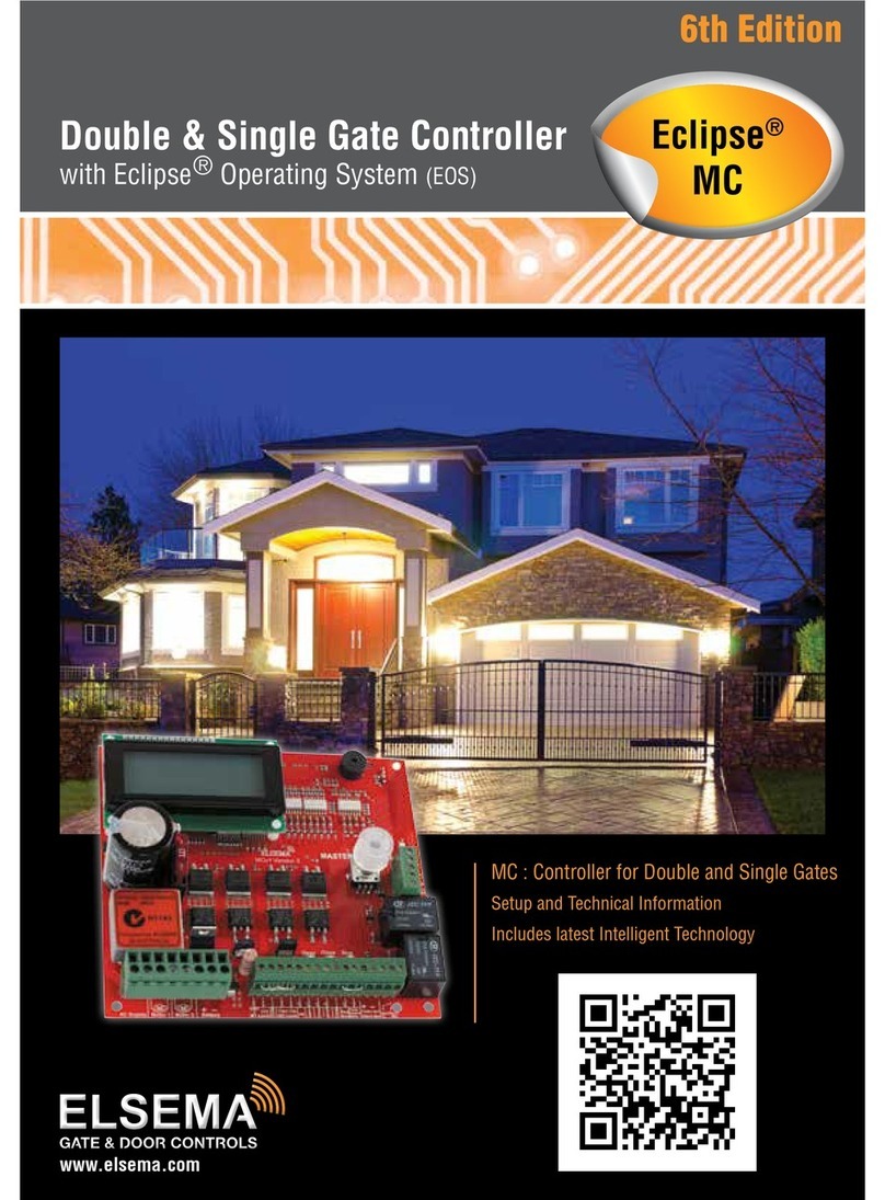
Elsema 240S1 Series User manual

Controller Card for 240VAC Motors
used on Light Commercial Doors, Industrial Roller Shutters,
Sectional Doors, Garage Doors, Sliding Doors and Swing Gates
VERSION 3
www.elsema.com
240S1
240S2

2Controller Card for 240VAC Motors
Features
• Adjustableautoclose
• Adjustableslowspeedforopenandclose
• Deadmancontrolsforopenandcloseinputs
• Automaticgroundandtraveldistancecalibration
• Photocell,pedestrianandwirelessremotecontrolinputs
• Externalkeyswitchforsafetyandsecurity(Onlyon240S2)
• SupportsNCorNOlimitswitchinputsortraveltimersetup
• Auxrelayoutputtocontrolcourtesylightsandotheraccessories
• 24VDCoutputtosupplyexternalaccessoriessuchasloopdetectors,swipecardsetc
• Toroidaltransformerforexcellentefciencyandlowleakagelossesreducingyourelectricity
consumption.DynamicPowerSavings
• Customisedmodelsavailableuponrequest,120S1and120S2forinternationalmarkets
Description
The240S1and240S2areverysimilarcardsexceptforthecardsizeandthe240S2hasakey
switchinput.Offeringtwodifferentsizesallowsthecardstobeeasilyinstalledintoexistingcasesas
replacementorupgradecards.Thesetwocardsareoneofourbestvaluedcardsonthemarket,selling
foraverycompetitiveprice,yetstillloadedwithmanyfeatures.
Thecontrolcardswerebuiltfromthegroundup,basedoncustomerfeedbackandusingtoday’s
technology.Withitsrichfunctions,consumerfriendlypriceandwiththefocusduringdevelopment
beingeaseofuseandsetupmakesthese240VACcontrolcardstheultimateboardtocontrol
yourmotors.
Atoroidaltransformerisusedtopowerthecontrolcardandcontactors.Usingatoroidaltransformer
offersthefollowingadvantages:
• Excellentefciencyandlowleakagelossesreducingyourelectricityconsumption
• Highisolationwhichprotectstheelectronicsfromnoisypowerlines
• LowmagneticeldradiationandnoacousticnoiseenablingthecontrollertopassEMCandother
stringentradiationtests
Allinstallationsandtestingmustbedoneonlyafterreadingandunderstandingallinstructionscarefully.
Allwiringsshouldbedoneonlybytrainedtechnicalpersonnel.Failingtofollowinstructionsandthe
safetywarningsmayresultinseriousinjuryand/ordamagetoproperty.
ElsemaPtyLtdshallnotbeliableforanyinjury,damage,cost,expenseoranyclaimwhatsoevertoany
personorpropertywhichmayresultfromimproperuseorinstallationofthisproduct.
Important warning and safety instructions

3www.elsema.com
Part Numbers:
Part Number Description Application
240S1E
The240S1EisenclosedinacompactIP66ratedplastic
enclosure.CaseSize:175x175x75mm
120S1E-120VACversionforinternationalmarketswith
120VACVoltage
LightCommercialDoors,Industrial
RollerShutters,SectionalDoors,
GarageDoors,SlidingDoorsand
SwingGates
240S2E
The240S2EisenclosedinaIP66ratedplasticenclosurewith
UP/DOWN/STOPexternalpushbuttons.
120S2E-120VACversionforinternationalmarketswith
120VACVoltage
LightCommercialDoors,Industrial
RollerShutters,SectionalDoors,
GarageDoors,SlidingDoorsand
SwingGates
240S2EK
The240S2EKisenclosedinaIP66ratedplasticenclosurewith
UP/DOWN/STOPexternalpushbuttonsandkeyswitchfor
extrasecurityandsafety.
120S2EK-120VACversionforinternationalmarketswith
120VACVoltage
LightCommercialDoors,Industrial
RollerShutters,SectionalDoors,
GarageDoors,SlidingDoorsand
SwingGates
240S1
The240S1controlcardonlywithboardsizeof148x92mm.
120S1-120VACversionforinternationalmarketswith
120VACVoltage
Replacementorupgradecontrollercard
for240VACMotors
240S2
The240S2controlcardonlywithboardsizeof148x120mm
andkeyswitchinput.
120S2-120VACversionforinternationalmarketswith
120VACVoltage
Replacementorupgradecontrollercard
for240VACMotors
Allthesecontrollersaresuitableformotorsupto1.5kW(2.0Hp).
Riskinthegoodspurchasedshallunlessotherwiseagreedinwrittenpasstothebuyerupondeliveryof
thegoods.
Anyguresorestimatesgivenforperformanceofgoodsarebaseduponthecompany’sexperienceand
iswhatthecompanyobtainsontests.Thecompanywillnotacceptliabilityforfailuretocomplywith
theguresorestimatesduetothenatureofvariableconditionsaffectingforexampleRadioRemote
Controls.
Pleasekeepthissetupinstructionforfuturereference.

4Controller Card for 240VAC Motors
Block Diagram
240S1

5www.elsema.com
240VAC Supply Supplyconnectiontopowerthe240S1andthemotor
Open MotorOPENdirectionterminal
Close MotorCLOSEdirectionterminal
Neutral Motorneutralterminal
Motor Capacitor Motorcapacitorterminal
Auxiliary Output Usedtoconnectalockorcourtesylight.RelayContacts,CommonandNormallyOpen
Limit Switch Open &
Common
Iflimitswitchesareusedconnectthemtothisterminal.
FactoryDefaultNormallyClosed
Limit Switch Close Iflimitswitchesareusedconnectthemtothisterminal
Push Button Usedtoconnectanexternalpushbuttontooperatethegateordoor.Normallyopeninput.
Open Only Usedtoconnectanexternalpushbuttontoopenthegateordoor.Withthisinputgateordoor
cannotbeclosed.Holdingthisinputwillpreventclosing.NormallyOpeninput.
Close Only Usedtoconnectanexternalpushbuttontoclosethegateordoor.Withthisinputgateordoor
cannotbeopened.Holdingthisinputwillpreventopening.NormallyOpeninput.
Common Commonterminalforanyoftheinputs,includingpushbutton,openonly,closeonly,stop
andpedestrianaccess.
Stop Usedtoconnectanexternalpushbuttontostopthegateordoor.Holdingthisinputwill
preventthegateordoorfromopeningorclosing.NormallyOpeninput.
Pedestrian Access Usedtoconnectanexternalpushbuttontoopengateordoorpartiallyforpedestrianaccess.
NormallyOpeninput.
Photo Electric Beam Usedtoconnectaphotoelectricbeam.FactoryDefaultisNormallyClosedinput.Usercan
changetoNormallyOpen.
DC Output 24VDC/150mA.Usetosupplyaccessories.
(UseElsemaReg12toconvertthisoutputto12VDC)
Slide Switch Usedtoaccessthecontrolcardfeatures.
Input Status LEDs Indicatesinputsstatus.
Tact Switches
TestbuttonforinputsinRUNmodeandusedtoaccessthefeaturesinprogrammode.
A=PushButton
B=OpenOnly
C=CloseOnly
D=Stop
E=PedestrianAccess
Auto Close trimpot UsedtoadjusttheAutoClosetime.
Dip Switch Usedtoaccessthecontrolcardfeatures.
Open, Close LEDs IndicatesOpeningorClosingcycle.
Enter button Usedtochangefeaturesinprogrammingmode.
Receiver UsedtoconnectElsema’sreceiverstooperatethecontrolcardwitharemotecontrol.Use
Elsema’sPentacodeseries.
Antenna Usedtoconnectanexternalantennaforthepluginreceiver.
Buzzer Indicatesthatchangeoffeatureswassuccessful.
Fuse Slowblow5Ampsfuse.Replacefusewithaslowblow10Ampsifusingamotorlargerthan
1.0kW(1.3HP).

6Controller Card for 240VAC Motors
Relay
A B C D
1
8
ON
27
6
54
3
RUN
Prog1
Prog2
E
FUSE
Open
Close
Normally Closed
User can change to
Normally Open
240Volts
AC Supply
Normally Closed
User can change
Neutral
Motor
Capacitor
Open Limit
Close Limit
Common
Push Button
Open Only
Close Only
Stop
Common
PED Access
Photo Beam
Common
Active
Neutral
Open
Close
M
Motor
Capacitor
Output C
Output NO
DC Output +
DC Output -
Manual
Auto
Common
Key Switch
Input
Earth
R
e
c
e
i
v
e
r
AntennaAntenna
Shield
148mm
120mm
Block Diagram
240S2

7www.elsema.com
240VAC Supply Supplyconnectiontopowerthe240S2andthemotor
Open MotorOPENdirectionterminal
Close MotorCLOSEdirectionterminal
Neutral Motorneutralterminal
Motor Capacitor Motorcapacitorterminal
Auxiliary Output Usedtoconnectalockorcourtesylight.RelayContacts,CommonandNormallyOpen
Limit Switch Open &
Common
Iflimitswitchesareusedconnectthemtothisterminal.
FactoryDefaultNormallyClosed
Limit Switch Close Iflimitswitchesareusedconnectthemtothisterminal.
Push Button Usedtoconnectanexternalpushbuttontooperatethegateordoor.Normallyopeninput.
Open Only Usedtoconnectanexternalpushbuttontoopenthegateordoor.Withthisinputgateordoorcannotbe
closed.Holdingthisinputwillpreventclosing.NormallyOpeninput.
Close Only Usedtoconnectanexternalpushbuttontoclosethegateordoor.Withthisinputgateordoorcannotbe
opened.Holdingthisinputwillpreventopening.NormallyOpeninput.
Common Commonterminalforanyoftheinputs,includingpushbutton,openonly,closeonly,stopandpedestrian
access.
Stop Usedtoconnectanexternalpushbuttontostopthegateordoor.Holdingthisinputwillpreventthegateor
doorfromopeningorClosing.NormallyOpeninput.
Pedestrian Access Usedtoconnectanexternalpushbuttontoopengateordoorpartiallyforpedestrianaccess.NormallyOpen
input.
Photo Electric Beam Usedtoconnectaphotoelectricbeam.FactoryDefaultisNormallyClosedinput.Usercanchangeto
NormallyOpen.
DC Output 24VDC/150mA.Usetosupplyaccessories.(UseElsemaReg12toconvertthisoutputto12VDC)
Common CommonterminalforKeySwitch(NCType)
Auto Autoterminalforkeyswitch.Motorwillbecontrolledbyremotecontrol
Manual Manualterminalforkeyswitch.MotorwillbecontrolledbyOpen,CloseandStoppushbuttons.
Tact Switches
TestbuttonforinputsinRUNmodeandusedtoaccessthefeaturesinprogrammode.
A=PushButton
B=OpenOnly
C=CloseOnly
D=Stop
E=PedestrianAccess
Slide Switch Usedtoaccessthecontrolcardfeatures.
Auto Close trimpot UsedtoadjusttheAutoClosetime.
Dip Switch Usedtoaccessthecontrolcardfeatures.
Open, Close LEDs IndicatesOpeningorClosingcycle.
Enter button Usedtochangefeaturesinprogrammingmode.
Receiver UsedtoconnectElsema’sreceiverstooperatethecontrolcardwitharemotecontrol.UseElsema’s
Pentacodeseries.
Antenna Usedtoconnectanexternalantennaforthepluginreceiver.
Buzzer Indicatesthatchangeoffeatureswassuccessful.
Fuse Slowblow5Ampsfuse.Replacefusewithaslowblow10Ampsifusingamotorlargerthan1.0kW
(1.3HP).

8Controller Card for 240VAC Motors
A B C D
87
E
Close
8
Push Button
Open Only
Close Only
Stop
Ped Access
Photo Beam
Normally Open
(NO)
Normally Closed
User can change
Common
Common
+
-
24V DC out
150mA max
Status LED's
Test buttons
Open
Close
Slow Speed or
Force adjustment
240S1
Electrical Wiring
Alwaysswitchoffpowerbeforedoinganywiring.
Makesurethatallthewiringiscompletedandthatthemotorisconnectedtothecontrol
card.Recommended wire strip length should be 10mm for all connections to
the plug in terminal blocks.
Inputs and Outputs Diagram
Thediagrambelowshowstheinputsandoutputsavailable,theirfactorydefaultsettings,statusLED’s
andthetestbuttonforeachinput.
Setup Instructions
DANGER
Mains
voltage

9www.elsema.com
7 8
A B C DE
8
Push Button
Open Only
Close Only
Stop
Ped Access
Photo Beam
Normally Open
(NO)
Normally Closed
User can change
Common
Common
+
-
24V DC out
150mA max
Status LED's
Test buttons
Common
Auto
Manual
3 position Key Switch
NC (Normally Closed)
240S2
Open, Close and Remote Control Inputs
Theopenandcloseinputsarefactorydefaultsettingtooperateaspressandhold.Thismeanstheuser
willneedtokeeppressingtheinputforthegate/doortooperate.
Theremotecontrolinputsarefactorydefaultsettingtooperateaslatching.Thismeanstheuserpresses
theremotebuttononceandthegate/doorwillfullyopenorfullyclose.
Thepressandholdandlatchingfunctionscanbechangedbyfollowingthestepsandtablebelow:
1. Setdipswitch7and8“ON”and1to6“OFF”
2. Setthemodeswitchtoprogrammode1
PTO

10 Controller Card for 240VAC Motors
3. Setdipswitch1,2,3and4asshowninthetablebelow
Dip switch 1 Dip switch 2 Dip switch 3 Dip switch 4
OpenButton On=PressandHold
Off=Latching
CloseButton On=PressandHold
Off=Latching
RemoteButton1
On=PressandHold
(Button1OpenOnly)
Off=Latching
RemoteButton2
On=PressandHold
(Button2CloseOnly)
Off=Latching
4. PresstheEnterbutton.
5. Buzzerwillbeeptoconrmthechangewassuccessful
6. SetalldipswitchesoffandthemodeswitchtoRun.
IftheremotecontrolistobeusedforOpenOnlyandCloseOnlyfunctionthenthedipswitch2should
besetoninnormalrunmode.
Orangetextindicatesfactorydefaultsetting
Stop and Reverse feature for Push Button
and Remote Control on Close Cycle
Thisfeatureisusedtodisableorenablethe
stopandreversefeatureforthepushbuttonand
remotecontrolontheclosingcycle.Factory
defaultisenabled,thereforeonclosingapush
buttonactivationwillstopthegate/doorand
automaticallyopenit.Followthestepsbelowto
disableorenablethisfeature.
1. Setdipswitch5and8to“ON”
2. Setdipswitch1to4and6,7to“OFF”
3. Setthemodeswitchtoprogrammode1.Run
LEDwillturnred
4. Pressbutton“A”todisableStopandReverse
featureorpressbutton“C”toenableStop
andReversefeature.
5. Buzzerwillbeeptoconrmthechangewas
successful
6. Setalldipswitchesto“OFF”andmode
switchtorun
Push Button Open Only
Thisfeaturechangesthefunctionofthepush
buttonto“OpenOnly”.Thepushbuttoninput
willopengate/door,pushbuttoncannotclose
gate/door.Pushbuttoninputwillbethesame
functionasopenonlyinput.Followthesteps
belowtoenableordisablethisfeature.
1. Setdipswitch5and6to“ON”
2. Setdipswitch1to4and7,8“OFF”
3. Setthemodeswitchtoprogrammode1.Run
LEDwillturnred
4. Pressbutton“A”toenablePBopenonlyor
pressbutton“C”todisablePBopenonly.
5. Buzzerwillbeeptoconrmthechangewas
successful
6. Setalldipswitchesto“OFF”andmode
switchtorun

11www.elsema.com
Relay
1234 5 6
Open Limit
Close Limit
Normally Closed
User can change to
Normally Open
Limit switch
status LED's
Photoelectric Beam Polarity
Tochangethephotoelectricbeampolarityfollowthesesteps:
1. Setdipswitch6and8“ON”
2. Setdipswitch1to5and7“OFF”
3. Setmodeswitchtoprogrammode1,therunLEDwillturnred
4. Pressbutton“A”fornormallyopenorbutton“C”fornormallyclosed
5. Buzzerwillbeeptoconrmthechangewassuccessful
6. SetmodeswitchtoRun
Limit Switch
– Internal Limit Switches
Internalmotorlimitswitchesareusually
connectedinserieswiththemotorwiresandthey
donotrequireanyconnectiontothecontrolcard.
Usetraveltimertosetupmotortraveldistances.
– External Limit Switches Connected to
the Control Card
Ifyouareusingexternallimitswitchesmakesure
theyareconnectedtothecontrolcardasshown
inthediagrambelow.Checkthelimitswitch
statusLED’sareindicatingthecorrectstatusof
thelimitswitches.LED“ON”meanslimitswitch
isactivated.
Tochangethelimitswitchpolarityfromnormally
closedtonormallyopen,followthesesteps:
1. Setdipswitch8“ON”
2. Setdipswitch1to7“OFF”
3. Setmodeswitchtoprogrammode1,therun
LEDwillturnred
4. Pressbutton“A”fornormallyopenlimitsor
button“C”fornormallyclosedlimits
5. Buzzerwillbeeptoconrmthechangewas
successful
6. SetmodeswitchtoRun

12 Controller Card for 240VAC Motors
Supply and Motor Wiring Diagram
Connectthesupplyand240VACmotorasshowninthediagrambelow.Ifthemotordoesnothavean
internalstartingcapacitortheboardhasprovisiontoconnectthecapacitor.
Warning
Makesurethatthemainspowerisalwaysswitchedoffbeforedoinganywiring.
FUSE
6
M
Active
Neutral
240Volts
AC Supply
Motor Neutral
Open Close
Motor
Capacitor
Earth
240S1E/240S2E
DANGER
Mains
voltage

13www.elsema.com
Setup Travel Timer, Slow Speed and Force
Usetraveltimersetupifoneofthefollowingapplies:
• Slowspeedisrequired.
• Forceneedstobeadjusted.
• Usinginternalmotorserieslimitswitches.
• Usinglinearmotorsormotorswithamechanicalclutch.
• Usingexternallimitswitchesandneedmorethan90secondtraveltime.
ThetraveltimercanbeprogrammedusingthePushButtoninput,RemoteControlinput,OpenOnly
ButtoninputandCloseOnlyButtoninput.
Force Adjustment
Forceadjustmentshouldbedonebeforesettingtraveltime.Traveltimesetupwillhavetobedoneagain
ifforceadjustmentischanged.
1. Closethedoor/gatefullyandpowerupthecontrolboard
2. Setdipswitch2and7“ON”
3. Setdipswitch1,3to6and8“OFF”
4. SetmodeswitchtoProgrammode1,therunLEDwillturnred
5. PresstheEnterbutton,thebuzzerwillgiveashortbeep
6. PressbuttonBorOpeninputtoopenthedoor/gate.AdjusttheOpenForceTrimpottoadjustthe
openingforceofthemotor
7. PressbuttonCorCloseinputtoclosethedoor/gate.AdjusttheCloseForceTrimpottoadjustthe
closingforceofthemotor
8. Repeatsteps6and7untiltherequiredforceisachievedinbothdirections.
9. Fullyclosethegateandproceedtotraveltimesetup
Travel Time Setup
1. Setdipswitch7“ON”only.(Swichdipswitch2“OFF”ifforcewasadjusted)
2. Setdipswitch1to6and8“OFF”
3. SetmodeswitchtoProgrammode1,therunLEDwillturnred
4. PresstheEnterbutton,theopenLEDwillstartashing
5. Pressandholdthepushbuttoninputortheremotecontrol,doorwillstartopening
6. Releasethepushbuttonorremotewhenthedoor/gatereachesthefullyopenposition
7. PresstheEnterbutton,thecloseLEDwillstartashing
8. Pressandholdthepushbuttoninputortheremotecontrol,door/gatewillstartclosing
9. Releasethepushbuttonorremotewhenthedoor/gatereachesthefullycloseposition
10.PresstheEnterbutton,thebuzzerwillbeepfor2sectoindicatelearningissuccessful
11.SetmodeswitchtoRunModeorchangedipswitchtoexitlearnmode

14 Controller Card for 240VAC Motors
Slow Speed
Inordertouseslowspeed,traveltimehastobesetup.Theslowspeedcanbeadjustedanytimeduring
setuporinnormalrunmode.Slowspeedcanbeadjustedindependentlyforopenandclose.Ifslow
speedisnotrequired,turnthebluepotsfullyclockwise.
Setup Pedestrian Access Travel Timer
Pedestrianaccessopensthegate/doorforashorttimetoallowsomeonetowalkthroughthegate/door
butdoesnotallowavehicleaccess.Thefactorydefaultpedestrianaccesstraveltimeris3seconds.To
changethedefaulttime,followthestepsbelow.
1. Closethedoor/gatefullyandpowerupthecontrolboard
2. Setdipswitch6“ON”
3. Setdipswitch1to5and7,8“OFF”
4. Setmodeswitchtoprogrammode1,therunLEDwillturnred
5. PresstheEnterbutton,theopenLEDwillstartashing
6. Pressandholdthepushbuttoninputortheremotecontrol,door/gatewillstartopening
7. Releasethepushbuttonorremotewhenthedoor/gatereachesthepedestrianaccessopenposition
8. PresstheEnterbutton,thecloseLEDwillstartashing
9. Pressandholdthepushbuttonortheremotecontrol,door/gatewillstartclosing
10.Releasethepushbuttonorremotewhenthedoor/gatereachesthefullycloseposition
11.PresstheEnterbutton,thebuzzerwillbeepfor2secondstoindicatelearningissuccessful
12.SetmodeswitchtoRunModeorchangedipswitchtoexitPedestrianAccessLearnmode
Courtesy Light and Lock Time
Dipswitch6allowsyoutosetuptheAUXrelayoutputtoeitheralightorlockoutput.
Dipswitch6“OFF”inRunmode=>AUXRelayoutputiscourtesylight
Dipswitch6“ON”inRunmode=>AUXRelayoutputislock
Courtesy Light
Courtesylighttimeisasfollows:
• Onpoweruplightisonfor60seconds
• Lightstaysonfor60secondsaftertheendofeachruncycle.
Controlling the Courtesy Light with a Remote Control
Button2oftheremotecanbesettooperatethecourtesylightbyselectingdipswitch7on.Thiswill
overridetheclosefunctionofbutton2oftheremoteifselected.

15www.elsema.com
Lock Time
Whentheauxiliaryrelayisprogrammedasalockoutputtherelayisactivatedforasettimeonthe
openingandclosingcycle.Thefactorydefaultlocktimeis2seconds.
Tochangethedefaultlocktimefollowthesesteps:
1. SetmodeswitchtoProgramMode1
2. Setdipswitch6and7“ON”
3. PressButtonAfortherequireddurationofthelocktime
4. ReleaseButtonA
5. Buzzerwillbeeptoindicatelocktimehasbeenchanged
6. Switchoffalldipswitches
7. SetmodeswitchtoRunmode
Brake
Whenenabledthisfeatureappliesbraketothegate/doorwhenitstops.Idealifthegate/doorisinstalled
inaslopingplane.Thefactorydefaultis“OFF”.
Toenablebrakefollowthesesteps:
1. SetmodeswitchtoProgramMode1
2. Setdipswitch5and7“ON”
3. Setdipswitch1to4and6,8to“OFF”
4. Pressbutton“A”toenablebrake
orpressbutton“C”todisablebrake
5. Switchoffalldipswitches
6. SetmodeswitchtoRunmode
Overrun Time
Theoverruntimeisextratimeaddedtothelearnttraveltime.Addingoverruntimecancompensatefor
windormechanicalloading.Thefactorydefaultis10sec.
Tochangeoverruntimefollowthesesteps:
1. SetmodeswitchtoProgramMode1
2. Setdipswitch5“ON”
3. Setdipswitch1to4and6,7,8to“OFF”
3. Pressbutton“A”for30seconds,“C”for10secondsor“E”for2seconds
4. Switchoffalldipswitches
5. SetmodeswitchtoRunmode

16 Controller Card for 240VAC Motors
Dip Switch Functions
Feature Dip Switch settings Description
AutoClose
Dipswitch1“ON”
ON DIP
1 2 3 4 5 6 7 8
ON
1 2 3 4 5 6 7 8
Autocloseisafeaturethatautomaticallyclosesthegate/dooraftera
presettimehascounteddowntozero.Adjusttheautoclosetrimpot
tochangetimebetween3–60seconds.
RemoteControl
OpenOnlyand
CloseOnly
Dipswitch2“ON”
ON DIP
1 2 3 4 5 6 7 8
ON
1 2 3 4 5 6 7 8
Bydefaulttheremotecontrolallowstheusertoopenandclose
thegate/doorwithbutton1.Thismodedisablesclosingforthe
remotecontrolonbutton1andmovestheclosingfunction
tobutton2oftheremotecontrol.
SecurityClose
Dipswitch3“ON”
ON DIP
1 2 3 4 5 6 7 8
ON
1 2 3 4 5 6 7 8
Gate/doorwillcloseassoonasthevehiclehas
passedthroughthephotoelectricbeam.
PhotoelectricBeam
Dipswitch4and5“OFF”
ON DIP
1 2 3 4 5 6 7 8
Photoelectricbeamstopsandopensgate/dooronclosecycle
PhotoelectricBeam
(SpecialSecurityClose)
Dipswitch4“ON”and5“OFF”
ON DIP
1 2 3 4 5 6 7 8
ON
1 2 3 4 5 6 7 8
Photoelectricbeamstopsgate/dooronclosecycle
PhotoelectricBeam
Dipswitch4“OFF”and5“ON”
ON DIP
1 2 3 4 5 6 7 8
ON
1 2 3 4 5 6 7 8
Photoelectricbeamstopsgate/dooronopenandclosecycle
PhotoelectricBeam
Dipswitch4and5“ON”
ON DIP
1 2 3 4 5 6 7 8
ON
1 2 3 4 5 6 7 8
Photoelectricbeamstopsandclosesgate/dooronopencycle
AuxiliaryRelay
CourtesyLightor
Lock
Dipswitch6“ON”
ON DIP
1 2 3 4 5 6 7 8
ON
1 2 3 4 5 6 7 8
Dipswitch6“OFF”-AUXRelayoutputiscourtesylight
Dipswitch“ON”-AUXRelayoutputislock
AuxiliaryRelay
2ChannelCourtesy
Light
Dipswitch7“ON”
ON DIP
1 2 3 4 5 6 7 8
ON
1 2 3 4 5 6 7 8
Button2oftheremotewillswitch“ON”thecourtesylightfor60secs
AuxiliaryRelay
StrobeLight
Dipswitch8“ON”
ON DIP
1 2 3 4 5 6 7 8
ON
1 2 3 4 5 6 7 8
AuxRelayoutputisstrobelightoutput.Relayisonlyactivated
whenthegate/doorismoving.Dipswitch8“ON”overrides
courtesylightandlock.

17www.elsema.com
InAUTOmodetheOpenandClosebuttononthefrontofthecasearedisabled.
OFF:WhenthekeyisintheOFFposition,thecontroller(motor)doesnotwork.Thepushbuttonsand
thewirelessremotesaredisabled.
MANUAL:WhenthekeyisintheMANUALpositionthecontroller(motor)willonlyoperatewiththe
pushbuttonsthatareonthefrontpanel.Wirelessremotecontrolsaredisabled.
Test Buttons and status LED’s
Eachinputhasabuilt-intestbuttonandastatusLED.Thetestbuttonsarelocatedbehindtheterminal
blocksofeachinput.ThestatusLEDisnexttotheinputtestbuttons.
Fuse
Thestandardfuseincludedwiththeboardisaslowblow5Amps(5x20mm).Replacefusewithaslow
blow10Ampsifusingamotorlargerthan1.0kW(1.3HP).
Resetting to Factory Default
Thiswillresetthecontrollercardbacktoitsfactorydefaultsettings.
1. Setdipswitch6,7,8“ON”
2. Setdipswitch1to5“OFF”
3. Setmodeswitchtoprogrammode2,therunLEDwillturnorange
4. PressEnterbuttonfor5secondsthebuzzerwillbeeptoconrmtheresettingwassuccessful
5. SetmodeswitchtoRunmode.
This feature is only available on the 240S2EK
AUTO:WhenthekeyisintheAUTOpositionthecontroller(motor)can
beoperatedby:
• Wirelessremotecontrolifthereceiverisinstalled
• Pushbuttoninputonthecircuitboardwhichcanbeusedtoconnect
externalpushbuttons,swipecard,loopdetectorsorkeypads
Pushbuttoninputisopen,stop,close.Ifdevicessuchasswipecard
orloopdetectorsareusedwhichonlyopensthegate/door,thePB
inputshouldbeconguredasOPENONLY.
• Pedestrianaccessinputonthecircuitboardwhichcanbeusedto
connectexternalpushbuttons,swipecard,loopdetectorsorkeypads
• Stopbuttononthefrontofthecase
Key switch

18 Controller Card for 240VAC Motors
Accessories
Key FOB Remote
ThelatestPentaserieskeyfobremotewithminireceiversensuresyourgatesordoorsaresecure.
Visithttp://www.elsema.com/key-fob.htmformoredetails.
Photoelectric beam
Thephotoelectricbeamisusuallyusedasasafetydevicetocontrolautomaticgatesanddoors.Elsema
hasseveraltypesofphotoelectricbeamsincludingretro-reectiveandthroughbeamwithIP-66ratings
foroutdooruse.
PE24
(Through-beamtype)
PE1500
(Retro-reectivetype)
PentaCODE®Series PentaFOB®Series

19www.elsema.com
MD2010 LD30-12
MD12-2
(2Channel)
MD12-1
(1Channel)
Vehicle Loop Detectors
Thedigitaltechnologyoftheloopdetectorsisusedtodetectmetalobjectssuchasmotorvehicles,
motorbikesortrucks.Loopdetectorshavebecomeapopulartoolhavinginnumerableapplicationsin
policing,rightfromsurveillanceoperationstotrafccontrol.Automationofgatesanddoorshasbecome
apopularusageoftheloopdetector.Thedigitaltechnologyoftheloopdetectorenablestheequipment
tosenseachangeintheinductanceoftheloopassoonasitdetectsthemetalobjectinitspath.
Alsoavailablewith240VACSupplyConnection

ELSEMA PTY LTD
31 Tarlington Place
Smithfield NSW 2164 Australia
P02 9609 4668 F02 9725 2663
Wwww.elsema.com
BLDF066
This manual suits for next models
6
Table of contents
Other Elsema Controllers manuals
Popular Controllers manuals by other brands
Deif
Deif Multi-line 2 Description of Options
PRECISION DIGITAL
PRECISION DIGITAL PD9000 ConsoliDator+ instruction manual
Iris Innovations
Iris Innovations 595 installation manual
Autonics
Autonics TM-XGT Solution guide
Vestax
Vestax VCI-100 owner's manual
Automated Logic
Automated Logic SE6166 Technical instructions
