Elsner KNX PS640+IP Guide

Power Supply System
KNX PS640+IP
with Bus Functions and Ethernet Interface
Item Number 70145
Installation and Adjustment
Elsner Elektronik GmbH Control and Automation Technology
Sohlengrund 16 | 75395 Ostelsheim | Germany
Tel.: +49 (0) 70 33 / 30 945 - 0 | Fax: +49 (0) 70 33 / 30 945 - 20

2
Contents
Product description.......................................................................................................3
Technical data ...................................................................................................................................... 4
Application examples....................................................................................................4
IP Interface............................................................................................................................................ 4
Installation and commissioning ....................................................................................7
Connection ........................................................................................................................................... 7
KNX communication of IP interface and power supply unit .........................................8
Addressing ........................................................................................................................................... 9
Settings in der ETS .............................................................................................................................. 9
Settings at the device ...................................................................................................9
Starting position .................................................................................................................................. 9
Line reset ............................................................................................................................................ 10
Data memory ..................................................................................................................................... 10
Operating data ................................................................................................................................... 12
Language............................................................................................................................................ 12
Addressing the power supply unit (programming mode)............................................................. 12
Setting of parameters in the ETS ................................................................................14
Parameters of the IP interface .......................................................................................................... 14
Communication settings in the ETS............................................................................20
Setting the bus functions of the power supply unit in the ETS ..................................21
Transmission protocol ...................................................................................................................... 21
Parameters of the power supply unit .............................................................................................. 22
KNX PS640+IP from software version display 3.3, IP chip 2.0, ETS programme version 1.0
Version: 23.02.2016. Errors excepted. Subject to technical changes.

3
Product description
The Power Supply System KNX PS640-IP combines the central functions of a KNX bus
line:
Power supply with throttle and bus communication
IP router and IP interface
The device has got two KNX interfaces, one for the “PLUS” functions of the power
supply unit and one for the IP router. The functions are registered at the bus separately
and parametrised in different product files (ETS).
The power supply unit of the KNX PS640+IP delivers a 29 V bus voltage for the KNX
system and 24 V DC supply voltage for 24 V devices. Special operating conditions such
as short circuit, electrical surge, overcharge or excess temperature are recorded and
may be read off on the display. The present power discharge is displayed as well. It is
possible to reset the connected bus devices directly by means of the key pad.
In addition all functions can be realised via the bus, too, e. g. the transfer of malfunction
messages and operating data and a time/period reset. Malfunction messages are stored
by the KNX PS640+IP.
The IP router of the KNX PS640+IP allows for forwarding of telegrams between
different lines via a rapid LAN (IP) backbone. The KNX PS640+IP therefore also takes on
the function of a line coupler.
In parallel, the KNX PS640+IP can be used as interface for accessing the bus via IP.
Like this, the KNX system can be configured and supervised from any PC in the LAN
(Tunnelling). Access via smartphone (KNX app) is also possible.
This device works according to the KNXnet/IP specification using the core, the device
management, the tunnelling and the routing part. The router of KNX PS640+IP has a
filter table and is able to buffer up to 150 telegrams.
Functions:
Delivers a 29 V KNX bus voltage (reduced), output current max. 640 mA, short-
circuit proof
Delivers 24 V DC (not reduced), output current max. 150 mA
Reset of a line directly on the device
Record of operating hours, overload, external overvoltage, internal overvoltage,
short circuit and excess temperature
Display of operating data bus voltage, bus current and temperature of the device
The display may be shown in German, English, French, Italian, Spanish or Dutch
Bus connection for data transfer (e. g. malfunction messages, operating data)
Possibility for reset and diagnostic via the bus
Routing: Transfer of KNX data via LAN (rapid backbone)
Line coupler function via LAN
Tunnelling: Configuration and supervising of the KNX system from any PC in the
LAN, access via smartphone (KNX app)

4
Configuration is made using the KNX software ETS. The product file, the data sheet and
the manual can be downloaded from the Elsner Elektronik homepage on www.elsner-
elektronik.de in the “Service” menu.
Technical data
Housing: Plastic material
Colour: White
Mounting: Snap-on fitting on mounting rails
Protection category: IP 20
Dimensions: approx. 123 x 89 x 61 (W x H x D, mm), 7 width units
Weight: approx. 370 g
Ambient temperature: Operation -5…+45 °C, Storage -25…+70°C
Ambient air humidity: max. 95% R. H., avoid bedewing
Operating voltage: 230 V AC , 50 Hz
Power consumption: Full load: approx. 28 W, Standby: approx. 2.7 W
Outputs: • KNX bus voltage 29 V (reduced),
Output current max. 640 mA, short-circuit proof
• 24 V DC (not reduced), Output current max. 150 mA
• KNX data
• LAN connector RJ45; 10BaseT (10Mbit/s), Supported
internet protocols: ARP, ICMP, IGMP, UDP/IP and DHCP
Data output KNX +/- bus terminal plug
BCU type Own microcontroller
PEI type 0
Group addresses max. 200
Allocations max. 200
Communication objects Power supply unit: 27
The product conforms with the provisions of EU guidelines.
Application examples
IP Interface
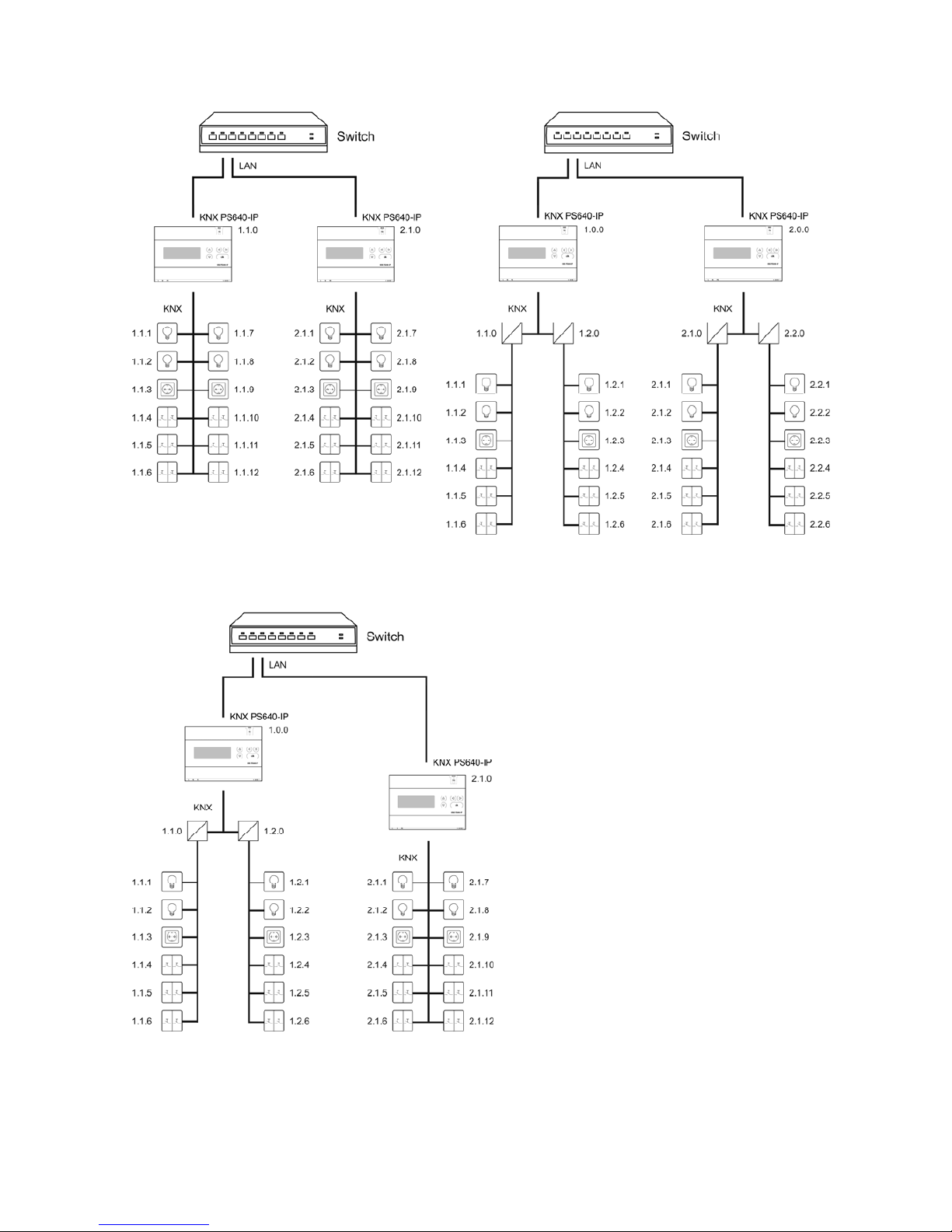
Coupler function (KNXnet/IP Routing)
The Power Supply System KNX PS640+IP can operate as a line and/or backbone
coupler. In both cases, the LAN (IP) acts as a backbone.
5
KNX PS640+IP as a line coupler KNX PS640+IP as a backbone coupler
KNX PS640+IP as a backbone and line coupler
The physical address assigned to the
KNX PS640+IP determines whether the
device operates as a line or backbone coupler. If the physical address is in the form of
x.y.0 (x, y: 1..15), the router operates as a line coupler. If it is in the form of x.0.0 (x:
1..15), the router acts as a backbone coupler.

6
Attention: If the KNX PS640+IP is used as a backbone coupler (x.0.0), there must be no
KNX IP Router in the topology beneath it. For example, if a KNX PS640+IP has the
physical address of 1.0.0, there must be no KNX IP Router with the address 1.1.0.
If the KNX PS640+IP is used as a line coupler (x.y.0), there must be no KNX IP Router in
the topology above it. For example, if a KNX PS640+IP has the physical address of 1.1.0,
there must be no KNX IP Router with the address 1.0.0.
The KNX PS640+IP has a filter table and thus contributes to reducing bus load. The filter
table is automatically generated by the ETS.
Because of the speed difference between the Ethernet (10 Mbit/s) and KNX (9.6 kbit/s), a
far greater number of telegrams can be transmitted on IP. If several consecutive
telegrams are transmitted on the same line, they must be buffered in the router to avoid
telegram loss. The KNX PS640+IP 750 has a memory for 150 telegrams (from IP to
KNX/EIB).
Bus access (KNXnet/IP Tunnelling)
The Power Supply System KNX PS640+IP can be used as an interface to KNX. KNX can
be accessed from any point in the LAN. For this purpose, a second physical address
must be assigned in the ETS. Please refer to chapter “ETS Connection Manager”.
Power Supply
Housing example with central operating unit
7
Installation and commissioning
Installation, testing, operational start-up and troubleshooting should only be
performed by an electrician.
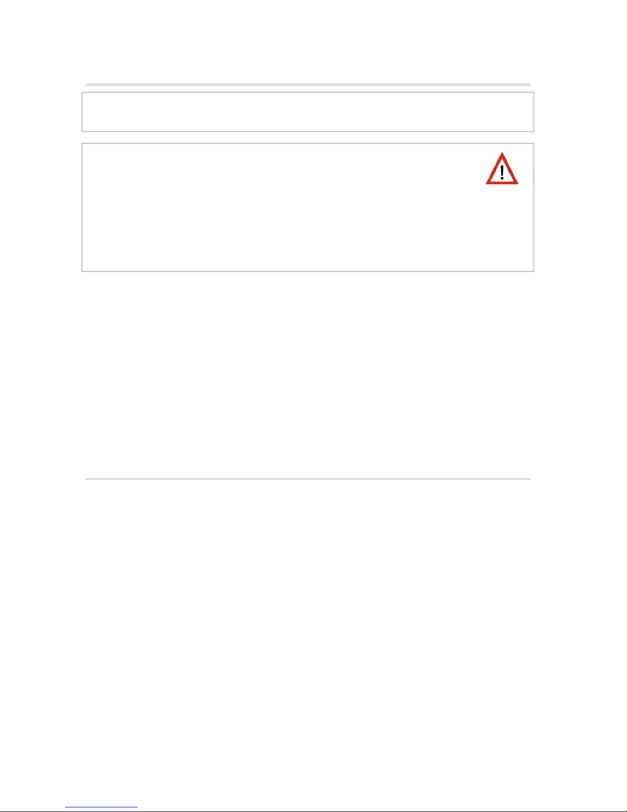
DANGER! Risk to life from live voltage (mains voltage)!
There are unprotected live components inside the device.
• VDE and national regulations are to be followed.
• Ensure that all lines to be assembled are free of voltage and take
precautions against accidental switching on.
• Do not use the device if it is damaged.
• Take the device or system out of service and secure it against unintentional
use, if it can be assumed, that risk-free operation is no longer guaranteed.
The device is only to be used for its intended purpose. Any improper modification or
failure to follow the operating instructions voids any and all warranty and guarantee
claims.
After unpacking the device, check it immediately for possible mechanical damage. If it
has been damaged in transport, inform the supplier immediately.
The device may only be used as a fixed-site installation; that means only when
assembled and after conclusion of all installation and operational start-up tasks and
only in the surroundings designated for it.
Elsner Elektronik is not liable for any changes in norms and standards which may occur
after publication of these operating instructions.
Connection
Observe the correct installation. Incorrect installation may destroy the power supply
system or connected electronic devices.
After the auxiliary voltage is applied the device will enter an initialization phase lasting
about 5 seconds. During this phase no information can be received via the bus.

8
Housing
1 LAN connection (RJ45, for
Ethernet patch cable)
2 Programming LED and
programming button
3 Bus connection (KNX terminal
+ / -)
4 Input operating voltage 230 V
AC, L / N / PE
5 Output direct current voltage 24
V DC, + / -
Connections 4 and 5 are suitable for
solid conductors up to 1.5 mm² or
conductors with fine wires.
Scheme
KNX communication of IP interface and
power supply unit
The device has got two KNX interfaces, one for the “PLUS” functions of the power
supply unit and one for the IP router. The functions are registered at the bus separately
and parametrised in different product files (ETS).
Auxiliary Voltage 24 V DC
(max. 150 mA)
9
Addressing
IP interface and KNX power supply unit are addressed separately at the bus.
Addressing the IP interface
The IP interface is supplied with the bus address 15.15.0. You can program another
address in the ETS (product file of IP interface) by overwriting the 15.15.0 address or by
teaching via the programming key at the unit.
Addressing the KNX power supply unit
The power supply unit is supplied with the bus address 15.15.250. You can program
another address in the ETS (product file of power supply unit) by overwriting the
15.15.250 address or by using the “Prog. Mode” of the unit (see chapter Addressing the
power supply unit (programming mode)).
Settings in der ETS
Different product files are used for setting of the IP interface and the KNX functions of
the power supply unit.
Parametrise the IP interface
Use the product file of PS640-IP power supply unit, item number 70142.
For description of parameters please see manual, chapter Setting the IP interface in the
ETS.
Parametrise the KNX power supply unit
Use the product file of PS640+(USB) power supply unit, item numbers 70141, 70144.
For description of parameters please see manual, chapter Setting the bus functions of
the power supply unit in the ETS.
Settings at the device
Starting position
The following may be read off and set on the display of the Power Supply System KNX
PS640+IP:
Reset of a line
Recall of the data memory with operating hours, overcharge, external electrical
surge, internal electrical surge, short circuit and excess temperature
Recall of the operating data bus voltage, bus current and temperature
el
sner e
l
e
kt
ron
ik
KNX PS640+IP
Normal Operation
Diagnostics >

10
Language of display
Activate the programming mode for addressing of the power supply unit at the
KNX bus
The display will be dimmed after 60 seconds if no key has been pressed during this
time. In addition, the backlight of the display will be switched off automatically if the
temperature inside the housing exceeds 50°C. Thus a high thermal load is avoided.
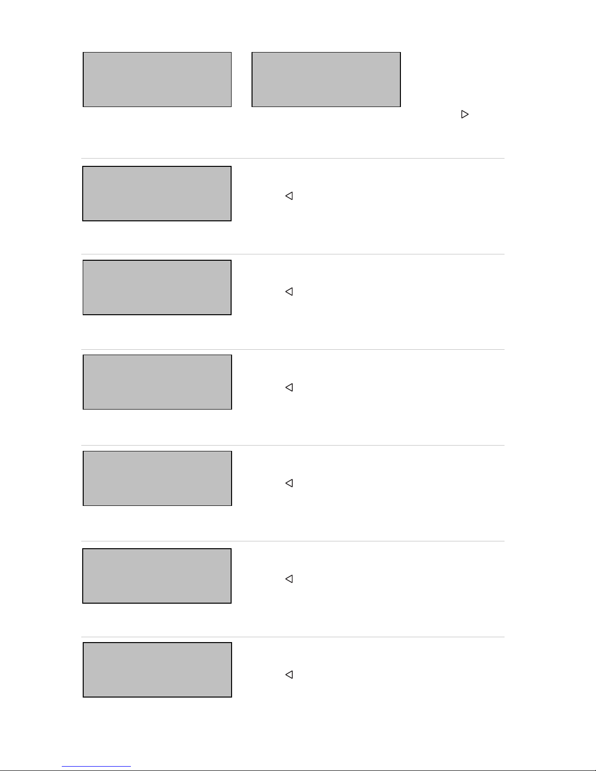
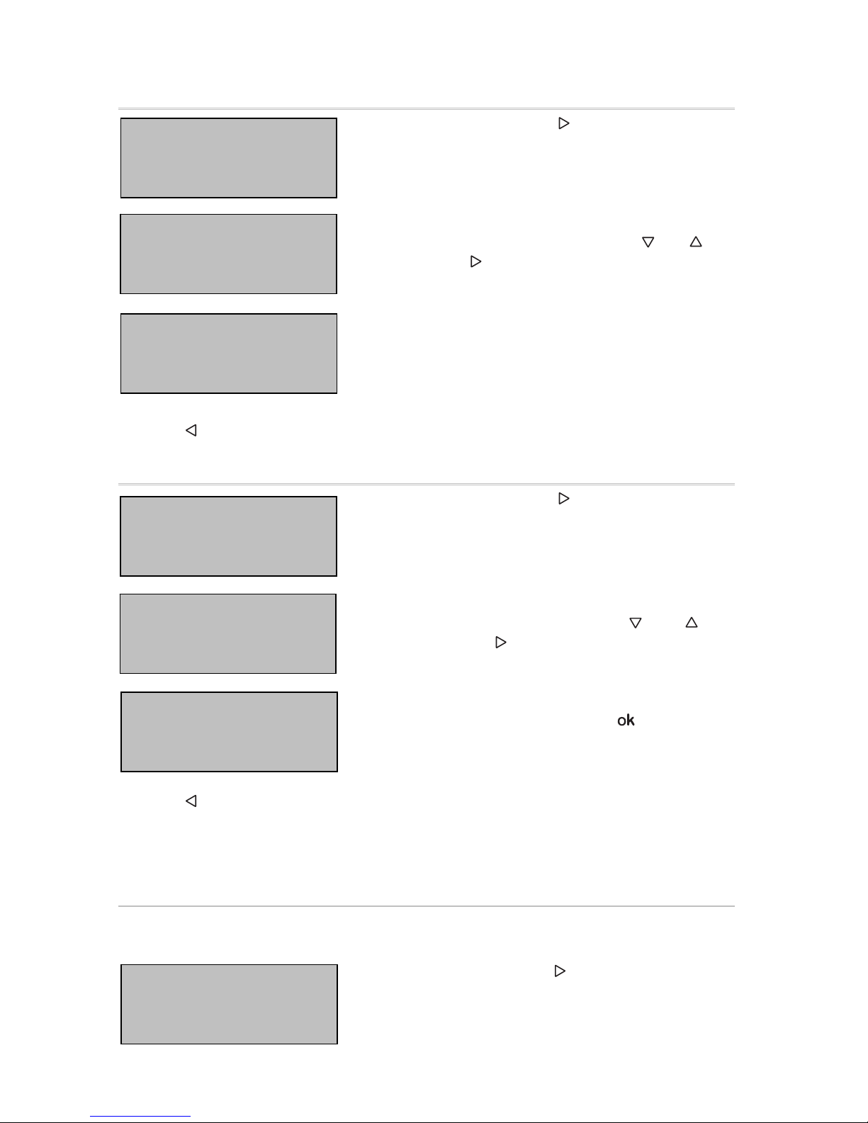
Line reset
In starting position, press key once to get into the
sector “Diagnostics”.
Press key once more in order to get into the sector
“Line reset”.
Move the cursor (flashing rectangle at right edge) to
the desired setting with the keys or and confirm
with key .
Yes: Reset is activated. The line is switched to neutral and shorted. The
basic setting displays: “Reset is active!”
No: Reset not activated. The power supply system works in normal
operation.
30 seconds: A reset of 30 seconds is started. Afterwards, the line is supplied
with voltage as usual. During the reset state, which lasts 30
seconds, the basic setting displays: “Reset active: XX sec”
(countdown).
With key , you return to the previous menu level.
Data memory
In starting position, press key once.
Move the cursor (flashing rectangle at right edge) to
the “Data memory” menu with the keys and and
confirm with key .
el
sn
e
r e
l
e
kt
ron
ik
KNX PS640+IP
Normal Operation
Diagnostics >
Li
ne
R
e
se
t
>
™
Data Memory >
Operating Data >
Language
R
ese
t
:
Y
es
™
No
30 seconds
Reset not active!
el
sner e
l
e
kt
ron
ik
KNX PS640-IP
Normal Operation
Diagnostics >
Li
ne
R
e
se
t
>
Data Memory > ™
Operating Data >
Language > v
11
Move the cursor to the desired menu with the up and down keys and press key .
Operating hours
The operating hours of the power supply system are
displayed in years, days and hours.
With key you return to the previous menu level.
Overload
The number of overload incidents and the total time in
days, hours and minutes are displayed.
With key you return to the previous menu level.
External overvoltage
The number of external overvoltage incidents is
displayed.
With key you return to the previous menu level.
Internal overvoltage
The number of internal overvoltage incidents is
displayed.
With key you return to the previous menu level.
Short circuit
The number of short circuit incidents at the bus is
displayed.
With key you return to the previous menu level.
Excess temperature
The number of excess temperature incidents on the
circuit board of the device is displayed.
With key you return to the previous menu level.
Sh
or
t
c
i
rcu
it
>
Excess Temperat. >
Hours of Operation> ™
Overload >
Ext. Overvoltage >
Int. Overvoltage > v
R
un
ti
me:
0
year
s
0 day 0 hrs.
< = Back
O
ver
l
oa
d
d
e
t
ec
t
e
d
0 times. Duration:
0 day. 0 hrs. 0 min
< = Back
E
x
t
erna
l
O
vervo
lt
age
was detected
0 times.
< = Back
I
n
t
erna
l
O
vervo
lt
age
was detected
0 times.
< = Back
A
s
h
or
t
at
th
e
b
us
was detected
0 times.
< = Back
E
xcess
T
empera
t
ure
on the board
was detected
0 times!
12
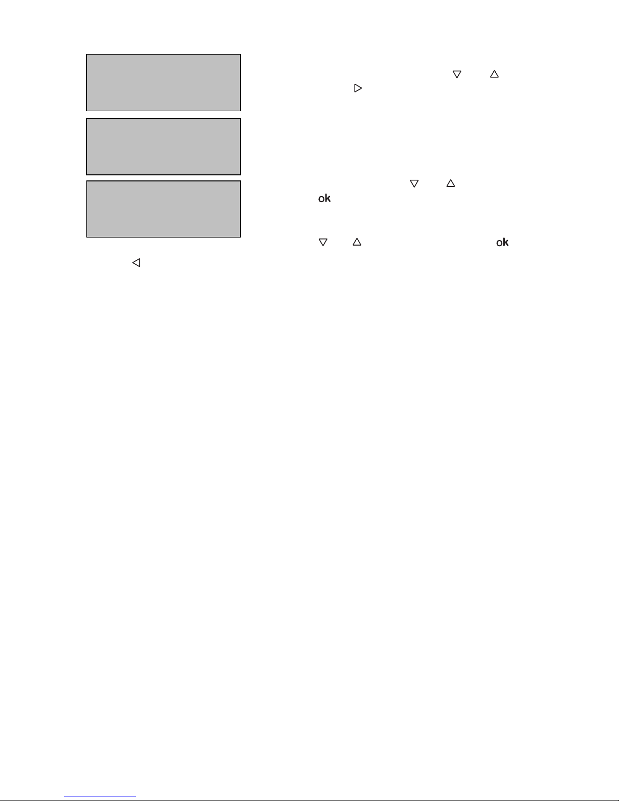
Operating data
In starting position, press key once.
Move the cursor (flashing rectangle at right edge) to
the “Operating Data” menu with the keys and and
confirm with key .
The current values of
Bus voltage
Bus current
Temperature on the circuit board of the device
are displayed.
With key you return to the previous menu level.
Language
In starting position, press key once.
Move the cursor (flashing rectangle at right edge) to
the “Language” menu with the keys and and
confirm with the key .
Move the cursor to the desired language with the up
and down keys and press the key . The display
automatically jumps to the previous menu in the
desired language.
With key you get back by one menu level to the basic setting.
Addressing the power supply unit (programming
mode)
To set the physical address of the power supply unit at the KNX bus, the programming
mode is activated here.
Instarting position, press key once.
el
sner e
l
e
kt
ron
ik
KNX PS640+IP
Normal Operation
Diagnostics >
Li
ne
R
e
se
t
>
Data Memory >
Operating Data > ™
Language > v
el
sner e
l
e
kt
ron
i
k
KNX PS640-IP
Normal Operation
Diagnostics >
L
i
ne
R
e
se
t
>
Data Memory >
Operating Data >
Language > ™
S
prac
h
e :
D
eu
t
sc
h
™
Language :English
Idioma :Espanol
Taal :Hollands
el
sner e
l
e
kt
ron
ik
KNX PS640+IP
Normal Operation
Diagnostics >
B
us
V
olt
age
29
.
4
V
Bus Current 320 mA
Temperature 42.1°C
13
Move the cursor (flashing rectangle at right edge) to
the “Prog. Mode” menu with the keys and and
confirm with the key .
Move the cursor with the keys and to “On” and
press the key . The programming mode is active just
as long the text “Prog. Mode active” is shown.
To switch off programming mode, move the cursor
with the keys and to “Off” and press the key .
With key you get back by one menu level to the basic setting.
L
i
n
e
R
e
se
t
>
Data Memory >
Operating Data >
Language > v
P
rog.
M
o
d
e
>
™
P
rog.
M
o
d
e
:
O
n
™
Off
PLUS Funktions are
active in Prog.Mode

14
Setting of parameters in the ETS
Parameters of the IP interface
General
Device name [free entry]
The KNX PS640+IP can be assigned a name of your choice. The device name should be
descriptive (e. g. Line TF). It is used to search for and recognize a device.
Monitoring bus voltage failure disable • enable
If a KNX failure is detected, it is reported on the IP. Return of the bus voltage is also
reported.
IP address assignment automatic (DHCP) • manual
Automatic (DHCP): The IP address is automatically assigned on the DHCP, i.e.
additional settings are not required. To be able to use this function, there must be a
DHCP server in the LAN (many DSL routers have an integrated DHCP server).
Manual: In this case, the IP address, the subnet and the gateway IP address must be
entered manually.
15
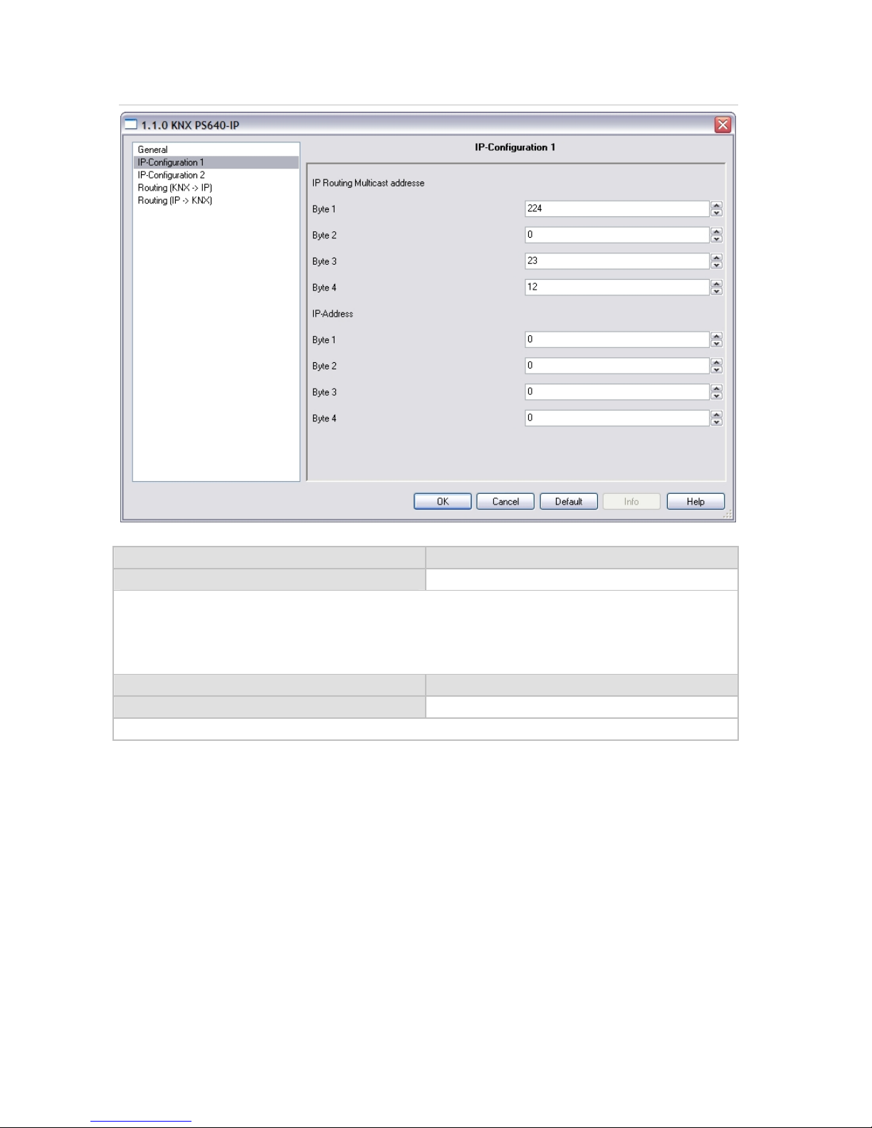
IP configuration
IP Routing Multicast address
Byte 1 / 2 / 3 / 4 0 … 255
This address is used for routing telegrams on IP. The multicast IP address 224.0.23.12
was reserved (KNXnet/IP) at the IANA (Internet Assigned Numbers Authority) for this
purpose. If a different multicast IP address is required, it must lie within the range of
239.0.0.0 to 239.255.255.255.
IP address
Byte 1 / 2 / 3 / 4 0 … 255
This is the IP address of the KNX PS640+IP.

16
IP subnet
Byte 1 / 2 / 3 / 4 0 … 255
Enter the subnet mask here. The device uses the values entered in this mask to
determine whether there is a communications partner in the local network. If there is
no partner in the local network, the device will not send the telegrams directly to the
partner but to the gateway that routes the telegram.
IP gateway address
Byte 1 / 2 / 3 / 4 0 … 255
Enter the IP address of the gateway here.
Note: If the KNX PS640+IP will only be used in the local LAN, the entry of 0.0.0.0 can
remain unchanged.
Example of assigning IP addresses
A PC is to be used to access the KNX PS640-IP.
IP address of the PC: 192.168.1.30
Subnet of the PC: 255.255.255.0
The KNX PS640-IP is located in the same local LAN, i. e. it uses the same subnet. The
subnet constrains the IP addresses that can be assigned. In this example, the IP address
of the KNX PS640-IP must be 192.168.1.xx, where xx can be a number from 1 to 254
(with the exception of 30, which is already in use). It must be ensured that no numbers
are assigned twice.
IP address of the KNX PS640-IP: 192.168.1.31
Subnet of the KNX PS640-IP: 255.255.255.0
17
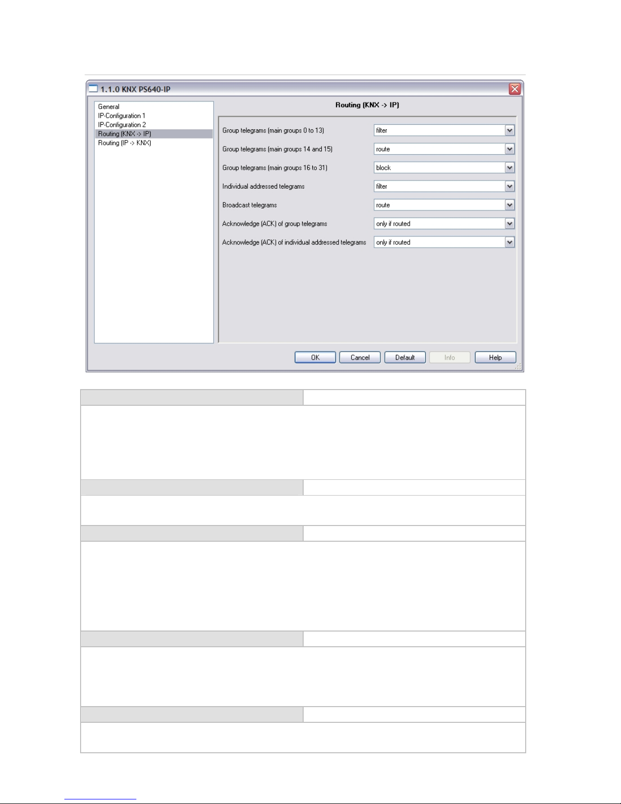
Routing (KNX -> IP)
Group telegrams (main group 0 to 13) block • route • filter
Block: No group telegrams of this main group are routed to IP.
Route: All group telegrams of this main group are routed to IP independent of the filter
table. This setting is for testing purposes only.
Filter: The filter table is used to check whether or not the received group telegram
should be routed to IP.
Group telegrams (main groups 14 and 15) block • route
Block: No group telegrams of main groups 14 and 15 are routed to IP.
Route: All group telegrams of main groups 14 and 15 are routed to IP.
Group telegrams (main groups 16 to 31) block • route
Block: No group telegrams of these main groups are routed to IP.
Route: An additional page appears on which the routing of main groups 16 to 31 can be
disabled or enabled in pairs.
Note: The group addresses of main groups 16 to 31 are reserved addresses that can be
used for special applications (e.g. in Easy Mode). These group addresses are not
available in the ETS.
Physically addressed telegrams block • route • filter
Block: No physically addressed telegrams are routed to IP.
Route: All physically addressed telegrams are routed to IP.
Filter: The physical address is used to check whether the received physically addressed
telegram should be routed to IP.
Broadcast telegrams block • route
Block: No received broadcast telegrams are routed to IP.
Route: All received broadcast telegrams are routed to IP.

18
Acknowledge (ACK) of group telegrams always • only if routed
Always: An acknowledge is generated for every received group telegram (from KNX).
Only if routed: An acknowledge is only generated for received group telegrams (from
KNX) if they are routed to IP.
Acknowledge (ACK) of physically
addressed telegrams
always • only if routed • answer with
NACK
Always: An acknowledge is generated for every received physically addressed telegram
(from KNX).
Only if routed: An acknowledge is only generated for received physically addressed
group telegrams (from KNX) if they are routed to IP.
Answer with
NACK: Every received physically addressed telegram (from KNX) is responded to with
NACK (not acknowledge). This means that communication with physically addressed
telegrams on the corresponding KNX line is not possible. Group communication (group
telegrams) is not affected. This setting can be used to block attempts at manipulation.
Routing (IP -> KNX)
Group telegrams (main groups 0 to 13) block • route • filter
Block: No group telegrams of these main groups are routed to KNX.
Route: All group telegrams of this main group are routed to KNX independent of the
filter table. This setting is used for testing purposes only.
Filter: The filter table is used to check whether the received group telegram should be
routed to KNX.

19
Group telegrams (main groups 14 and 15) block • route
Block: No group telegrams of main groups 14 and 15 are routed to KNX.
Route: All group telegrams of the main groups 14 and 15 are routed to KNX.
Group telegrams (main groups 16 to 31) block • route
Block: No group telegrams of these main groups are routed to KNX.
Route: An additional page appears on which the routing of main groups 16 to 31 can be
disabled or enabled in pairs.
Physically addressed telegrams block • route • filter
Block: No physically addressed telegrams are routed to KNX.
Route: All physically addressed telegrams are routed to KNX.
Filter: The physical address is used to check whether the received physically addressed
telegram should be routed to KNX.
Broadcast telegrams block • route
Block: No received broadcast telegrams are routed to KNX.
Route: All received broadcast telegrams are routed to KNX.
Resending of group telegrams block • route
Disable: The received group telegram is not resent to KNX in case of a fault.
Enable: The received group telegram is resent up to three times in case of a fault.
Resending of physically addressed
telegrams
block • route
Disable: The received physically addressed telegram is not resent to KNX in case of a
fault.
Enable: The received physically addressed telegram is resent up to three times in case
of a fault.
Resending of broadcast telegrams block • route
Disable: The received broadcast telegram is not resent to KNX in case of a fault.
Enable: The received broadcast telegram is resent up to three times in case of a fault.

20
Communication settings in the ETS
If the IP-configuration of the KNX PS640+IP is valid the device can act as an interface to
KNX. The following configuration is necessary:
Select the button “Settings” and the tab “Communication” in the main window of
ETS4. All available connections are listed by “Configured connections”. Select the
desired connection.
The button “Local settings” enables the configuration of the individual address, which
is used for bus access.
A dummy device may be created in the ETS-project to reserve this address.
The KNX PS640+IP supports up to 5 connections simultaneously. An additional physical
address has to be reserved for every connection. The first additional physical address is
allocated (as shown above) to the connection in the ETS. The remaining additional
addresses can be assigned directly by the device, in which cast the learn button should
be pressed for at least one second. The automatic address allocation is performed as:
Connection 2 contains the next higher address from Connection 1,
Connection 3 the next higher from Connection 2
etc.
For example:
Connection 1 uses the additional individual address 15.15.250.
Connection 2 is automatically set to 15.15.251, connection 3 is 15.15.252,
connection 4 is 15.15.253 and connection 5 is 15.15.254.
The assignment of the additional individual addresses is shown by a fast blinking learn
led.
Note: It is necessary to check whether the additional individual addresses are unused
before they are assigned.
For new devices (i.e. in the factory settings state), only the additional individual address
of the first connection is active with the address 15.15.250. To support multiple
concurrent connections the additional address assignment is required.
This manual suits for next models
1
Table of contents
Other Elsner Power Supply manuals


Popular Power Supply manuals by other brands

Vertiv
Vertiv NetSure V200D50 Installation and user manual

Altronix
Altronix VertiLine24C Series installation guide

Rigol
Rigol DP700 Series Calibration guide

Altronix
Altronix ALTV2432UL3 Series installation guide

CARLO GAVAZZI
CARLO GAVAZZI SPDE 75 Series Installation and operation manual

APM
APM SPS Series quick guide


Red Ion
Red Ion PSDR030W manual

ZALMAN
ZALMAN ZM450-GS user manual

VOSS.farming
VOSS.farming Impuls duo DV 40 operating instructions

Cabletron Systems
Cabletron Systems MMAC-3 Addendum

Balluff
Balluff BAE PS-XA-1W-24-150-608-I installation guide

EPS Stromversorgung
EPS Stromversorgung PS 5040-10 A operating guide