Elsner KNX PS640+ Guide

2
Contents
Productdescription ...................................................................................................... 3
Technical data.......................................................................................................................................3
Installation andCommissioning................................................................................... 4
Installation ............................................................................................................................................5
Settingsofthe device.................................................................................................. 6
Starting position...................................................................................................................................6
Line reset...............................................................................................................................................7
Data memory........................................................................................................................................7
Operating data......................................................................................................................................8
Language..............................................................................................................................................9
Transmission protocol.................................................................................................. 9
Abbreviations.......................................................................................................................................9
Listing of all communication objects...............................................................................................10
Setting ofparameters (Software ETS)........................................................................ 11
Generalsettings.................................................................................................................................11
Messages............................................................................................................................................12
Current thresholdvalue.....................................................................................................................14
KNX PS640+und KNX PS640+USBfromsoftwareversion 1.01, ETSprogrammeversion 1.1
Version:15.05.2013. Errorsexcepted. Subject to technical changes.

3
Product description
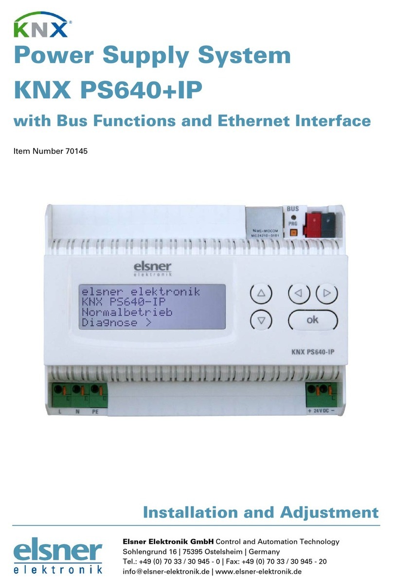
ThePowerSupplySystemsKNXPS640+and KNXPS640+USB delivera29Vbus
voltagefortheKNXsystem and 24 VDC supplyvoltagefor24 Vdevices.Special
operatingconditionssuchas shortcircuit, electricalsurge,overchargeorexcess
temperaturearerecordedand may bereadoff on thedisplay.Thepresentpower
dischargeisdisplayedas well. It ispossibletoresettheconnectedbusdevices directly
bymeansofthekey pad.
Inaddition all functionscanberealisedviathebus,too,e.g.thetransferof malfunction
messages and operatingdataand atime/periodreset. Malfunction messages arestored
bytheKNXPS640+(USB).
Functions:
Deliversa 29V KNXbusvoltage (reduced), outputcurrentmax.640 mA, short-
circuitproof
Delivers 24 VDC (not reduced), outputcurrent max.150 mA
Reset ofalinedirectlyon thedevice
Recordofoperatinghours,overload, externalovervoltage,internalovervoltage,
short circuit andexcesstemperature
Displayofoperating databusvoltage,buscurrent andtemperatureofthedevice
Thedisplay may beshowninGerman,English, SpanishorDutch
Busconnection fordatatransfer(e.g.malfunctionmessages,operatingdata)
Possibilityforreset anddiagnosticsviathebus
OnlyKNXPS640+USB:USB interface forbusaccess viaPC
The programmefile forKNXsoftwareETS (formatVD2)isreadyfordownloadon the
ElsnerElektronikwebsiteat www.elsner-elektronik.de inthe“Service” menu.
Technical data
Housing
Plasticmaterial
Colour
White
Mounting
Snap
-
on fittingon mounting rails
Protection category
IP20
Dimensions
appr
ox. 123x89 x61 (WxHxD,mm),7widthunits
Weight
approx. 370g
Ambienttemperature
Operation
-
5…+45 °C,
s
torage
-
25…+70°C
Ambientairhumidity
max.95%R
H, avoidbedewing
Operatingvoltage
230 VAC , 50Hz
PowerconsumptionStandby
approx.
2.
3
W
Outputs
•
KNXbusvoltage29V(reduced),
Output currentmax.640 mA, short-circuitproof
•24VDC (notreduced),Output currentmax.150 mA
•KNXdata
Dataoutput
KNX+/
-
busterminal plug

4
BCU type
Ownmicrocontroller
PEI type
0
Group address
es
max.200
Allocations
max.200
Communicationobjects
27
Thefollowingstandardshave beenconsideredfortheevaluationoftheproductin
termsofelectromagneticcompatibility:
Transient emissions:
EN 60730-1:2000SectionEMV(23,26,H23,H26) (thresholdcategory: B)
EN 50090-2-2:1996-11+A1:2002-01(thresholdcategory: B)
EN 61000-6-3:2001 (thresholdcategory: B)
Interferenceresistance:
EN 60730-1:2000SectionEMV(23,26,H23,H26)
EN 50090-2-2:1996-11+A1:2002-01
EN 61000-6-1:2004
Theproducthas beentestedfortheabove mentionedstandardsbyanaccreditedEMV
laboratory.
Installationand Commissioning
Attention!Mainsvoltage!The legal national regulations
must be compliedwith.
Installation,inspection,commissioning andtroubleshooting ofthepowersupply
system mustonlybecarriedoutbyacompetentelectrician.Disconnectall lines tobe
assembled, andtake safetyprecautionsagainst accidentalswitch-on.
Thepowersupplyisexclusivelyintendedforappropriateuse.Witheachinappropriate
changeornon-observance oftheinstructionsforuse,anywarrantyorguaranteeclaim
willbevoid.
Afterunpacking thedevice,check immediatelyforanymechanicaldamages.Incase of
transport damage,thismustimmediatelynotifiedtothesupplier.
Ifdamaged, thepowersupplysystemmust notbeput
intooperation.
If anoperationwithoutriskmay supposedlynotbeguaranteed,theplantmustbeput
out ofoperationand besecuredagainst accidentaloperation.
Thepowersupplysystem mustonlybeoperatedas stationarysystem,i.e.onlyina
fittedstateand aftercompletion ofallinstallation and start-up works,and onlyinthe
environmentintendedforthispurpose.
ElsnerElektronikdoesnotassume anyliabilityforchanges instandardsafter
publicationofthisinstructionmanual.

5
Installation
Observethecorrectinstallation.Incorrectinstallation maydestroythepowersupply
systemorconnectedelectronicdevices.
Aftertheauxiliaryvoltageisappliedthedevicewillenteraninitialisation phase lasting5
seconds.Duringthisphase no information canbereceivedviathebus.
Housing
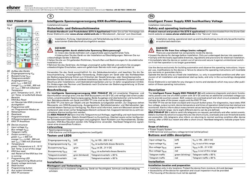
1Busvoltagepower
OUT(KNX terminal+/-)
2ProgrammingLEDand
programmingbushbutton
3Busdata(KNXterminal
+ /-),connectionforline
ormainlineorsector
4Input operating voltage
230 VAC, L/N/PE
5USB interface
(onlyKNXPS640+USB)
6Output direct current
voltage24 VDC,+/-
Connections4and6are
suitableforsolidconductors
up to1.5mm² orconductors
withfinewires.
Scheme
Auxiliary supply 24 VDC
(max. 150mA)

6
Connection examplefor aKNX system without linecoupler
Connection examplefor aKNX system with linecoupler
Settingsofthedevice
Starting position
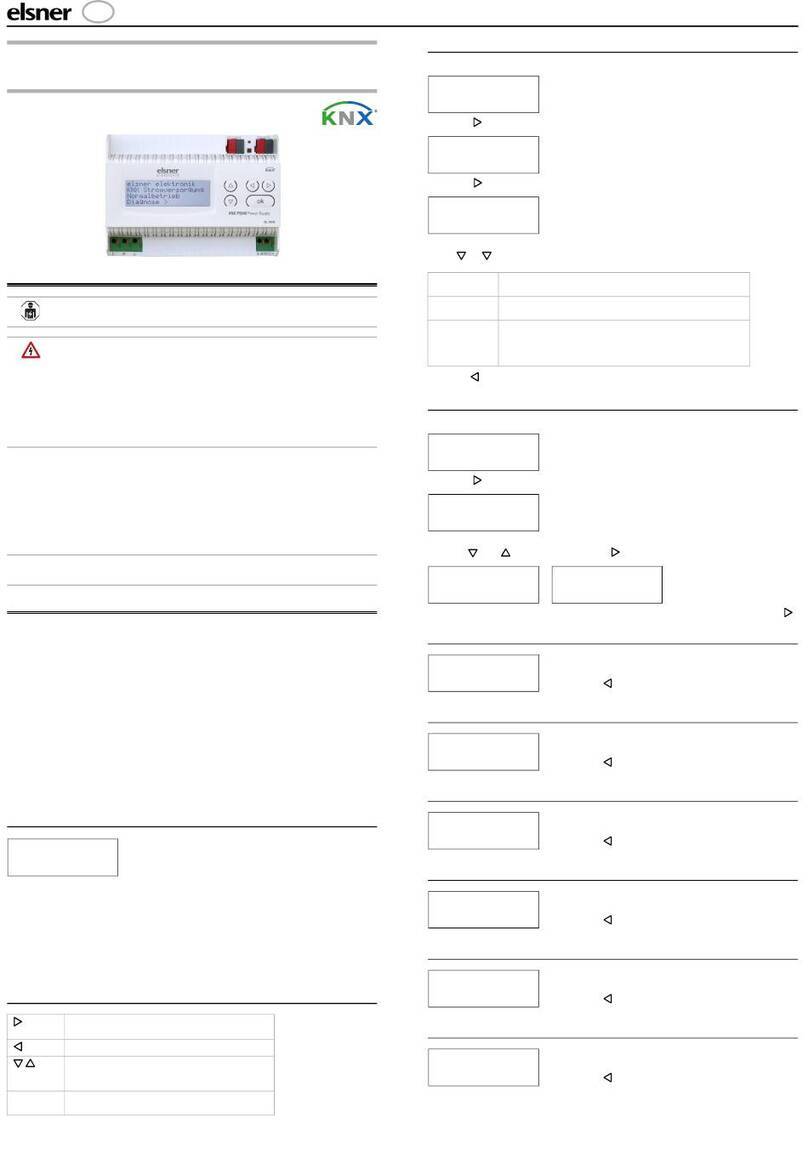
Thefollowingmaybereadoffandseton thedisplayofthePowerSupplySystemKNX
PS640+:
Reset of aline
Recallofthedatamemorywithoperatinghours,overcharge,external electrical
surge,internalelectrical surge,short circuitandexcesstemperature
Recalloftheoperating databusvoltage,buscurrentand temperature
Languageofdisplay
elsnerelektronik
KNXPowerSupply
NormalOperation
Diagnostics>

7
Thedisplay isdimmedafter60 secondsifduring thisperiodno keyispressed.
Linereset
Instartingposition, press key once.
Press key once moreinordertogetintothesector
“Linereset”.
Move thecursor(flashing rectangleatrightedge)to
thedesiredsetting withthekeys or and confirm
withkey .
Yes:Resetisactivated.Thelineisswitchedtoneutraland shorted.The
basicsettingdisplays: “Resetisactive!”
No:Resetnotactivated.Thepowersupplysystem worksinnormal
operation.
30 seconds:Aresetof30 secondsisstarted.Afterwards,thelineissupplied
withvoltageas usual. Duringtheresetstate,whichlasts30
seconds,thebasicsetting displays:“Resetactive:XX sec”
(countdown).
Withkey , you returntothepreviousmenu level.
Datamemory
Instartingposition, press key once.
Move thecursor(flashing rectangleatrightedge)to
the“Datamemory”menu withthekeys and and
confirmwithkey .
Move thecursortothedesiredmenuwiththeup and downkeysandpress key .
Shortcircuit>
ExcessTemperat.>
HoursofOperation>™
Overload>
Ext.Overvoltage>
Int.Overvoltage>
LineReset>
DataMemory >™
OperatingData>
Language>
elsnerelektronik
KNXPowerSupply
NormalOperation
Diagnostics>
LineReset>™
DataMemory >
OperatingData>
Language
Reset:Yes™
No
30seconds
Resetnotactive!
elsnerelektronik
KNXPowerSupply
NormalOperation
Diagnostics>

8
Operating Hours
heoperating hoursofthepowersupplysystem are
displayedinyears, daysand hours.
Withkey you returntothepreviousmenulevel.
Overload
Thenumberofoverloadincidentsand thetotaltime in
days, hoursandminutes aredisplayed.
Withkey you returntothepreviousmenulevel.
External Overvoltage
Thenumberofexternalovervoltageincidentsis
displayed.
Withkey you returntothepreviousmenulevel.
Internal Overvoltage
Thenumberofinternalovervoltageincidentsis
displayed.
Withkey you returntothepreviousmenulevel.
Short Circuit
Thenumberofshortcircuitincidentsatthebusis
displayed.
Withkey you returntothepreviousmenulevel.
Excess Temperature
Thenumberofexcesstemperatureincidentson the
circuitboardofthedevice isdisplayed.
Withkey you returntothepreviousmenulevel.
Operating data
Instartingposition, press key once.
Runtime:0years
0day0hrs.
<=Back
Over
loaddetected
0times. Duration:
0day. 0hrs.0min
<=Back
ExternalOvervoltage
wasdetected
0times.
<=Back
InternalOvervoltage
wasdetected
0times.
<=Back
Ashortatthebus
wasdetected
0times.
<=Back
ExcessTemperature
ontheboard
wasdetected
0times!
elsnerelektronik
KNXPowerSupply
NormalOperation
Diagnostics>

9
Move thecursor(flashing rectangleatrightedge)to
the“Operating Data” menu withthekeys and and
confirmwithkey .
Thecurrent valuesof
Busvoltage
Buscurrent
Temperatureonthecircuitboardofthedevice
aredisplayed.
Withkey you returntothepreviousmenulevel.
Language
Instartingposition, press key once.
Move thecursor(flashing rectangleatright edge) to
the“Language”menuwiththekeys and and
confirmwiththekey .
Move thecursortothedesiredlanguagewiththeup
and downkeys and press thekey .Thedisplay
automaticallyjumpstothepreviousmenuinthe
desiredlanguage.
Withkey you getback byonemenu leveltothebasicsetting.
Transmission protocol
Abbreviations
Flags:
CCommunication
RRead
WWrite
TTransmit
UUpdate
BusVoltage29.4V
BusCurrent320 mA
Temperature42.1°C
LineReset>
DataMemory >
OperatingData>™
Language>
LineReset>
DataMemory >
OperatingData>
Language>™
Sprache :Deutsch™
Language:English
Idioma:Espanol
Taal:Hollands
elsnerelektronik
KNXPowerSupply
NormalOperation
Diagnostics>

10
Listing ofallcommunicationobjects
No.
Name
Function
EIStype
Flags
0Busvoltage [V]Output14.030CRT
1Buscurrent [mA]Output9.021 CRT
2Permanent reset(1 =active |0 =inactive)Input 1.003 CRW
3Timereset
(1 =30 secondsactive |0 =inactive)
Input 1.003 CRW
4Resetstatus of the line
(1 =active |0 =inactive)
Output1.002 CRT
5Overload(0 =normal |1 =overload) Output1.002 CRT
6external overvoltage
(0 =normal |1 =overvoltage)
Output1.002 CRT
7internal overvoltage
(0 =normal |1 =overvoltage)
Output1.002 CRT
8Shortcircuit
(0 =normal |1 =shortcircuit)
Output1.002 CRT
9Overtemperature
(0 =normal |1 =overtemperature)
Output1.002 CRT
10Systemdefect
(0 =normal |1 =defect)
Output1.002 CRT
111 bitmalfunction collection
(operation =0 |fault=1)
Output1.002 CRT
128 bitstatus collectionOutput5.010 CRT
13DateInput 11.001CRW
14TimeInput 10.001CRW
15Recall errorinformation
(1 =No.+1 |0=No.-1)
Input 1.008 CRW
16Message part1Output16.000CRT
17Message part2Output16.000CRT
18Message part3Output16.000CRT
19Message part4Output16.000CRT
20Thresholdvalue: 16 bitvalue [mA]Input / Output9.021 CRW TU
21Thresholdvalue:
1 =Increment |0 =Decrement
Input 1.008 CRW
22Thresholdvalue: Increment Input 1.017 CRW
23Thresholdvalue: Decrement Input 1.017 CRW
24Thresholdvalue: Switching outputOutput1.002 CRT
25Thresholdvalue: Switching output blockInput 1.003 CRW
26Software version readable 217.001CR

11
Settingofparameters(Software ETS)
General settings
Measured values:
……………………………
Transmission behaviourobject “busvoltage” do not send
• send cyclically
• send incase of change
• send incase of change and cyclically
Sending cycle
(only ifsending “cyclically”)
5 sec 10sec 30sec 1 min … 2h
Change in%
(only ifsending “incaseof change”)
1 … 50
Transmission behaviourobject “buscurrent” do not send
• send cyclically
• send incase of change
• send incase of change and cyclically
Sending cycle
(only ifsending “cyclically”)
5 sec 10sec 30sec 1 min … 2h
Change in%
(only ifsending “incaseof change”)
1 … 100

12
Resetofthe linie:
……………………………
Whatshall be usedforthe reset?
display and keyboard Yes
object “permanent reset”
1 =reset|0 =no reset
No Yes
object “timereset”
1 =30 secondsreset|0 =no reset
No Yes
Use object “resetstatus of the line” No Yes
Other:
……………………………
Maximumtelegramquota 1 2 3 5 10 20 Telegramspersecond
Generalsending delay after
powerup and programming
5 sec 10sec 30sec 1 min … 2h
Messages
1bitmalfunction objects:
……………………………
Object “overload” do not send
• send incase of change
• send incase of change to1
• send incase of change to0
• send incase of change and cyclically
• send incase of change to1 and cyclically
• send incase of change to0 and cyclically

13
Sending cycle
(only ifsending “cyclically”)
5 sec 10sec 30sec 1 min … 2h
Object “external overvoltage” [The setting optionsare similarto object
“overload”]
Object “internal overvoltage” [The setting optionsare similarto object
“overload”]
Object “shortcircuit” [The setting optionsare similarto object
“overload”]
Object “overtemperature” [The setting optionsare similarto object
“overload”]
Object “systemdefect” [The setting optionsare similarto object
“overload”]
1bitmalfunction collection:
……………………………
Object “1 bitmalfunction collection”
Thisobject results ina
disjunction of the 1 bitmalfunction objects
do not send
• send incase of change
• send incase of change to1
• send incase of change to0
• send incase of change and cyclically
• send incase of change to1 and cyclically
• send incase of change to0 and cyclically
Sending cycle
(only ifsending “cyclically”)
5 sec 10sec 30sec 1 min … 2h
8bitstatuscollection:
……………………………
Object “8 bitstatus collection” do not send
• send incase of change
• send incase of change and cyclically
Sending cycle
(only ifsending “cyclically”)
5 sec 10sec 30sec 1 min … 2h
Bit0 =resetstatus of the linie
Bit1 =overload
=value 1
=value 2
Bit2 =external overvoltage
Bit3 =internal overvoltage
=value 4
=value 8
Bit4 =shortcircuit
Bit5 =overtemperature
=value 16
=value 32
Bit6 =current thresholdvalue exceeded
Bit7 =systemdefect
=value 64
=value 128
Acombination oferrormessages ispossible.If e.g.value34 istransferred,thenBit1=
OverloadandBit5=Overtemperatureareset.
Thevaluesetinthemenu “currentthresholdvalue” (see nextchapter) isusedas
currentthresholdvalue.Theadditionalsettingsforhysteresisetc.are not takeninto
accountforthestatuscollection.Bit6“currentthresholdstatusexceeded”isset,ifthe

14
thresholdvaluehas beenexceededfor1minute. Thebit isimmediatelydeletedagain, if
thethresholdvalueisunderrun.
Errorlog:
……………………………
Use errorlogNo Yes
Ifthe errorlog isused:
Object “message part1”sendssignal:
Errorno. (1 =latest error)
Object “message part2”sendssignal:
Errortype
Object “message part3”sendssignal:
Date of errorstart
Object “message part4”sendssignal:
Time of errorstart
Currentthresholdvalue
Use thresholdvalueNo Yes
Ifthe thresholdvalueisused:
Thresholdvalue:
……………………………
Ifthe thresholdvalueissetbyparameter:
Thresholdvalueissetby
Parameter

15
ThresholdvalueinmA 0 … 640
Hysteresisof the thresholdvaluein% 0 … 50
Ifthe thresholdvalueissetbycommunication object:
Thresholdvalueissetby
Communicationobject
The valuecommunicatedlast shall be
maintained
not
• afterrestoration of voltage
• afterrestoration of voltage and
programming (Donot use forfirst
commissioning)
StartthresholdvalueinmA
validuntil 1. communication
(only ifthe value communicatedlast is“not”
maintainedor“afterrestoration of voltage”)
0 … 640
Type of thresholdchange Absolute valuewith a16bitcom.object
Increment/decrement with one comm. object
Increment/decrement with twocomm.
objects
Stepsize inmA
(only with “increment/decrement”)
1 2 5 10 20 50 100
Hysteresisof the thresholdvaluein% 0 … 50
Switchingoutput:
……………………………
Output isat
(TV=Thresholdvalue)
TVabove =1 |TV–hyst. below =0
• TVabove =0 |TV–hyst. below =1
• TVbelow=1 |TV+hyst. above =0
• TVbelow=0 |TV+hyst. above =1
Switching delay from0 to1 none • 1 s 2 s 5 s 10 s … 2 h
Switching delay from1 to0 none • 1 s 2 s 5 s 10 s … 2 h
Switching output sends • send incase of change
• send incase of change to1
• send incase of change to0
• send incase of change and cyclically
• send incase of change to1 and cyclically
• send incase of change to0 and cyclically
Send switching output ina cycle of
(only ifsending “cyclically”)
5 sec 10sec 30sec 1 min … 2h
Blocking:
……………………………
Use block of the switchingoutput No Yes
Ifthe block oftheswitching outputisused:
Use block of the switchingoutput
Yes

16
Evaluation of the blocking object ifvalue 1: block |ifvalue0: release
• ifvalue 0: block |ifvalue1: release
Valueof the blocking object
before 1.communication
0 • 1
Bahaviourof switching output
with blocking do not send telegram
• send 0
• send 1
Thebehaviourwithrelease oftheswitchingoutput dependsonthevalueofthe
parameter“Switchingoutputsends…” (see ”Switchingoutput”)
Valueof parameter
“Switching output sends”:
Setting options“Behaviourof the switching
output with release”:
incase of change do not send telegram
• send status of the switching output
incase of change to 1 do not send telegram
• ifswitching output =1 èsend 1
incase of change to 0 do not send telegram
• ifswitching output =0 èsend 0
incase of change and cyclically send status of the switching output
(no selection)
incase of change to 1 andcyclically ifswitching output =1 èsend 1
(no selection)
incase of change to 0 andcyclically ifswitching output =0 èsend 0
(no selection)
This manual suits for next models
1
Table of contents
Other Elsner Power Supply manuals
Popular Power Supply manuals by other brands
Matsusada Precision
Matsusada Precision DOPF Series instruction manual
Nemtek
Nemtek AGRI 80 instruction manual
Cooper Wheelock
Cooper Wheelock POWERPATH PS-24-8MC installation instructions

Altronix
Altronix VertiLine48MV Series installation guide
CGS Instruments
CGS Instruments QPS400-3 instruction manual
Bucher
Bucher JMX-15P11-R1A0 user manual


