Elsner KNX PS640 User manual
Power Supply System KNX PS640 1
Power Supply System KNX PS640 • Version: 28.11.2023 • Technical changes and errors excepted. • Elsner Elektronik GmbH • Sohlengrund 16 • 75395 Ostelsheim • Germany • www.elsner-elektronik.de • Technical Service: +49 (0) 7033 / 30945-250
EN
KNX PS640 Power Supply System
Manual
Item number 70140
1. Installation and Commissioning
Installation, testing, operational start-up and troubleshooting should
only be performed by an authorised electrician.
DANGER!
Risk to life from live voltage (mains voltage)!
• Inspect the device for damage before installation. Only put undamaged
devices into operation.
• Comply with the locally applicable directives, regulations and provisions for
electrical installation.
• Immediately take the device or system out of service and secure it against
unintentional switch-on if risk-free operation is no longer guaranteed.
Use the device exclusively for building automation and observe the operating inst-
ructions. Improper use, modifications to the device or failure to observe the opera-
ting instructions will invalidate any warranty or guarantee claims.
Operate the device only as a fixed-site installation, i.e. only in assembled condition
and after conclusion of all installation and operational start-up tasks, and only in the
surroundings designated for it.
Elsner Elektronik is not liable for any changes in norms and standards which may
occur after publication of these operating instructions.
For information on installation, disposal, scope of delivery and
technical data, please refer to the installation instructions.
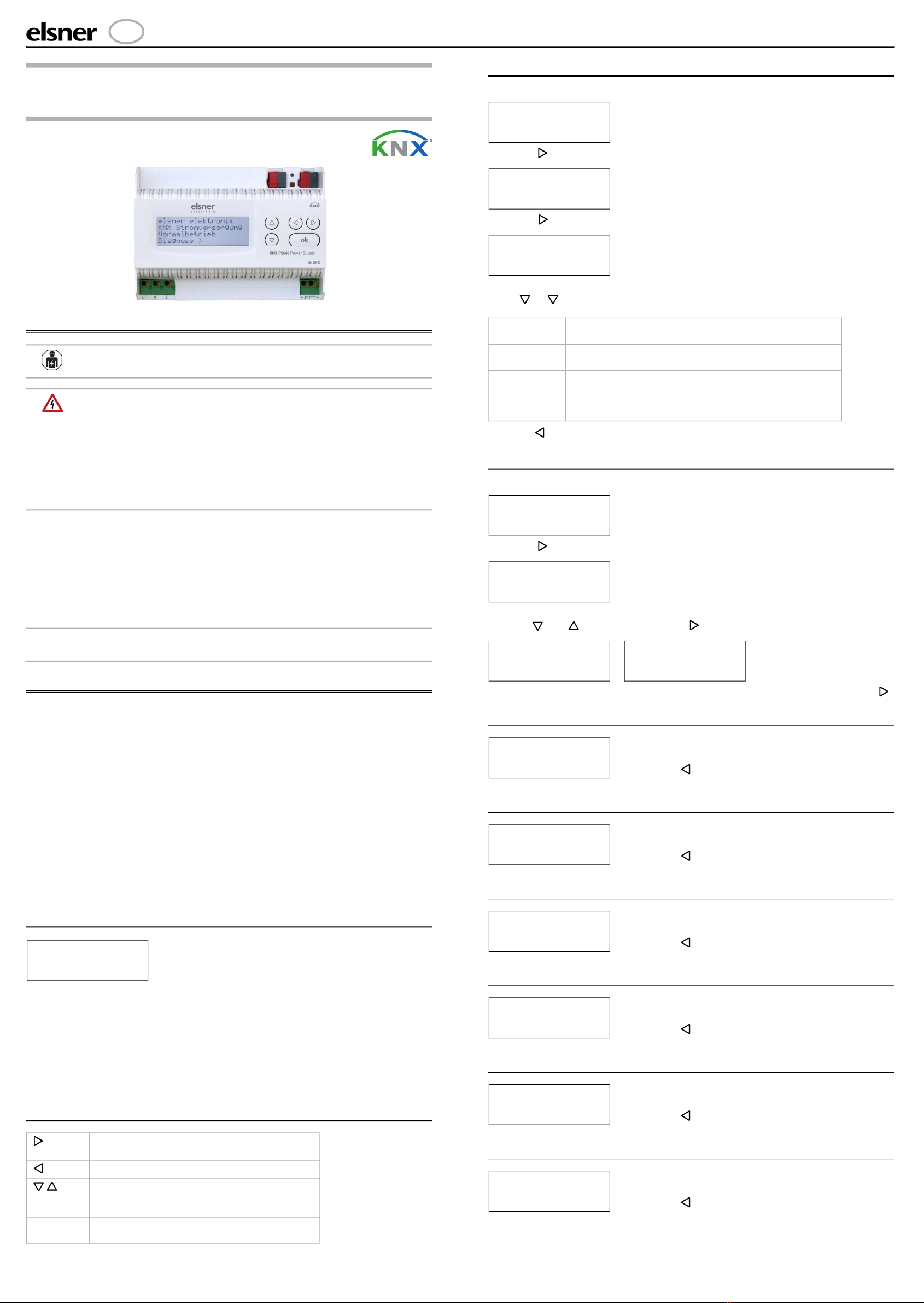
2. Description
The Power Supply System KNX PS640 delivers a 29 V bus voltage for one line
of the KNX building bus system and the supply voltage for 24 V DC devices. Special
operating conditions such as short circuit, overvoltage, overload or excess tempe-
rature are recorded and may be read off on the display. The present power dischar-
ge is displayed as well. A reset of the line is possible via the keypad.
Functions:
• Delivers a 29 V KNX bus voltage (reduced), output current max. 640 mA,
short-circuit proof
• Delivers 24 V DC (not reduced), output current max. 150 mA
•Reset of a line directly on the device
• Record of operating hours, overload, external overvoltage, internal
overvoltage, short circuit and excess temperature
• Display of operating data bus voltage, bus current and temperature of the
device
• The display may be shown in German, English, Spanish or Dutch
2.1. Starting Position
The following may be read off and set on the display of the power supply system
KNX PS640:
• Reset of a line
• Recall of the data memory with operating hours, overcharge, external
electrical surge, internal electrical surge, short circuit and excess temperature
• Recall of the operating data bus voltage, bus current and temperature
• Language of display
The display is dimmed after 60 seconds if during this period no key is pressed.
2.2. Key functions in display menu
2.3. Line reset
Standard screen:
Press key once.
Press key once more in order to get into the sector „Line reset“.
Move the cursor (flashing rectangle at right edge) to the desired setting with the
keys or and confirm with key ok.
With key , you return to the previous menu level.
2.4. Data memory
Standard screen:
Press key once.
Move the cursor (flashing rectangle at right edge) to the „Data memory“ menu with
the keys and and confirm with key .
Move the cursor to the desired menu with the up and down keys and press key .
2.4.1. Operating hours
2.4.2. Overload
2.4.3. External Overvoltage
2.4.4. Internal Overvoltage
2.4.5. Short Circuit
2.4.6. Excess Temperature
Confirms the selection, moves to the next
step.
One step back.
Changes a setting (selects a setting or changes
a value). The cursor (the blinking rectangle)
indicates the selected menu item.
ok Confirms the settings and returns to the device
main menu.
elsner elektronik
KNX Power Supply
Normal Operation
Diagnostics >
Yes Reset is activated. The line is switched to neutral and
shorted. The basic setting displays: „Reset is active!“
No Reset not activated. The power supply system works in
normal operation.
30 seconds A reset of 30 seconds is started. Afterwards, the line is
supplied with voltage as usual. During the reset state,
which lasts 30 seconds, the basic setting displays:
„Reset active: XX sec“ (countdown).
elsner elektronik
KNX Power Supply
Normal Operation
Diagnostics >
Line Reset > ™
Data Memory >
Operating Data >
Language >
Reset: Yes ™
No
30 seconds
Reset not active!
elsner elektronik
KNX Power Supply
Normal Operation
Diagnostics >
Line Reset >
Data Memory > ™
Operating Data >
Language >
Hours ofOperation > ™
Overload >
Ext. Overvoltage >
Int. Overvoltage >
Short circuit >
Excess Temperat. >
Run time: 0 years
0 day 0 hrs.
< = Back
The operating hours of the power supply system are
displayed in years, days and hours.
With key you return to the previous menu level.
Run time: 0 years
0 day 0 hrs.
< = Back
The number of overload incidents and the total time
in days, hours and minutes are displayed.
With key you return to the previous menu level.
External Overvoltage
was detected
0 times.
< = Back
The number of external overvoltage incidents is di-
splayed.
With key you return to the previous menu level.
Internal Overvoltage
was detected
0 times.
< = Back
The number of internal overvoltage incidents is di-
splayed.
With key you return to the previous menu level.
A short at the bus was
detected
0 times.
< = Back
The number of short circuit incidents at the bus is di-
splayed.
With key you return to the previous menu level.
Excess Temperature on
the board
was detected
0 times!
The number of excess temperature incidents on the
circuit board of the device is displayed.
With key you return to the previous menu level.

Power Supply System KNX PS640 2
Power Supply System KNX PS640 • Version: 28.11.2023 • Technical changes and errors excepted. • Elsner Elektronik GmbH • Sohlengrund 16 • 75395 Ostelsheim • Germany • www.elsner-elektronik.de • Technical Service: +49 (0) 7033 / 30945-250
2.5. Operating data
Standard screen:
Press key once.
Move the cursor (flashing rectangle at right edge) to the „Operating Data“ menu
with the keys and and confirm with key .
The current values of
• Bus voltage
• Bus current
• Temperature on the circuit board of the device
are displayed.
With key you return to the previous menu level.
2.6. Language
Standard screen:
Press key once.
Move the cursor (flashing rectangle at right edge) to the „Language“ menu with the
keys and and confirm with key .
Move the cursor to the desired language with the up and down keys and press the
key ok. The display automatically jumps to the previous menu in the desired langua-
ge. With key you get back by one menu level to the basic setting.
3. Maintenance
The device is maintenance-free. Do not complete any repairs! Do not insert any ob-
jects into the unit and do not open the unit.
elsner elektronik
KNX Power Supply
Normal Operation
Diagnostics >
Line Reset >
Data Memory >
Operating Data > ™
Language >
Bus Voltage 29.4 V
Bus Current 320 mA
Temperature 42.1°C
elsner elektronik
KNX Power Supply
Normal Operation
Diagnostics >
Line Reset >
Data Memory >
Operating Data >
Language > ™
Sprache :Deutsch ™
Language :English
Idioma :Espanol
Taal :Hollands
This manual suits for next models
1
Other Elsner Power Supply manuals


