VOSS.farming Impuls duo DV 40 User manual

VOSS.farming impuls duo
DV 40 DV 80 DV 120 DV 160
DV 40 RF DV 120 RF DV 160 RF *
Elektrozaungerät
Energiser
Electri cateur de clôture
Elettri catore
Schrikdraadapparat
Elstängselaggregat
Pastor eléctrico
* RF models including
antenna & remote control
VOSS.farming impuls duo DV
VOSS.farming impuls duo DV RF
DE EN FR IT NL SE ES

Manufacturer: VNT electronics s.r.o., Dvorská 605, 56301 Lanškroun, Czech Republic
Authorised dealer: VOSS GmbH & Co. KG, Ohrstedt-Bhf. Nord 5, 25885 Wester-Ohrstedt, Germany
Service: VOSS GmbH & Co. KG, Logistics Centre, Ole Bahndamm 2, D- 25884 Viöl

DE EN FR IT NL SE ES
VOSS.farming impuls duo
41310 / 41420 DV 40 / DV 40 RF
41320 DV 80
41330 / 41450 DV 120 / DV 120 RF
41340 / 41460 DV 160 / DV 160 RF
Art.-Nr.
VOSS.
farming
impuls
duo
Input /
Joules
max.
Output /
Joules
max.
Volt
max.
Volt
500 Ω Grounding
rod
41310 /
41420
DV 40 /
DV 40 RF 3,0 J 2,2 J 12,000 V 6000 V 1 60 km 15 km 3 km
41320 DV 80 5,0 J 3,5 J 11,200 V 6400 V 2 100 km 23 km 5 km
41330 /
41450
DV 120 /
DV 120 RF 7,5 J 5,0 J 11,000 V 6600 V 3 140 km 40 km 10 km
41340 /
41460
DV 160 /
DV 160 RF 10,0 J 7,0 J 10,500 V 7500 V 4-5 180 km 70 km 17 km
Signal transmission over radio (radio broadcasting technology):
869.525 MHz, + 22 dBm, depending on topography up to 10 km range
DE Bedienungsanleitung Elektrozaungerät
EN Operating Instructions Electric Fence Energiser
FR Mode d‘emploi Électricateur de clôture
IT Istruzioni per l‘uso dell‘Elettricatore
NL Gebruiksaanwijzing Schrikdraadapparat
SV Bruksanvisning Elstängselaggregat
ES Bruksanvisning Elstängselaggregat

1. YOUR NEW VOSS.farming impuls duo
2. HOW DOES AN ELECTRIC FENCE WORK?
3. INSTALLATION AND CONNECTION
4. GROUNDING
5. THE IDEAL FENCE
6. RADIO REMOTE CONTROL (RF models only)
7. INITIAL SETUP
8. MAINTENANCE AND CLEANING
9. SAFETY TIPS
10. DISPOSAL
11. POSSIBLE DANGERS
1 Mains adapter connection
2 Battery connection
3 Control LED (output indicator, battery control)
4 LED bar (fence voltage control)
5 ON / OFF button and power level setting
6 Ground connection (terminal nut, black)
7 Fence connection (terminal nut, red)
8 Antenna (RF models only)
1
2
6 7
38
4
5

DE EN FR IT NL SE ES
1. YOUR NEW VOSS.farming impuls
Thank you for choosing the VOSS.farming impuls duo. You have purchased a top-quali-
ty energiser for building a reliable and secure electric fence. Please read these opera-
ting instructions thoroughly before using the VOSS.farming impuls duo. This manual
contains important safety instructions, tips and information.
The VOSS.farming impuls duo can be operated via a 12V battery or via a 230V mains ad-
apter. The energiser constantly checks the voltage on the fence and adjusts the output
automatically. This makes it particularly energy e cient and prolongs the battery life
considerably.
LED lights (3) and (4) on the front of the unit indicate whether the device is in operation,
measure voltage of the fence and also indicate possible faults on the fence.
Mains adapter connection / 12 V battery connection (1 & 2)
Mains adapters and 12V connection cables are connected via sockets on the back of
the device.
Control LED display options (3)
• Blinking - 12 V battery operation
• Continuous - 230 V mains operation
• LED blue - power output at 100 %
• LED purple – power output at 50 %
• LED red – indicates warning or fault
(e.g. battery voltage below 12 V or increased load on the fence)
When the battery voltage drops below 11.6 V, the energiser emits a beep and starts
operating in energy-saving mode. When the battery voltage drops below 11.4 V, the
energiser switches o automatically. The deep discharge protection keeps the battery
from becoming damaged.
Upper socket - mains adapter
Lower socket - battery connection cable

Control LED (3)
Voltage indicating LED bar (4)
• less than 3 kV – 1x red
• 3-5 kV – 2x red
•5-6 kV – 2x red + 1x yellow
• 6-7 kV – 2x red + 2x yellow
• 7-8 kV – 2x red + 2x yellow + 1x green
• over 8 kV – 2x red + 2x yellow + 2x green
ON / OFF button and power level setting (5)
When the device is rst switched on, the control LED lights up or ashes blue. After every
subsequent switch-on, the LED lights up in the previously set power mode.
single press – switching the device on and o
long press (over 2 sec) – switching between high and reduced power
(control LED changes colour)
Energisers with shock strength of more than 5 joules
The VOSS.farming impuls DUO DV 160 / DV 160 RF is capable of an output of over 5 joules.
A delay in the increase of performance guarantees your safety (EN 60335-2-76 A12:2010).
The hourglass symbol indicates such devices. The time delay for this unit is 50 seconds.
When the load on the fence is increased and the resistance falls below 500 Ohm, this
device increases its output energy (above 5 joules) after a delay of 50 seconds. The impuls
DUO DV 160 / DV 160 RF automatically increases its shock strength, for example, in case of
vegetation touching the fence, adverse weather conditions or condition of the fence itself.
The unit will increase its shock strength (up to 7 joules) as long as the fence resistance is
RED RED YELLOW YELLOW GREEN GREEN
RED
RED RED
RED RED YELLOW
RED RED YELLOW YELLOW
RED RED YELLOW YELLOW GREEN
RED RED YELLOW YELLOW GREEN GREEN

DE EN FR IT NL SE ES
not increased or the load is not reduced. When fence resistance suddenly drops by a
signi cant margin (from 1000 ohms to 400 ohms or less), an alarm is triggered. This can
be caused, for example, by a falling branch, a stuck animal or a human. The alarm beeps
6 times and the red LED light ashes. At the same time the interval between the im-
pulses is extended to 3 seconds. The alarm is switched o if the load on the fence drops
and the resistance increases to at least 400 ohms within 10 minutes. The energiser then
continues to operate normally. Both signals work independently of one another.
Switch o the electric fence immediately when the alarm is triggered and check both
the fence system and the energiser.
Ground and fence connections (6 & 7)
The terminal on the left is for ground connection – it has a black nut and a grounding
sign above it. The terminal on the right is for fence connection – it has a red nut and
the lightning sign above it.
2. HOW DOES AN ELECTRIC FENCE WORK?
The VOSS.farming impuls duo is the heart of your fence. It generates electrical pulses
at regular intervals. The unit is connected to the ground (“grounding”) and the conduct-
ing material of your fence. If a connection is made between the ground and the
fence (short circuit) – such as by contact with animals – then the circuit is closed.
The electric shock felt by the animal is completely safe, yet very unpleasant, and
scares the animal away.
The electrical circuit is completed through the
ground. It is not necessary to create a closed
fence system. The fence can end at any point.

3. INSTALLATION AND CONNECTION:
Install the energiser vertically on a wall. You can use the included screws for this. A
practical clip-mount bracket (Art: 41150) is also available as a separate accessory. Two
clips are required for installing the VOSS.farming impuls duo series. This lets you install
the energiser on a conventional DIN rail.
The VOSS.farming impuls duo can withstand all weather conditions such as rain, splash
water, sunshine, high temperatures and frost. However, we recommend that you place
the VOSS.farming impuls duo somewhere that o ers protection against the weather,
such as a house wall, (roofed) shelter, stable, box or in an enclosed space such as a
garage, summer house, carport, shed or workshop.
NOTE: Energiser impuls DUO DV 160 / DV 160 RF may only be operated under voltage not
exceeding 16 volts. Therefore, only use the adapter included within the contents of delivery
or a commercially available 12V electric fence battery with the device. The device must
not be connected directly to a solar panel. It is essential to use a suitable controller for this
purpose. Avoid ground contact with battery cable to prevent damage to the unit.
TIP: Before you connect the VOSS.farming impuls duo to your fence, you can test the
energiser. Unscrew the two terminal nuts (6 and 7) and connect the device to a power
source. The control LED (3) will light up, depending on the selected operational mode,
and the LED bar (4) will ash simultaneously with each released impulse.
For further inspection, you require a screwdriver long enough to create a connection be-
tween the terminals. Hold the screwdriver by the insulated handle. CAUTION: Holding
the screwdriver by the shaft or by the damaged or non-insulated handle will result in a
shock. Now place the shaft on one of the terminals and start pushing it in the direction

DE EN FR IT NL SE ES
of the other terminal. Just before the tip of the screwdriver touches the second terminal,
you should see a small, harmless spark.
If the control LED (3) or the LED bar (4) do not light up and/or there is no spark, then
check the power supply rst: connection to mains or battery voltage. If there is no fault
here, the device should be checked by a specialist.
NOTE: A normal electrical voltmeter is not suitable for checking the voltage! Special
fence testers exist for this purpose!
If your energiser is working properly, turn it o , unplug it, then proceed to connect your
fence system. Connect the ground connection (6, ground symbol, black terminal nut)
with your grounding post. We recommend using cables with M8 connection eyelets.
The grounding posts should be at least 75 cm long. The better the grounding, the more
e ective the electrical pulse will be. Connect the fence connection (7, lightning symbol,
red connection nut) to the fence using a fence connection cable. When assembling the
ground and fence connections, make sure to tighten the connection nuts by hand as
much as possible.
NOTE: To avoid lightning damage, we recommend installing lightning protection
equipment (B), item number 48110.
4. GROUNDING:
It is extremely important that your electric fence is properly grounded! This
is essential for the proper functioning of your energiser and to ensure
maximum performance. The grounding should be installed in a damp area
with vegetation. Use galvanised metal posts for the grounding posts. They
must have a minimum length of 75 cm (such as item no. 44219). Dry soil and
long fences require additional grounding posts at intervals of about 2–3 m to
improve the connection with the ground.

We recommend using the cable with item no. 33615 for connecting the grounding
posts. With optimal grounding, the VOSS.farming impuls duo can operate at its maxi-
mum capacity and ensure your fence provides the best possible security.
TIP: Where soil conditions are poor with low conductivity, we recommend using an ad-
ditional 2 or 3 grounding posts spaced about 2–3 m apart. If the soil is very dry or stony,
this will reduce its conductivity.
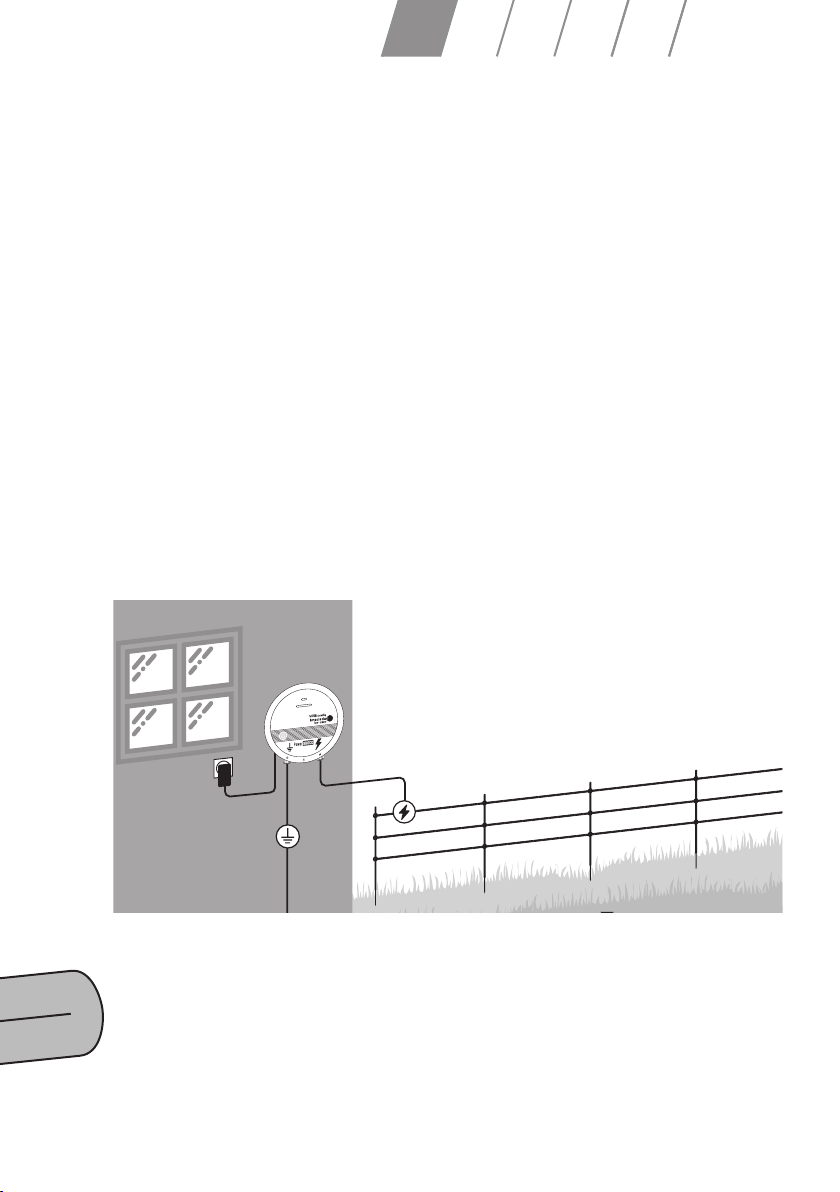
NOTE: Please choose a suitable location for your grounding system.
Your grounding system must be:
• at least 10 m away from other grounding systems, such as ground connections of
homes, telephone or power lines.
• away from animals or pathways as animals or people may damage the grounding.
• accessible to you at any time for maintenance purposes.
If you run any connection cables through the inside of buildings, you must always use
insulated high-voltage cables.
5. THE IDEAL FENCE
Regardless of the types of conducting material used in your fence, there are a few
things to keep in mind in order to ensure good conductivity.
• Keep your electric fence system free from vegetation. Do not run your fence through
hedges and avoid having any branches or bushes complete the circuit.
This will reduce the voltage on your fence and the shock strength of the electrical pulse
may no longer be powerful enough.
• Ensure that the conducting material in your fence does not touch the ground,
e.g. by sagging.
• Only use fence posts with insulators so as to insulate the conducting material from
the post and the ground. This will prevent any loss of voltage and ensure the desired
current ows through the conducting material of the fence.
Suitable accessories are available for using metal posts and industrial fences.
NOTE: It is a legal requirement to place warning signs on the fence in publicly accessible
areas, such as item no. 44735.

DE EN FR IT NL SE ES
6. Radio remote control (RF models only)
Our Impulse DUO RF energisers come with
a remote and an antenna to control, mana-
ge and operate your device remotely. The
eective range is up to 10 km depending on
topographical conditions.
1 sound
2 remote battery indicator
3 signal strength
4 update mode
(every minute or every hour)
5 value and unit of measurement
6 energiser battery indicator
7 identication number of the currently
selected energiser
8 power level indicator (half / full)
9 device type
10 choice between half / full power
11 alert button
12 info - manual update
13 energiser calibration <–> remote control
14 settings
15 switch remote on /o, step back
16 data selection
17 switch energiser on /o
battery compartment

GENERAL OPERATION
The Impuls DUO RF models work similarly to the Impuls DUO, but additional functions
have been added for communication between the energiser and the remote control.
If the energiser is completely switched o and no lights are seen, hardly any energy is
consumed. However, in this state the energiser cannot interact with the remote control.
RF models have a dierent switched o state in which the energiser is still ready to recei-
ve the signal from the remote control. In this state, the control LED ashes blue every
three seconds. If it ashes red, the battery charge is low. Use the main screen to control
the selected energiser.
The selection between the devices is made using the arrow keys. Use the display to check
the fence voltage (kV). If you want to display the supplied voltage (V) instead of the fence
voltage, press the „data selection“ button (16).
At the top right of the remote you will nd the energiser output button (10). With this
button you can adjust the energiser output: 100% or 50%. Your selection will be shown on
the display (8).
There are two power buttons on the remote. Hold down the red power button (15) and
turn the remote control on and o. Press and hold the energiser power button (17) to
turn the energiser on or o.
CALIBRATION MODE
Calibration mode assigns the energiser to a remote control.
• Turn the energiser ON, then OFF and then hold down the ON/OFF button on the
energiser for at least ve seconds. In the calibration mode, the control LED ashes blue
rapidly.
• Press and hold the calibration button on the remote control (13) until „P“ appears on
the display.
• Use the arrow keys to assign the energiser a desired identication number.
• Place the remote control near the energiser, within 20 cm or less, and press the calibra-
tion button (13).

DE EN FR IT NL SE ES
If the calibration fails, please try again.
If you want to unassign an identication number in the remote control, start the calibration
process, but without the energiser.
If the remote control does not nd the energiser, it deletes this position. To exit the
calibration mode, briey press the power button on the remote control (15). A remote
control can manage up to six dierent energisers. Conversely, an energiser can connect
to and be controlled by three dierent remote controls.
SETTINGS
To enter settings press continuously the setting button (14) on the remote control. There
are now three options available which you can cycle by pressing the settings button. Use
the arrow keys to make changes to the settings.

Letter „A“ - you can switch the alarm signal of your remote control on or o.
Under the letter „U“, select the interval for updating the data of your energiser. An empty
round arrow is an interval of 1 minute. A round arrow with an „i“ in the middle is an in-
terval of 1 hour (this consumes less energy and keeps your battery longer). For a manual
update, press „i“ on the remote control.
Lastly, you can set a limit for minimum voltage on the fence. As soon as the voltage falls
below it, an alarm is triggered on the remote control.
ALERTS
The alert will appear on the remote control as a ashing warning sign (the exclamation
point in the triangle). You will also hear a beep, as long as you have not muted it in the
settings.
No signal:
If the signal and warning signs are ashing, the signal is weak.
Low fence voltage:
If the voltage value ashes, the fence voltage is too low.
Electric fence battery charge low:
If the battery and alarm symbols are ashing, the battery is empty.
General alert:
If only the alarm symbol is ashing, there may be several possible causes for this. For
example, if there was a rapid change to the fence voltage, for example an animal, person
or a tree touches the fence.
To turn o the warning sound, press the alert button (11). The sound can also be swit-
ched o completely in the settings. If you have xed an error, press the alert button and
the error message will be deleted.

DE EN FR IT NL SE ES
7. INITIAL SETUP:
NOTE: The following steps will help you activate the energiser. Your fence will
then be live. Make sure that there are no people or animals near the fence.
When the energiser is connected to the fence it constantly checks for faults. If the LED
bar (4) is red, there is a fault on the fence. Meaning your fence security is compromised.
Check your fence for faults.
In order to achieve the best possible safety, the following minimum conductor spacing
is recommended:
140 cm
100 cm
50 cm
110 cm
85 cm
60 cm
40 cm
20 cm
105 cm
75 cm
45 cm
85 cm
60 cm
40 cm
20 cm
70 cm
40 cm
20 cm
120 cm
75 cm
45 cm
Horses
Goat
Cattle
Poultry
Domestic pigs
Pony
90 cm
65 cm
40 cm
20 cm
140 cm
105 cm
75 cm
45 cm
30 cm
Sheep
Deer

8. MAINTENANCE AND CLEANING
Always turn o the VOSS.farming impuls duo and unplug it from the mains when
performing maintenance and cleaning work. The unit does not require regular mainte-
nance, but you should inspect it visually on a regular basis. Check all cables and lines
for damage. Contact a specialist immediately to replace any broken parts or cables. Do
not operate the energiser if there is any damage. Keep the energiser clean by wiping it
with a slightly damp cloth.
9. SAFETY TIPS
Carefully read and observe the following before using the energiser:
This device may not be used by persons (including children) with physical, sensory or
mental impairments. Further, it may not be used by persons without sucient experi-
ence and specialist knowledge unless supervised or under guidance by another person
who is responsible for their safety. Children must always be supervised to ensure that
they do not play with the device. Electric fences must be installed and operated such
that there is no danger to people, animals and their surroundings.
Observe the following to ensure safe operation:
• Only use weaker energisers or outputs with limited pulse energy (1 joule) in areas
where unsupervised children may be present and on electric fences with alternating
polarity (positive/negative fences).
NOTE: Do not touch electric fence wires! Do not climb over, through or under fences
with several wires.
• Avoid using electric fences with alternating polarity in places where people may be
able to get between two wires of diering polarity. If you must use such a fence,
then use a weaker energiser (e.g. with a 1 joule limit) – even with non-electried,
grounded wire.
• Provide people with access through the fence to public paths using insulated gates,
gate handles or insulated crossing points (stiles) at all points where access is intended.
Always use a gate or access point that is specically intended for that purpose.
Access points along public paths and any other place where there are people
should be tted with warning signs about every 100 m.
• Keep a minimum distance of 2.5 m between the electric fence and grounded,

DE EN FR IT NL SE ES
metallic objects (such as water pipes and troughs), especially in areas where people
may be present.
• If there is a danger of ooding around the electric fence, stop using the energiser.
• If the pulse interval is less than 1 second, shut down the energiser immediately and
have it repaired if necessary. A pulse interval of over 1.6 seconds means that the
energiser is no longer providing sucient security and requires inspection.
This device meets the requirements of EC directive 2004/108/EC “Electromagnetic
Compatibility” (CE mark) and European safety standard EN 60335-2-76 (Electric Fence
Energisers).
Prevent misuse of the energiser by:
• Paying attention to markings on the device
• Securing it against unauthorised access (such as anti-theft protection, child
protection) if necessary in the installed location.
• Special use of electric fences in zoos or wildlife enclosures: Installation of such
systems may only be carried out by qualied electricians. A non-electric fence
must be present to separate visitors from the electric fence.
• If the mains connection lines to the energiser are damaged, then these must be
replaced by the manufacturer, the manufacturer’s customer services or another
similarly qualied person in order to avoid injury. Servicing and repairs may only
be carried out by authorised specialists! Only replacement parts authorised by
the manufacturer may be used.
OPERATING PRINCIPLE AND LIMITS OF ELECTRIC FENCES FOR ANIMALS
An electric fence consists of an energiser and an insulated fence. The energiser
supplies the fence with short electrical pulses. The electric fence presents a “physical”
and “psychological” barrier to animals. The short high-voltage pulses are very
unpleasant and animals will quickly learn to respect the electric fence.
A properly installed electric fence can provide a high level of safety and has many
advantages compared to a purely mechanical fence. As a psychological barrier, the
electric shock discourages animals from trying to get over the fence. Less work and

fewer materials are required, alterations are easily made, it is suitable for a very wide
range of animals and oers a great deal of protection against injury.
OPERATING PRINCIPLE OF THE ELECTRIC FENCE ENERGISER
The electric fence energiser emits an electrical pulse through the fence about once
every second. The pulse gives the animal a short, sharp, yet harmless shock. This is in
no way dangerous for the animal, but is enough that it will remember to avoid the fence
in future.
PRACTICAL TIPS
Check regulations for your local area before building a fence. You may require permis-
sion to do so. Regularly check the energiser to ensure that it is still functioning properly
by looking at the ashing indicator LED. Check the fence system regularly. Remove
any fallen branches, weeds or bushes as these may cause a short circuit and reduce
the eectiveness of the fence. All animals will need time to learn to respect the fence.
Training may take several days and you may need to make some small adjustments to
the fence.
Animals that can jump may be dicult to fence in. You may need to increase the height
of the fence in order to ensure maximum safety. Make sure to use high-quality insula-
tors. Cheap or cracked insulators and plastic tubes are not recommended as these can
cause short circuits.
Use connecting bolts for all steel wire connections to ensure a good circuit is made.
To ensure correct functionality of the electric fence, ground the energiser using
grounding posts made of galvanised metal. Use double-insulated cable inside build-
ings, under driveways and in places where any galvanised wires lying on the ground
may become corroded. Never use household electrical cables as these are designed
to carry 600 volts at most and a loss of current may occur.
ELECTRIC FENCE REQUIREMENTS
Electric fences and associated equipment must be constructed, operated and main-
tained such that there is no danger to people, animals and their surroundings. Electric
fences in which people or animals can get caught must be avoided. An electric fence
may not be supplied by two separate energisers or by independent fence circuits from
the same energiser.

DE EN FR IT NL SE ES
Where there are two separate electric fences, each supplied by a separate energiser,
the distance between the wires of the two fences must be at least 2.5 m. If this gap
between the fences must be closed o, then this must be done using non-conducting
materials or an insulated metal barrier. Barbed wire or sharp-edged wire may not be
electried by an energiser.
Observe the manufacturer’s recommendations for grounding the energiser.
A distance of at least 10 m must be kept between the grounding electrode for the ener-
giser and any other components connected to grounding systems (such as the ground
connections for power supply systems or telecommunications systems). Connecting
cables that run through buildings must be eectively isolated from grounded parts of
the building. This can be achieved using insulated high-voltage cables.
If connection cables and wires that are part of the electric fence must run near to
high-voltage lines, then they may not be installed more than 3 m above the ground.
This height applies to each side of a right-angled projection from the outer conductor
of the high-voltage cable on the area for a distance of
• 2 m for high-voltage lines that operate at a
rated voltage of up to 1000 V;
• 15 m for high-voltage lines that operate at a rated voltage over 1000 V.
Electric fences intended for scaring o birds, for keeping pets or training animals, e.g.
cows (cow trainer), should only be supplied by a low power energiser (which still has a
sucient and secure eect). Where an electric fence is intended to prevent birds from
nesting on buildings, no wire of the electric fence may be grounded if the fence wires
are not connected to metal parts.
If a wire is connected to a metal part (such as gutter) or a metal structure in the build-
ing, then this metal part must be grounded. A warning sign must be attached at all
points where people are able to access the conductors.
Where an electric fence crosses a public footpath, a non-electried gate or stile must
be present. Each of these stiles must be tted with warning signs indicating that the
fence is an electric fence. Each part of an electric fence that runs along public streets
or other public rights of way must have warning signs securely attached to the fence
posts or wires at regular intervals. Connecting wires that run below the ground must
be placed inside protective insulated pipes or insulated high-voltage cables must be
used. It is important to ensure that connecting cables cannot be damaged by external

inuences (such as animal hooves, tractor wheels, etc.) that sink into the soil. Connecting
lines may not be installed in the same protective pipes as mains and supply cables,
communication or data lines.
Connecting cables and wires belonging to electric fences may not be laid above high-
voltage or communications cables. Crossing high-voltage cables should be avoided.
If crossing over a high-voltage cable cannot be avoided, then the cable must be laid
below the high-voltage cable and be as close to a right-angle with it as possible.
Warning signs must be at least 100 x 200 mm in size. The background colour on both
sides of the warning sign must be yellow. The text on the warning sign must be black.
The text must read “Warning: Electric Fence” or similar. The text on the warning
sign must printed in a durable way and be at least 25 mm in height. Ensure that all
mains-powered supporting equipment connected to the electric fence circuit has a
degree of insulation between the fence circuit and mains supply which corresponds
to that of the energiser.
10. DISPOSAL
If you wish to dispose of the energiser, please contact a local disposal company or
recycling centre. Alternatively, you may contact your authorised specialist dealer VOSS
GmbH & Co. KG. All consumers are legally required to properly dispose of old electronic
devices. Please do not dispose of the energiser with your normal household waste! This
helps make a valuable contribution to protecting our environment.
POSSIBLE DANGERS
Electric fences, especially those for livestock, are generally safe with proper installation
and connection. Electric fences, however, can cause shocks that can lead to dangerous
consequences, especially for people with existing health problems. Knowing the dan-
gers of electric fences can help you take necessary precautions.
Head injury
If you climb under an electric fence, you can receive an electric shock to your head
when it comes into contact with the fence. A person with heart disease, especially
someone who wears a pacemaker, has a higher risk of becoming unconscious than a
healthy person. The risk increases when the head or neck touches the electried wire.
This manual suits for next models
6
Table of contents
Other VOSS.farming Power Supply manuals