Lumel HA-PSA3515 User manual

PROGRAMMABLE DC POWER SUPPLY
HA-PSA3515
USER’S MANUAL

User’s Guide
Programmable DC Power Supply
09/2015

Programmable DC Power Supply User’s Guide
1
Introduction of Programmable DC Power Supply
Programmable power supply is a new generation of programmable DC power supplies of
our factory. The power supply has RS232 programmable interface and optional USB
interface, digital nixie tube, LED and indicator light to show working status, key light
shows setting status. Double digital knobs and keypad are supplied to set parameters,
while using of the adjusting knob, user can directly set the voltage and current and don’t
need to switch the key and knob. The built-in function module, controlled by 32 bits MPU,
use CAN bus-mastering to supply the reliable output and over-load hardware protection,
the step of over-load protection is adjustable and could be selected to be on or off. Except
of this, power supply also protect itself by warning and cutting off output once fun
controlling module gets fault, transistor over-heating, internal bus gets fault. It is of
programmable CV/ CC adjustable step. The two working states, CV and CC, can be
switched varying with the load. Meantime, the external voltage sampling terminal is
supplied to output stable voltage for user load within the range of wire voltage drop.
Programmable power supplies are widely applied in national defense, institution,
university and factory, especially in the areas of computer measuring and automatic
control system as DC power supply.
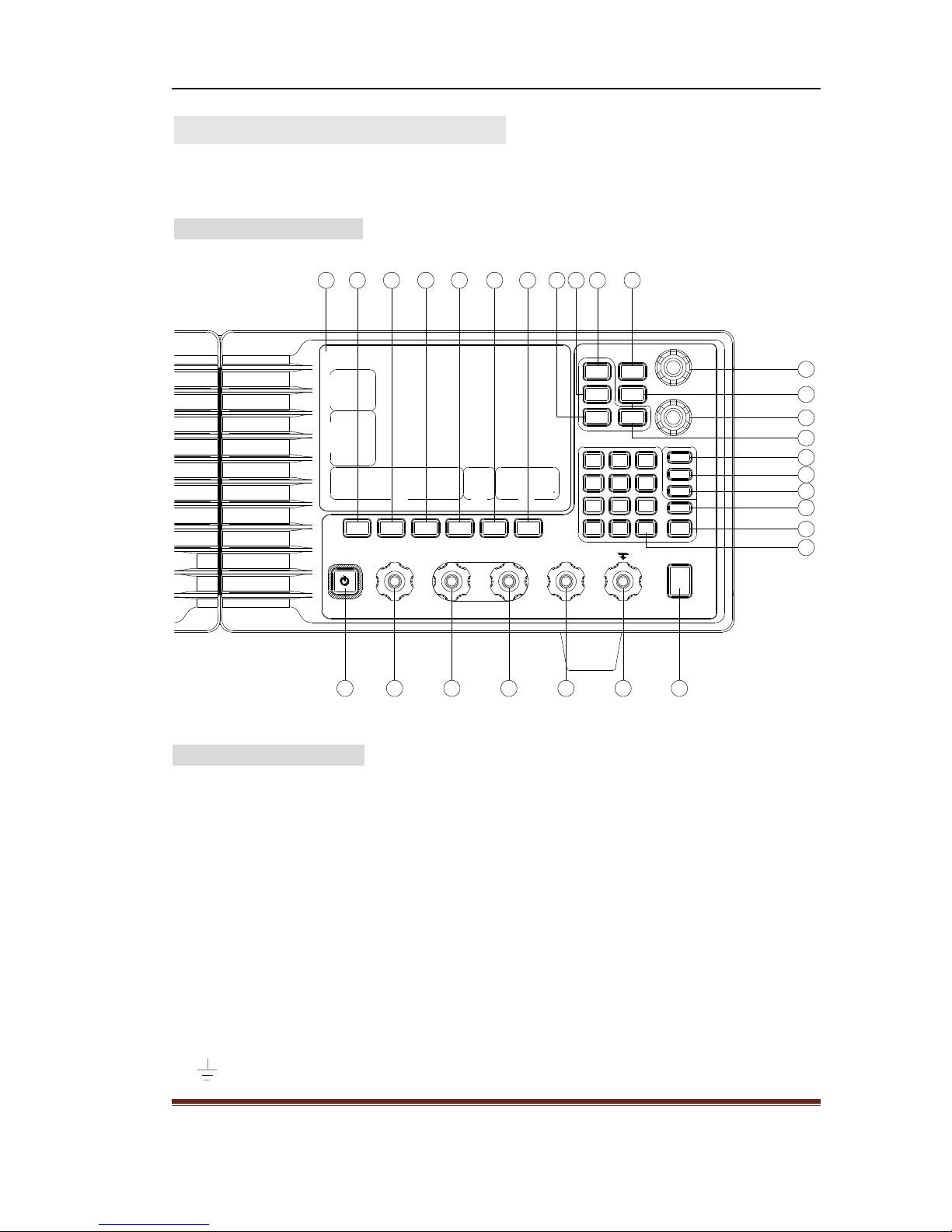
Main function characteristics
All digital control, inside CAN bus controlling, low drift and high resolution
Nixie tube + LED + Key Indicator to show working state, clarity and simple
User-defined storage/recall function
Adjust by digital knob roughly or finely. Convenient setting and direct output
Keypad lock function, to avoid the misoperation
Hardware of OVP (Over Voltage Protection), setting is adjustable and ON/OFF also
could be selected.
Distanced wire voltage drop compensate, ON/OFF available
Temperature fan controlling, with warning of fan/over heat/fault of internal module
Standard configuration: RS232 interface
Optional configuration: USB device

Programmable DC Power Supply User’s Guide
2
Packing List
Programmable Power Supply 1
Power Cord 1
CD (User’s Guide) 1
RS232 interface cable 1
Optional
USB interface and cable 1

Programmable DC Power Supply User’s Guide
3
Content
Chapter 1 Prepare to use power supply------------------------------------------4
1.1 Check the list of supplied items ---------------------------------------------------------------4
1.2 Connect the power -------------------------------------------------------------------------------4
Chapter 2 Operation Instruction--------------------------------------------------5
2.1 Front panel overview ---------------------------------------------------------------------------5
2.2 keyboard instruction ----------------------------------------------------------------------------5
2.3 Display screen overview -----------------------------------------------------------------------8
2.5 Connection of load and tips --------------------------------------------------------------------8
2.6 Effect of load to power supply ---------------------------------------------------------------10
2.7 Operation attention -----------------------------------------------------------------------------11
2.8 Basic Operation --------------------------------------------------------------------------------13
Chapter 3 Programmable Interface---------------------------------------------16
3.1 To set series port----------------------------------------------------------------------------16
3.2 Programmable commands---------------------------------------------------------------------16
Chapter4 Maintenance--------------------------------------------------17
Chapter 5 Service and Support--------------------------------------------------18
Chapter 6 Specifications -----------------------------------------------------------19
Notice: please excuse any modification of the contents without special notification.
Besides, it is unavoidable for not-so-adequate description and wrong printing. The present
document will not warrant in any form including, but not limited to, those for special
aims.

Programmable DC Power Supply User’s Guide
4
Chapter 1 Prepare to use
1.1 Check the list of supplied items
Check whether the meter and the accessories are complete and ready. If the package is
badly damaged, please keep it until the meter passes the performance testing.
1.2 Connect the power
To guarantee the safe operation of the meter, the following conditions should be achieved.
Voltage:115 (1100~125)V
230(200~250)V
Frequency:50 (45~60 )Hz
Working Environment: Indoor
Temperature: 0~40℃
Relative humidity: 20% ~ 90%RH (40℃)
Insert the power plug into the power socket with AC voltage 115V or 230V and earthing
wire, then press the power switch on the panel to make the device connected to power
source. Now the initialization of the power supply begins.
Warning: in order to ensure the security of the operator, triple- core socket outlet
with the safe earthing wire must be used.

Programmable DC Power Supply User’s Guide
5
Chapter 2 Operation Instruction
User will get detail learning about functions and usage of the power supply through this
chapter.
2.1 Front panel overview
Unlock Prot Clear
Control
Output
S+ + - S-
Recall
Save
Sense
RPG
Coarse
Enable
RPG
Prot
Enable
Volt
Curr
O.V.P
Cancel
Enter
7 8 9
654
1 2 3
←
.
0
Shift Rmt Local Addr Lock Beep
ON
t
S
t
a
p
s
i
D
Cali FailProt
Unreg
FCM
ACMTSen
Fan
OTP
OVPOV
HPLP
Curr
Volt
ZPErr
Ena
Err
CC
CV
Output
Prot.set
Setting
128 27 26 25 24 23
2 3 4 5 6 7 8
9
11
13
16
18
14
12
10
17
15
19202122
VOLTAGE
CURRENT
POWER SUPPLY
PROGRAMMABLE
V
A
2.2 Keyboard Instruction
(1) LCD: Display the value of voltage/current, output the value of voltage/current and
setting state, display the state.
(2)【POWER】: Power switch, press it to connect AC power. Press again to select stand by.
(3) S+: positive output terminal of external sampling, to compensate the voltage drop
caused by wire resistance
(4) +: Positive output terminal
(5) -: Negative output terminal
(6) S -: negative output terminal of external sampling, to compensate the voltage drop
caused by wire resistance.
(7) : earthling.

Programmable DC Power Supply User’s Guide
6
(8) Output Control: dc output switch, to control the output status of power supply, default
is off. Press the key to enable the output and light on. Press again to disable the output
and lighter off.
(9) Numeric keys: to input data, 【←】backspace key to delete the input data
(10) 【ENTER】: enter key. The light on indicates the key is available. Press the key to
confirm the input and save, the light off.
(11) 【Cancel】: cancel key. The light on indicates the key is available. Press the key to
cancel the input, the light off.
(12) 【O.V. P】: to set over voltage protection limitation. Press the key with light on,
which indicates the present data input will be saved, the unit is V. when finish the data
input, the light is off.
(13) 【Currr】: to set output current. Press the key with light on, which indicates the
present data input will be saved, the unit is V. when finish the data input, the light is off.
(14)【Volt】: to set output voltage. Press the key with light on, which indicates the present
data input will be saved, the unit is V. when finish the data input, the light is off.
(15) 【Pro Enable】: to enable the OVP function. Press the key to enable the over voltage
protection with light on. Press again to disable the function, the OVP function is disabled
and light is off. The status of key was saved in memory and kept on next power on.
(16) Current adjusting knob: to adjust the output current.
(17) 【RPG Coarse】: coarse adjusting knob enabled key, the step of which is 0.1V/0.1A.
Press the key again to select fine adjusting, the step of which is 1mV/mA.
(18) Voltage adjusting knob: to adjust the output voltage.
(19)【RPG Enable】: knob enabled key, the step of which is controlled by【RPG Coarse】
function key. Press again to disable the knob adjusting.
(20) 【Recall】: to recall the preset. Press the key to recall the saved data (series number),
according parameter saved under the series number will be recalled after pressing of
【ENTER】key. Or press【Cancel】key to return the former status.
(21) 【Save】: to save the preset. Press the key to show the series number of storage data,
according parameter saved under the series number will be recalled after pressing of
【ENTER】key. Or press【Cancel】key to return the former status. After data input, the

Programmable DC Power Supply User’s Guide
7
indicator lights off.
(22) 【Sense】: remote compensation controlling key. Press the key to enable the remote
compensation to control output voltage with light on. Press again to disable the mode. The
status of key was saved in memory and kept on next power on.
(23)【Beep】(Prot Clear): beep on/off. Press the key to enable the beep function with light
on. Press again to disable the beep function with light off. Second function: clear the over
voltage protection.
(24) 【Lock】(Unclock): to lock the keypad. Press the key to lock all the keys except of
【Shift】key. Second function: press 【Shift】and 【Lock】keys to unlock the keys.
(25) 【Addr】: Idle.
(26) 【Local】: to select local controlling.
(27) 【Rmt】: to select remote controlling, the key setting will be saved in memory, and
kept when next power on.
(28) 【Shift】: to select second function of keys. Press this key to enable the second
function with light on, which should be preferred together with the multifunctional keys.
Press other key to exit this shift key and the indicator light off.

Programmable DC Power Supply User’s Guide
8
2.3 Display screen overview
t
S
t
a
p
s
i
D
Cali FailProt
Unreg
PROGRAMMABLE
POWER SUPPLY
FCM
ACMTSen
Fan
OTP
OVPOV
HPLP
Curr
Volt
ZPErr
Ena
Err
CC
CV
Output
Prot.set
Setting
1
2
3
4
5
6
7
8
9
22
23
1110 1213 1415 1617 1819 2021
A
V
2.4 Display screen instruction
(1) Indicator of output settings, when it’s on, the data displayed is the setting of output
voltage and current.
(2) Indicator of protection settings, when it’s on, the data displayed is the over voltage
protection setting.
(3) Indicator of monitoring data, when it’s on, the data displayed is the real-time output
voltage and current.
(4) Indicator of CV mode selected for working with light on
(5) Indicator of CC mode selected for working with light on
(6) Alarm indicator of failure to output as preset, which indicates that the real output
voltage/current available up to requirements, that maybe caused by over-low input voltage,
or wire load, or damaged power unit inside, and the power supply have to be repaired.
(7) Alarm indicator of failure to CC/CV controlling circuit, which indicates that the power
supply getting fault and the output voltage/current out of preset range, or damage to logic
controlling circuit and have to be repaired.
(8) Indicator of calibration, the procedure only processed in factory.
(9) Alarm indicator of error in calibration, the procedure only processed in factory.
(10) Indicator of voltage calibration, the procedure only processed in factory.

Programmable DC Power Supply User’s Guide
9
(11) Indicator of zero calibration, the procedure only processed in factory.
(12) Indicator of current calibration, the procedure only processed in factory.
(13) indicator of low point calibration, the procedure only processed in factory.
(14) Indicator of OVP calibration, the procedure only processed in factory.
(15) Indicator of high point calibration, the procedure only processed in factory.
(16) Indicator of VOP protection, which indicates that the OVP protection is working and
output is shut off. The output key is disabled until press the cancel key to cancel the OVP
protection.
(17) Alarm indicator of over-heat protection, which indicates the power over-heat event
happened and output is shut off. user need to restart the power supply and turn on the
output. If the temperature normal when power on again, the power supply go on working,
otherwise the output will be shut off again.
(18) Error indicator of temperature sensor, the power supply goes into protection with
output disabled, and need to be repaired.
(19) Failure indicator of fan, which indicates that the fan does not work as required speed.
The output is disabled and has to be repaired.
(20) Failure indicator of analog controlling system, which indicates that the bus cannot
communicate with analog controlling module, it fail to receive the commands and need to
be repaired.
(21) Failure indicator of fan controlling module, which indicates that the bus cannot
communicate with fan controlling module, it fail to receive the commands and need to be
repaired.
(22) Data display area 2, where show current settings when using knob and saved preset
when using numeric keys.
(23) Data display area 1, where show voltage settings when using knob and present
settings when using numeric keys.
2.5 Load connection and attention
2.5.1 Common connection of load without sense function

Programmable DC Power Supply User’s Guide
10
When sense function not preferred, terminal S+ and S- should be idle, cannot be
connected with any other component and wire, or else cause the output voltage error to
power supply.
2.5.2 Common connection of load with sense function
When sense function preferred, terminal S+ and S- are required to be right connected with
load + /- polarity accordingly. If make wrong connection, the power supply output wrong
voltage and probably to burn up the load. There is less current between the wire of S+ and
S-, but maybe some interruption, which will increase the ripple voltage on load. To get
best ripple voltage result, user is suggested to twist the S+ and S- wires for shielding.
2.5.3 Common connection of load (Battery) without sense function

Programmable DC Power Supply User’s Guide
11
When storage battery is used as load, user must connect a diode to avoid current contra
flow in circuit, the support current of diode is required to match with the output current of
power supply at normal working, or else it will be burn out. And do not make the wrong
connection to battery polarity, or else the power supply will be burn out.
2.5.4 Common connection of load (Battery) with sense function
When storage battery is used as load, for long output cable, user can relieve the voltage
drop with sense function, the connection of which is shown as figure. And user must
connect a diode to avoid current contra flow in circuit, the support current of diode is
required to match with the output current of power supply at normal working, or else it
will be burn out. And do not make the wrong connection to battery polarity, or else the
power supply will be burn out.
2.6 The influence of load
2.6.1 Maximum capacitance of load
Once OVP function disabled, load capacitance will lead to phase lag to power supply due

Programmable DC Power Supply User’s Guide
12
to its closed circle system. When capacitance is large enough, the phase lag is easy to
cause the shock to power supply itself, to avoid this, the capacitance should be limited
within 22000μF.
Once the OVP function enabled, the one-way thyristor serves as discharge component in
over voltage protection circuit, the triggering of OVP will cause the thyristor breakover
and release the stored energy in load capacitor. Once the total capacitance released from
load and power supply internal over the support ability of thyristor, the component
probably be damaged, to avoid this, the maximum capacitance should be limited within
10000μF.
For operator using of over capacitance load and cause the damage to thyristor,
the maintenance is chargeable according to actual condition.
2.6.2 When load is storage battery
The diode connected in anti-parallel at output terminal of power supply could support
15A current at most. Also the one-way thyristor serves as the discharge component in over
voltage protection circuit at output terminal. If the voltage of OVP set lower than battery
and OVP is enabled, the thyristor is probably to breakover and cause the huge short
current to burn out the mainboard. So to protect the power supply and battery, user should
connect one diode to prevent the contra flow current when you select storage battery as
load. The capacitance of diode should match with the max output current, or else it will
cause the diode over heat and burn out. Also do not make the reverse connection to
battery to avoid the damage to diode and current sampling resistance.
For the damage of power supply caused by user wrong operation, the maintenance is
chargeable.
2.7 Attention to operation
2.7.1 The using of OVPfunction
The function can be enabled or disabled as user demand, the value of which is also can be
set. The wrong setting may cause the protection not work and output not normal. So user
should set over voltage protection parameter according to actual condition.
OVP circuit makes the direct measurement to the voltage of output terminals internally
without S+ and S- terminals, if user make mistake to connect them, the monitoring
voltage probably get wrong, which is not so accurate (a little higher). So considering the

Programmable DC Power Supply User’s Guide
13
accuracy of OVP setting impossible reach to output voltage, please make a allowance
during operation. Incorrect setting of OVP will lead to error action to power supply, or the
OVP does not work when voltage of power supply over the bearable voltage of load.
2.7.2 The using of sense function
S+ and S- terminals are used for sample the load voltage and stabilize it according to
sampled voltage parameters, to lower the voltage drop to minimum and ensure the load
voltage stability. Wire resistance is required less than 100mΩ, if too high, the wire
resistance and load capacitance make up a low-pass RC filter, taking phase lag to output
and lead to instability, also bring in interference.
When S+ and S- terminals connected to circuit (enable the sense function), please turn on
the sense function, otherwise the output voltage will get lower.
When S+ and S- terminals are idle (disable the sense function), please turn off the sense
function, otherwise the output voltage will get higher.
2.7.3 The requirement to AC power supply
For the high power of this unit, the transformer at power-on will get a short saturation and
periodic shock current, using the lighting air switch (C type release characteristic) may
cause switch trip at power-on. A dynamic air switch (D type release characteristic) is
advised for offer the AC power source, the capacitance of which should not less than 16A.
2.8 Basic Operation
2.8.1 Setting of output voltage
Method 1: Use the number keys to set. Press【Volt】key, then enter voltage value by the
number keys on the front panel. Press the key of 【ENTER】to save the setting. So the
voltage value in the interface is the entered value.
For example:Set the voltage value to be 32.00V.
Press the keys of【Volt】【 3】【 2】【 .】【 0】【 0】【0】【ENTER】in turn.
Method 2: Use the knob to set. Pressing the key of【RPG Enable】, and the voltage value
will be varied with the rotating of the knob. Press【RPG Coarse】key to change step.
2.8.2 Setting of output current
Method 1: Use the number keys to set. Press【Curr】key, then enter current value by the
number keys on the front panel. Press the key of 【ENTER】to save the setting. So the

Programmable DC Power Supply User’s Guide
14
current value in the interface is the entered value.
For example:Set the current value to be 11.000A.
Press the keys of【Curr】【 1】【 1】【 .】【 0】【 0】【 0】【 ENTER】in turn.
Method 2: Use the knob to set. Pressing the key of【RPG Enable】, and the current value
will be varied with the rotating of the knob. Press【RPG Coarse】key to change step.
2.8.3 Setting of OVP
Method 1: Use the numeric keys to set. Press【O.V. P】key and then numeric keys to set
the OVP value, finally press【ENTER】key to save the settings.
For example: set the OVP to 32.000V.
Press 【O.V.P】【 3】【 2】【 .】【 0】【 0】【 0】【 ENTER】.
Method 2: Use the knob to set. Pressing the key of 【RPG Enable】, and the OVP
value will be varied with the rotating of the knob. Press【RPG Coarse】key to change step.
2.8.4 Setting of output voltage
While press the 【OUTPUT】key under presetting, the output is enabled, the current
output voltage and current are displayed on screen. If press the key again, then back to
preset status, the output is disabled, the current settings are displayed.
2.8.5 To set the remote control mode
Press 【RMT】key to select remote control mode for device through the RS232 or
USB interface.
2.8.6 To set local mode
Press 【Local】key again to select local mode for device, which is controlled by
keypad operation.
2.8.7 To lock the keypad
Press 【Lock】(Ulock)key to enable the lock function. Press 【SHIFT】+【Lock】
key to disable the lock function and all keys come back to its function.
2.8.8 Beeper On/Off
Press 【Beep】(Prot Clear) to enable the beeper. Press the key again to close the
beeper.
2.8.9 To clear the OVP
While the device enter into the OVP function, press 【SHIFT】+【Beep】(Prot Clear)

Programmable DC Power Supply User’s Guide
15
key to clear the OVP function, the indicator lights off.
2.8.10 To enable the OVP function
Press【Prot Enable】to enable the protection. Press the key again to disable the protection.
2.8.11 To enable/disable the knob adjusting
While press the 【RPG Enable】, user select adjusting knob to set the value, the step of
which is decided by 【RPG Coarse】key. Press 【RPG Enable】key again to exit the
knob setting.
2.8.12 To set the adjusting knob
Press【RPG Coarse】to select 0.1V/0.1A as step for knob adjusting. Press the key
again to select 1mA/1mA as step for adjusting knob.
2.8.13 To recall the presetting
Press 【Recall】key to enter the storage address 1 to 6, then recall the saved
settings by pressing of 【ENTER】key.
2.8.14 To save the presetting
Press 【Save】key to enter the storage address 1 to 6, then save the present
settings to desired address by pressing of 【ENTER】key.
2.8.15 To set the sense function
Press 【Sense】key to control the output voltage by remote compensation mode.
Press the key again to exit the sense function and device return to normal output
mode.

Programmable DC Power Supply User’s Guide
16
Chapter 3 Programmable Interface
Press 【RMT】to enter remote control mode.
3.1 To set the series port
Baud Rate: 9600, Check: No parity, Word Length: 8, Stop bit: 1
3.2 Programmable Commands
SCPI Commands
Description
*IDN?
Query the device identification
Return HA-PSA3515,BJA5.297.556, firmware
version
SYSTem:VERSion?
Query the device firmware version, Return the
version number
:LOCal
To set local control mode, return 1
VOLTage <NRf>
To set output voltage
MINimum
MAXimum
:PROTection <NRf>
:CLEar
CURRent <NRf>
MINimum
MAXimum
OUTPut OFF
ON
OUTPut?
MEASure?
MEASure:CURRent?
:MINimum?
:MAXimum?
To output minimum voltage
To output maximum voltage
To set OVP
To clear the OVP
To set output current
To output minimum current
To output maximum current
Turn off the output
Turn on the output
Query output status, Return 1, 0
Query all voltage/current
Query current
Query minimum current
Query maximum current
:VOLTage?
MINimum?
:MAXimum?
:PROTection?
Query voltage
Query minimum voltage
Query maximum voltage
Query OVP value

Programmable DC Power Supply User’s Guide
17
Chapter 4 Maintenance
4.1 Cleaning
In the case of disconnecting of power, the apparatus can be cleaned by soft cloth with
neutral washing liquid and clear water. It is forbidden to spray the washing liquid directly
on the apparatus in case that the apparatus is damaged resulted from the leaking.
4.2 Daily maintenance
For safety, the following instructions are only for professional technicians.
4.2.1 Replacing of fuse
If the apparatus cannot work properly because that the fuse is burnt out, first find the
reason and correct, and then replace the fuse according to the original model. It is
forbidden to use a temporary one or to short meeting the fuse block.
4.2.2As the apparatus is in malfunction and needs to repair, disconnect the power.
Warning:To insure the effective protection,only specific model fuse with the rating
of 250V can be replaced. The power must be disconnected before replacing. And the
power wire must also be taken off.

Programmable DC Power Supply User’s Guide
18
Chapter 5 Service and support
5.1 Warranty
We will give one year’s warranty to maintaining or replacing since consignment for the
verified quality problem of the product.
Except for this explanation and the description in the warranty card, the company has no
other warranty, in proclamation or in implication. Under no circumstances, the company
will responsible for the direct, indirect or other secondary loss.
Table of contents
Other Lumel Power Supply manuals