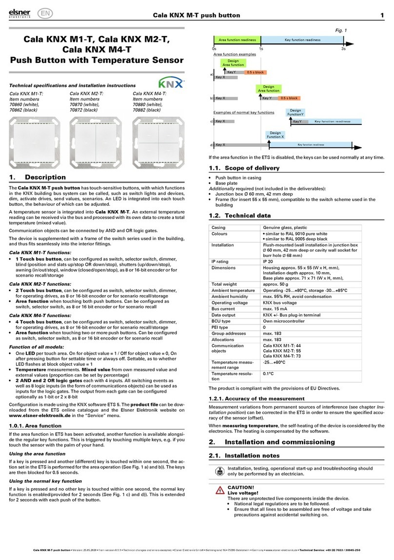
Elsner Corlo Touch KNX 5in User manual

Display Corlo Touch KNX 5in 1
Display Corlo Touch KNX 5in • Version: 06.04.2020 • Technical changes and errors excepted. • Elsner Elektronik GmbH • Sohlengrund 16 • 75395 Ostelsheim • Germany • www.elsner-elektronik.de • Technical Service: +49 (0) 7033 / 30945-250
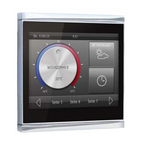
Corlo Touch KNX 5in (WL)
Display and Touch Switch
Technical specifications and installation instructions
Item numbers 70475 (Corlo Touch KNX 5in WL), 70481 (Corlo Touch KNX 5in)
1. Description
The Display Corlo Touch KNX 5in for the KNX system offers a variety of options
for its use: Its touch-sensitive glass interface means that it can be used as a normal
switch. The high resolution display is ideal for displaying text, images or graphics.
In addition to current readings and messages, the KNX bus system can also display
photographs, for example. Concurrently, you can set up the Corlo Touch KNX
5in as a control center for automatic shading, ventilation and air conditioning re-
gulation.
With the Corlo Touch KNX 5in WL model, you can also show network content
on the display using the WLAN connection, e.g. web pages, IP camera images or
visualizations. The Corlo Touch KNX 5in WL display screen can, for example, be
shown on a Smartphone, if a VPN connection is provided externally.
Functions:
• 5" touch-sensitive interface
•10 display pages, which can be configured with different areas for control
or display purposes, for example switches, buttons, rocker switch, rotary
knob, readings
With the Corlo Touch KNX 5in WL model, you can display predefined web
pages using the WLAN connection. You enter URL addresses in the ETS
• Icons for display can be exchanged (symbol library in the device, own
pictures from by micro SD card)
•Ambient lighting with individually variable colors (RGB)
• Integrated proximity sensor. Enables proximity switching and fast
activation of the display from standby mode
• Integrated brightness sensor for automatic adjustment of the display
lighting
• Integrated scene control(16 scenes), timer, alarm clock
•5 automatic channels, integrated automation for ventilation
(windows, ventilation equipment), for shading (shutter, blinds, awning) for
air conditioning regulation (heating, cooling) and for light
•4 AND and 4 OR logic gates each with 4 inputs. 16 logic inputs (in the
form of communication objects) are available as inputs for the logic gates.
The output of each gate can be optionally configured as 1-bit or 2 x 8-bit
•4 inputs for binary contact or temperature sensor
•Micro SD card socket e.g. as storage for image data
•Corlo Touch KNX 5in WL model: WLAN interface for wireless data
transfer from or into local networks. Due to limited system resources,
intensive use can lead to delays when loading the content.
Configuration is made using the KNX software ETS. The product file can be dow-
nloaded from the Elsner Elektronik website on www.elsner-elektronik.de in the
“Service” menu.
1.1. Deliverables
• Display unit with mounting unit and fixing screw
• Connection line
Optional accessories:
(not included in the deliverables):
• T-NTC temperature sensor (No. 30516)
• Micro SD card for image data (off the shelf)
1.2. Technical data
The product conforms with the provisions of EU guidelines.
1.3. Customizing options
1.3.1. Colours for display edge and housing
The standard colour for the display edge and housing is glossy black. Special
paints are possible, e. g. to RAL or automobile paint colour codes. Please ask for
your desired colour.
The glass pane is only available with black painting, special colours are not possi-
ble.
2. Installation and start-up
2.1. Installation notes
Installation, testing, operational start-up and troubleshooting should
only be performed by an electrician.
CAUTION!
Live voltage!
There are unprotected live components inside the device.
• National legal regulations are to be followed.
• Ensure that all lines to be assembled are free of voltage and take
precautions against accidental switching on.
• Do not use the device if it is damaged.
• Take the device or system out of service and secure it against
unintentional use, if it can be assumed, that risk-free operation is
no longer guaranteed.
The device is only to be used for its intended purpose. Any improper modification
or failure to follow the operating instructions voids any and all warranty and gua-
rantee claims.
After unpacking the device, check it immediately for possible mechanical damage.
If it has been damaged in transport, inform the supplier immediately.
The device may only be used as a fixed-site installation; that means only when as-
sembled and after conclusion of all installation and operational start-up tasks and
only in the surroundings designated for it.
Elsner Elektronik is not liable for any changes in norms and standards which may
occur after publication of these operating instructions.
2.2. Installation
2.2.1. Assembly site and assembly preparations
The device must only be installed and operated in dry, indoor
spaces. Avoid condensation.
ATTENTION!
The WLAN range for the Corlo Touch KNX 5in WL model can
be reduced as a result of the position where it is installed.
Consider this when planning the location.
Avoid direct light (sunlight, lights) when choosing the assembly site. The proximity
sensor's function can be impaired by strong light sources.
Choose the assembly height based on the application in each case: When used as
a switch, the Corlo Touch KNX 5in should be mounted 110 cm above ground le-
vel and when used as an indicating and control display, at a conveniently legible
height, say 150 cm.
The Display Corlo Touch KNX 5in is installed in a junction box (R 60 mm, depth
42 mm).
2.2.2. Wall mounting
Connect KNX bus, auxiliary voltage and where required the connection line inputs
to the display unit.
Housing Glass: real glass, tempered
Housing: plastic
Display Visible diagonal: 5 inches
Resolution: 800 × 480 pixel
Viewing Angle: 12 o’clock viewing direction
Opening angle x: -70° to +70° typ.
Opening angle y: -60° to +60° typ.
Colours • Black glass, edge glossy black
• Custom colours on request (see
“Colours for display edge and housing” auf
Seite 1)
Assembly Flush mounting
(Wall installation in junction box Ø60 mm)
Dimensions Housing overall approx. 133 × 97 × 35
(W × H × D, mm), Mounting depth approx. 20
mm
Weight display unit
Corlo Touch KNX 5in
approx. 200 g
Weight display unit
Corlo Touch KNX 5in
WL
approx. 210 g
Ambient temperature Operation 0...+50°C, storage -10...+50°C
Ambient humidity max. 95% RH, avoid condensation
Operating voltage 21,6…26,4 V DC.
A suitable power pack can be purchased from
Elsner Elektronik.
Bus current approx. 10 mA
Power consumption
Corlo Touch KNX 5in
• approx. 2.7 W maximum (when ambient
lighting 100% white, display brightness
100%)
• approx. 2.0 W in normal operation (when
ambient lighting off, display brightness 50%)
• approx. 1.4 W in standby operation (when
ambient lighting off, display off)
(was measured with 24 V auxiliary voltage)
Power consumption
Corlo Touch KNX 5in
WL
• approx. 3.5 W maximum (when ambient
lighting 100% white, display brightness
100%)
• approx. 2.4 W in normal operation (when
ambient lighting off, display brightness 50%)
• approx. 1.9 W in standby operation (when
ambient lighting off, display off)
• During startup briefly approx. 4.8 W (200
mA)
(was measured with 24 V auxiliary voltage)
Data output/
bus communication
KNX +/- Bus connector terminal
BCU type unit's own microcontroller
PEI type 0
Group addresses max. 1024
Assignments max. 1024
Communication objects 1022
Other data interfaces Micro SD
Inputs 4× Analog/digital,
max. cable length 10 m
Setting range of tempe-
rature sensor T-NTC at
input of Corlo Touch
-40°C...+80°C
Supported WLAN Stan-
dards Corlo Touch KNX
5in WL
IEEE802.11b/g/n, 2.4 GHz or 5 GHz
Supported WLAN Secu-
rity
Corlo Touch KNX 5in
WL
64/128-bit WEP, WPA-PSK, WPA2-PSK
Fig. 1
A socket with 4 screw domes faciliates in-
stallation.
Fig. 2
Bolt the mounting unit on to the socket.
The arrow („TOP“) must point upwards.
Two screws (right/left or top/bottom) are
enough.
TOP
Fig. 3
If the screw domes of the box used are
not covered with the mounting unit's lon-
gitudinal holes, the mounting unit can al-
ternatively be bolted via the other holes
(e.g. for other installation systems).
Fig. 4
Example: Boxes from Swiss systems.
Fig. 5
The display unit can now be put in place.
The arrow placed on the back („TOP“)
must point upwards.
Fit the display unit at the top first and
then engage it at the bottom.
Fig. 6
Fix the display unit from below with the
supplied screw (A).
A
Fig. 7
To remove the display unit from the
mounting unit, loosen the screw (A).
Press against the lower notches (B) to re-
lease the connection. The display unit can
be removed.
A
BB
EN

Display Corlo Touch KNX 5in 2
Display Corlo Touch KNX 5in • Version: 06.04.2020 • Technical changes and errors excepted. • Elsner Elektronik GmbH • Sohlengrund 16 • 75395 Ostelsheim • Germany • www.elsner-elektronik.de • Technical Service: +49 (0) 7033 / 30945-250
2.2.3. Connection overview
Connect the bus voltage (no. 6, red/black terminals) and auxiliary voltage (no. 2,
yellow/white terminals).
Use the attached breakout cable for connecting the digital/analog inputs (no. 8).
The cables for the inputs can be extendet to up to 10 m. All GND connections of the
inputs are bridged internally (black cable).
2.3. Instructions for assembly and operational start-up
Never expose the sensor to water (e.g. rain) or dust. This can damage the electro-
nics. You must not exceed a relative air humidity of 95%. Avoid condensation.
After the operating voltage has been applied, the device will enter an initialisation
phase lasting a few seconds. During this phase no information can be received or
sent via the bus.
3. Addressing the device
The programming mode for addressing at the bus is activated via the programm-
ing button at the back of the housing or via the display.
Settings > System > Service > KNX
4. Setting up the WLAN connection
Only for the Corlo Touch KNX 5in WL model with an interface for wireless net-
work connection!
4.1. WLAN settings in the ETS
The WLAN connection must be set up in the ETS. Consult the WLAN setting section
in the manual
ETS:System Settings > WLAN
2.13.1 WLAN
You set the network name and the encryption for compatibility with the WLAN net-
work access point. The IP address allocation can be made either automatically by
DHCP or manually.
Please note: If an automatic change depending on the quality of the connection
between 2.4/5 Ghz should be possible, you have to set up in the wireless router the
same Wi-Fi name with the same Wi-Fi password for both frequencies. Otherwise,
only the frequency defined with the access can be used. (From version OPSys 0.1.4
or higher)
4.2. Displaying WLAN status on the display
You can call up information on the current status of the connection on the Corlo
Touch KNX 5in WL display. Network name, signal strength, IP address, DNS ad-
dress and GW address are displayed.
Settings > System > Service > WLAN Status
3.11.7. WLAN Status
5. Maintenance and care
Fingerprints on the glass area and frame are best removed with a cloth moistened
with water or a microfiber cloth. Do not use an abrasive cleaning agent or aggres-
sive cleansing agents.
For cleaning of the screen, the „cleaning mode“ can be used, that is activeted via
the display.
Settings > Cleaning Mode
During a period set in the ETS, the touch function is disabled then and the screen
can be cleaned.
6. Use of the proximity sensor
With the integrated proximity sensor, the screen saver can be deactivated already
when a hand aproaches (fast activation from stand-by) or functions can be trigge-
red via the bus (switching on approach).
To use the proximity sensor for sending communication objects, for example for
switching, set the proximity sensor parameters in the ETS accordingly. See manual
chapter
2.7. Proximity sensor
7. Load individual images
7.1. Images for screensaver
The setting of the screen saver is described in the manual chapters
2.4. Display (ETS) and 3.4.4. Screen saver (Display)
Images that are shown as the screensaver must be stored on a micro SD card. In
order that the system can recognize the SD card, carry out a reset in the menu after
inserting it
Settings> System > Reset
This is not necessary if the card was inserted before booting the system. The card
must remain in the device.
Store images in the given size in a corresponding folder on the top level of the SD
card:
Images for individual image display ("diafix" folder) must have a 4-digit numerical
sequence so that they can be called up in the ETS and in the menu (0001...9999).
7.2. Images for image display
Images can be called up as a stationary display (e. g. welcome screen). In contrast
to the screensaver, the touch function is disabled while a stationary image is di-
splayed.
Images that are to be called up via the "Stationary Image" communication object
must be stored on a micro SD card. In order that the system can recognize the SD
card, carry out a reset in the menu after inserting it
Settings> System > Reset
This is not necessary if the card was inserted before booting the system. The card
must remain in the device.
Store images in the given size in a corresponding folder on the top level of the SD
card:
Stationary images must have a 4-digit numerical sequence so that they can be cal-
led up in the ETS and in the menu (0001...9999).
7.3. Exchanging images and graphics
For the Corlo Touch KNX 5in display pages, a large number of icons from the
area of security, multimedia, sensors, operation, house, light and air conditioning
and drive control are available and these are stored in the device. However, you
can also use proprietary symbol graphics and rotary control graphics.
Images that are shown as icons must be stored on a micro SD card. In order that
the system can recognize the SD card, carry out a reset in the menu after inserting
it
Settings> System > Reset
This is not necessary if the card was inserted before booting the system. The card
must remain in the device.
Store images in the given size in a corresponding folder on the top level of the SD
card:
Icons must have a 4-digit numerical sequence so that they can be called up in the
ETS and in the menu (0001...9999).
Fig. 8
1 Monting unit
2 Terminal auxiliary supply 24 V
DC ±10%, terminal configura-
tion independent from polarity
3 Display unit
4 Notches for snaplock
5 Aperture für Screw (fixing)
6 KNX terminal bus +/-
7 Programming button for ad-
dressing the device at the bus
(recessed)
8 Analog/digital inputs socket
9 Ventilation slots
10 Micro SD socket (card contacts
must show in the direction of
the display when inserting it)
4a
2
13
5a 4b 6 7 8 5b 9
10
Fig. 9
Breakout cable for analog/digital inputs:
Input 1: black/white
Input 2: black/yellow
Input 3: black/lilac
Input 4: black/blue
KNX programmming LED ON:
Programming mode active.
KNX programming LED OFF:
Programming mode off.
The current address is displayed (Ad-
dress 15.15.250 when delivered).
Image type Resolution File format Folder name
Images for slide
show
800 × 480 pixels .jpg (RGB mode) slideshow
Images for
individual image
display
800 × 480 pixels .jpg (RGB mode) diafix
The proximity sensor reacts only when a larger ob-
ject moves from the front into the detection area. It
is best to move the flat hand towards the display so
that the sensor reacts quickly.
Fig. 10 Proximity sensor
1 Proximity sensor Sender
2 Proximity sensor Receiver (and light sensor for
adaption of the screen brightness)
2 1
Image type Resolution File format Folder name
Stationary images 800 × 480 pixels .jpg (RGB mode) fixed image
Image type Resolution File format Folder name
Symbol/small icon 96 × 96 pixels .png icons
Icons for rotary con-
trol
316 × 320 pixels .png icons
This manual suits for next models
3
Other Elsner Switch manuals
Popular Switch manuals by other brands
TRENDnet
TRENDnet TE100-S16plus Specifications
TRENDnet
TRENDnet TFC-1600MM user guide

IOGear
IOGear GCS1212TAA installation guide

Sturmey-Archer
Sturmey-Archer AW Series technical information
Endress+Hauser
Endress+Hauser nivotester FTL 325 P technical information

Allied Telesis
Allied Telesis x530L Series installation guide

