Elsner P03/3 User manual
Weather Station P03/3
Replacement for P00 (3-wire), P01 and P02
for controls WS1, WS10, WS20, WS1000,
WS1000 Touch, FS100 and PS8A
Technical Specifications and Installation Instructions
Item number 30107
EN
Technical support: +49 (0) 70 33 / 30 945-250
Elsner Elektronik GmbH Control and Automation Engineering
Sohlengrund 16
Germany Fax +49 (0) 70 33 / 30 945-20 www.elsner-elektronik.de

2 Description
P03/3 Weather Station • Status: 09.06.2016 • Technical changes reserved. Errors reserved.
1. Description
The P03/3 Weather Station measures temperature, wind speed, brightness (eastern,
southern and western sun). It recognizes precipitation and receives the time signal with
a GPS receiver. Central European Time is output, daylight savings time is adjusted au-
tomatically according to the specifications of central europe.
Die P03/3 serves as replacement for the 3-wire P00, the P01 or the P02 for conservatory
controls WS1, WS10, WS20, WS1000 and WS1000 Touch and for the facade control
FS100 and evaluation unit PS8A.
With all control models except WS1000 Touch a jumper must be placed on the board
of the waether station. Please refer to chapter PCB Layout, page 8.
Functions:
•Brightness measurement with three separate sensors for east, south and
west. Recognition of twilight/dawn with special filters
•Wind measurement: The wind strength measurement takes place
electronically and thus noiselessly and reliably, even during hail, snow and
sub-zero temperatures. Even turbulent air and anabatic winds in the vicinity of
the weather station are recorded
• Temperature measurement
•Heatedprecipitation sensor (1.2 watts): No false reports as a result of fog or
dew. Dries quickly after precipitation has stopped
•IntegratedGPS receiver. Output of CET (Central European Time), automatic
adjustment of daylight savings time.
1.1. Technical specifications
Housing Plastic material
Colour White / translucent
Mounting On-wall
Protection category IP 44
Dimensions approx. 96 × 77 × 118 (W × H × D, mm)
Weight approx. 160 g
Ambient temperature Operation -30…+50°C, Storage -30…+70°C
Operating voltage 24 V DC
Data output RS485
Heating rain sensor approx. 1.2 W
Measurement range
temperature
-40…+80°C
Resolution (temperature) 0.1°C
Accuracy (temperature) ±1.5°C at -25…+80°C
Measurement range
wind
0…35 m/s
Resolution (wind) 0.1 m/s

3 Installation and commissioning
P03/3 Weather Station • Status: 09.06.2016 • Technical changes reserved. Errors reserved.
The product conforms with the provisions of EU directives.
2. Installation and commissioning
2.1. Installation notes
Installation, testing, operational start-up and troubleshooting should
only be performed by an electrician.
CAUTION!
Live voltage!
There are unprotected live components inside the device.
• National legal regulations are to be followed.
• Ensure that all lines to be assembled are free of voltage and take
precautions against accidental switching on.
• Do not use the device if it is damaged.
• Take the device or system out of service and secure it against
unintentional use, if it can be assumed, that risk-free operation is no
longer guaranteed.
The device is only to be used for its intended purpose. Any improper modification or
failure to follow the operating instructions voids any and all warranty and guarantee
claims.
After unpacking the device, check it immediately for possible mechanical damage. If it
has been damaged in transport, inform the supplier immediately.
The device may only be used as a fixed-site installation; that means only when assem-
bled and after conclusion of all installation and operational start-up tasks and only in
the surroundings designated for it.
Elsner Elektronik is not liable for any changes in norms and standards which may occur
after publication of these operating instructions.
Accuracy (wind) at ambient temperature -20…+50°C:
±22% of measurement value when incident flow 45…315°
±15% of measurement value when incident flow 90…270°
(Frontal incident flow corresponds to 180°)
Measurement range
brightness
0 lux ... 99.000 lux
Resolution (brightness) 1 lux at 0 … 999 lux
1 klux at 1 … 99 klux
Accuracy (brightness) ±35%

4 Installation and commissioning
P03/3 Weather Station • Status: 09.06.2016 • Technical changes reserved. Errors reserved.
2.2. Installation position
Choose an installation position in the building where wind, rain and sun can be meas-
ured unhindered by the sensors. The weather station must not be installed underneath
any structural parts from which water can still drip onto the rain sensor after it has
stopped raining or snowing. The weather station must not be shaded by anything,
such as building structures or trees.
At least 60 cm of clearance must be left all round the weather station. This facilitates
correct wind speed measurement without eddies. The distance concurrently prevents
spray (raindrops hitting the device) or snow (snow penetration) from impairing the
measurement. It also does not allow birds to bite it.
Please take note that an extended awning does not shade the device from sun and
wind.
Temperature measurements can also be affected by external influences such as by
warming or cooling of the building structure on which the sensor is mounted, (sun-
light, heating or cold water pipes).
Fig. 1
There must be at least 60 cm of space below,
to the sides and in front of the weather station
left from other elements (structures, con-
struction parts, etc.).
60 cm
Fig. 2
The weather station must be mounted on a
vertical wall (or a pole).
Wall
or
pole

5 Installation and commissioning
P03/3 Weather Station • Status: 09.06.2016 • Technical changes reserved. Errors reserved.
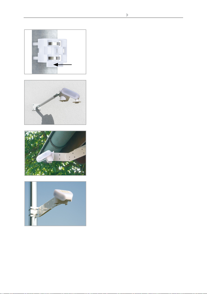
2.3. Mounting the sensor
2.3.1. Attaching the mount
The sensor comes with a combination wall/pole mount. The mount comes adhered by
adhesive strips to the rear side of the housing. Fasten the mount vertically onto the wall
or pole.
Fig. 3
The weather station must be mounted in the
horizontal transverse direction (horizontally).
Horizontal
Fig. 4
For installation in the northern hemisphere,
the weather station must be aligned to face
south.
For installation in the southern hemisphere,
the weather station must be aligned to face
north.
North
South
Fig. 5
When wall mounting: flat side on wall, crescent-
shaped collar upward.
Collar
6 Installation and commissioning
P03/3 Weather Station • Status: 09.06.2016 • Technical changes reserved. Errors reserved.
Fig. 6
When pole mounting: curved side on pole, collar
downward.
Collar
Fig. 7
Different mounting arms are available from Els-
ner Elektronik as additional, optional accessories
for flexible installation of the weather station on
a wall, pole or beam (pictures of sensors exem-
plary).
Example of the use of a mounting arm: Due to
flexible ball joints, the sensor can be brought
into ideal position.
Fig. 8
Example use of the hinge arm mounting:
With the hinge arm mounting, the weather sta-
tion projects from beneath the roof overhang.
Sun, wind and precipitation can act upon the
sensors without hindrance.
Fig. 9
Example use of the hinge arm mounting:
Fitting to a pole with worm drive hose clips

7 Installation and commissioning
P03/3 Weather Station • Status: 09.06.2016 • Technical changes reserved. Errors reserved.
2.3.2. View of rear side and drill hole plan
Langloch 7,5 x 5 mm
Fig. 10 a+b
Drill hole plan
Dimensions of rear side of
housing with bracket. Sub-
ject to change for technical
enhancement.

8 Installation and commissioning
P03/3 Weather Station • Status: 09.06.2016 • Technical changes reserved. Errors reserved.
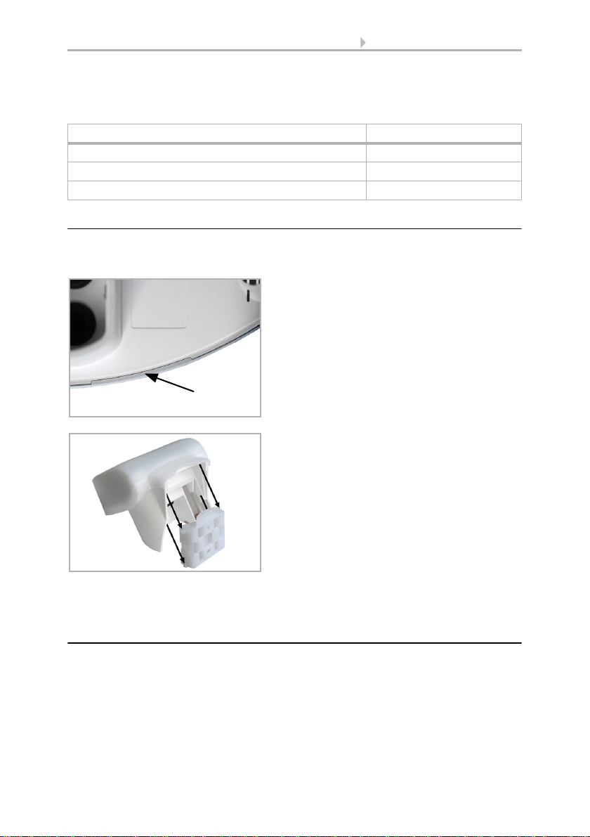
2.3.3. Preparing the sensor
The weather station cover with the rain sensor snaps in on the left and right along the
bottom edge (see figure). Remove the weather station cover. Proceed carefully, so as
not to pull off the wire connecting the PCB in the bottom part with the rain sensor
in the cover (wire with push-connector).
Push the connecting cable through the rubber seal on the bottom of the weather sta-
tion and connect the power and data cables to the terminals provided for this purpose.
The supply cable to the weather station should be a maximum of 30 m long. The con-
nection is by typical telephone cable (J-Y(ST)Y 2 × 2 × 0.8).
The connection cable must be plugged in between the cover and circuit board.
2.3.4. PCB Layout
Fig. 11
1 Lid with rain sensor
2 Cover Snaps
3 Bottom part of housing
2
3
1
Unsnap cover and
remove upwards
Abb. 12: Overview PCB
1 Socket for connecting
cables to
rain sensor in housing
cover
2 Connection plug
1: +24 V DC | 2: GND |
3: Data (massive cable
up to 0.8 mm²)
3 Control LED GPS recei-
ver
4Socketforjumper
1
2
3
4
a
b
9 Installation and commissioning
P03/3 Weather Station • Status: 09.06.2016 • Technical changes reserved. Errors reserved.
Set jumper:
Please reboot the system after the setting of the jumper!
2.3.5. Mounting the sensor
Close the housing by putting the cover back over the bottom part. The cover must snap
in on the left and right with a definite “click”.
To remove it, the sensor can be simply pulled upwards out of the mount, against the
resistance of the fastening.
2.4. Notes on mounting and commissioning
Do not open weather station if water (rain) might ingress: even some drops might
damage the electronic system.
Observe the correct connections. Incorrect connections may destroy the weather sta-
tion or connected electronic devices.
Please take care not to damage the temperature sensor (small blank at the bottom part
of the housing.) when mounting the weather station. Please also take care not to break
Control model Jumper position
WS1000 Touch no jumper
All other models up to production year 2001 jumper at position (a)
All other models from production year 2002 on jumper at position (b)
Fig. 13
Make sure the cover and bottom part are
properly snapped together! This picture is
looking at the closed sensor from under-
neath.
Fastening
Fig. 14
Push the housing from above into the fas-
tened mount. The bumps on the mount must
snap into the rails in the housing.
10 Installation and commissioning
P03/3 Weather Station • Status: 09.06.2016 • Technical changes reserved. Errors reserved.
away or bend the cable connection between the blank and the rain sensor when con-
necting the weather station.
Remove all existing protection labels after installation.
The correct wind value may only be supplied about 30 seconds after the supply voltage
has been connected.
2.5. Maintenance of the weather station
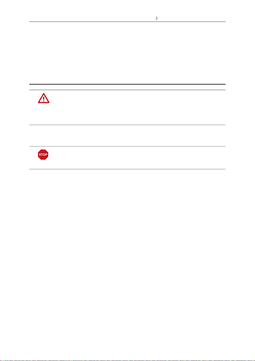
WARNING!
Risk of injury caused by components moved automatically!
The automatic control can start system components and place people in
danger.
• Always isolate the device from the mains for servicing and cleaning.
The device must regularly be checked for dirt twice a year and cleaned if necessary. In
case of severe dirt, the sensor may not work properly anymore.
ATTENTION
The device can be damaged if water penetrates the housing.
• Do not clean with high pressure cleaners or steam jets.
Table of contents
Other Elsner Weather Station manuals

Elsner
Elsner Suntracer KNX-GPS Guide

Elsner
Elsner Suntracer KNX basic Guide

Elsner
Elsner Suntracer KNX basic Guide

Elsner
Elsner Suntracer KNX sl Guide

Elsner
Elsner Suntracer KNX sl Guide

Elsner
Elsner Suntracer KNX basic Series User manual

Elsner
Elsner KNX Suntracer pro Guide

Elsner
Elsner Suntracer KNX-GPS User manual

Elsner
Elsner P03 3 User manual


