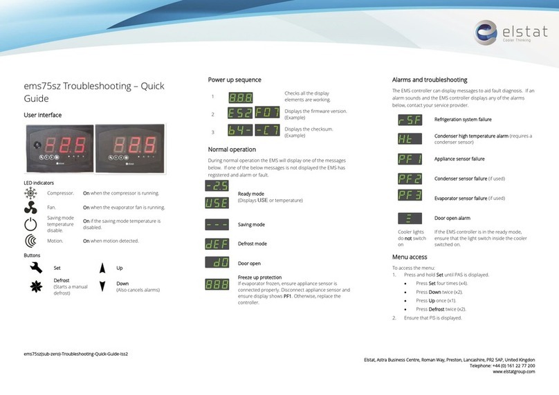
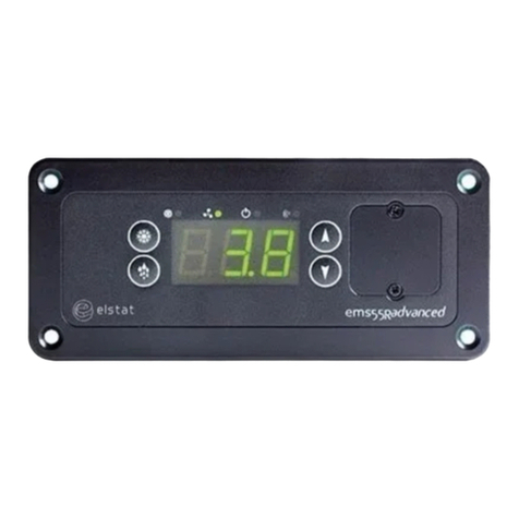
Elstat Nexo CMS200 User manual

CMS200
PRODUCT MANUAL Issue 6

Copyright © Elstat Ltd
2017 All Rights Reserved
All information in this document is property of
Elstat Ltd
Commercial use and distribution of the contents
of this publication is not allowed without express
and prior written consent of Elstat Ltd

CMS200 Product Manual, Issue 6
www.nexo.com Page 3
CONTENTS
1. CONTROLLER WITH INTELLIGENCE
1.1 Control Display Module 5
1.2 Power Supply Module 8
1.3 Relay ratings 12
1.4 Temperature input ranges 12
1.5 Environmental ratings 13
2. ACCESSORIES
2.1 Temperature sensors 15
2.2 Door switch 17
2.3 Motion sensor 19
3. USER GUIDE
3.1 Power-up sequence 21
3.2 Function buttons 21
3.3 SubZero Firmware menus 22
3.4 The menu arrangement 23
3.5 Menu access 24
3.6 Test routines 24
3.7 Viewing the last three cooler faults witnessed by the controller 32
3.8 Half reset 33
3.9 Viewing statistics 35
4. ALARMS AND TROUBLESHOOTING
4.1 ‘Limp home’ functionality 37
4.2 Door open alarms 37
4.3 Door alarms ‘Limp home’ mode 38
4.4 Temperature sensor alarms 39
4.5 Appliance sensor failure alarms 39
4.6 Refrigeration system failure alarms 40

CONTENTS
Product Manual, Issue 6 CMS200
www.nexo.comPage 4
5. COOLER AND CONTROLLER TROUBLESHOOTING TIPS
5.1 RSF Alarms 41
5.2 Door Switch Broken Alarms 41
5.3 Door Broken Alarms 41
5.4 Appliance Sensor Alarms 41
5.5 Condenser Sensor Alarms 42
5.6 Evaporator Sensor Alarms 42
5.7 Freeze-up protection (888) 42
5.8 Condenser high temperature (Ht) alarms 42
5.9 Other Problems 43
6. PARAMETER REFERENCE
6.1 Parameters by function 45
6.2 Parameter validation 46
6.3 Parameters denition 46
7. APPROVALS
7.1 Product Approvals 61
7.2 Bluetooth Approvals 62
8. GLOSSARY OF TERMS
8.1 Acronyms 63
8.2 Controller and accessory terms 63

CMS200 Product Manual, Issue 6
www.nexo.com Page 5
1. CONTROLLER WITH INTELLIGENCE
The Nexo controllers are the rst truly intelligent refrigeration
solution for the beverage industry that delivers consumer insights
from eld data to optimize and take complete control of cold drink
marketing.
Elstat’s game-changing Nexo platform is a powerful tool that
connects drink brands directly to consumers at the point of sale,
wherever they are in the world, to create sustainable and protable
relationships.
The energy management system controllers from Elstat are used
in a variety of drinks coolers, optimising energy savings, without
compromising on drinks serving temperature.
The CMS200 Nexo controller is designed for sub-zero beer coolers.
It consists of Control Display Module (CDM) and a Power Supply
Module (PSM) connected by an interface cable.
1.1 Control Display Module
The control display module (CDM) consists of the user interface
with a large 3-digit 7-segment LED display, the temperature
sensors and door switch inputs.
CDM is powered by a 12VDC supply from the power supply
module and it provides the following functionality:
Feature Description
User and
diagnostic
information
3-digit, 7-segment display that displays the product temperature and other information
such as defrost and alarm conditions.
Push buttons enable the end-users to cancel alarms and service technicians to run test
routines.
Product
temperature
An appliance sensor measures temperature of the refrigeration compartment. The
controllers use the refrigeration temperature to manage the product temperature.
Refrigeration
system high
temperature alarm
An optional condenser sensor measures the temperature of the refrigeration system.
The controllers use the temperature to alert to problems such as blocked condensers.
Motion detection A remote or integrated motion sensor enables controllers to detect activity when
someone moves in front of the cooler.
Door open
detection
A door switch enables the controllers to detect cooler activity when someone opens the
cooler doors.
Boosted defrost Timed-based or temperature-based defrost can be boosted by a defrost heater or a hot
gas defrost. An evaporator sensor is required for temperature-based defrost.

Product Manual, Issue 6 CMS200
www.nexo.comPage 6
The control display module is available with either an integrated or a remote motion sensor. Both CDM
variants are made from food grade plastics and are safe for internal installation.
Controller with integrated motion detection
(IMD)
Controller with remote motion detection
(RMD)
1
9
11
10
23 4 5678
This variant should always be installed where the
sensor can ‘see’ activity. It is recommended that the
CDM is installed externally on the cooler.
This variant of the CDM can be installed internally
on the cooler but the remote motion sensor must
be installed where it can ‘see’ activity.
Item LED Indicator Function
1Compressor On when the compressor is running.
2Evaporator fan On when evaporator fan is running.
3
Saving
temperature
disable
On if the saving mode temperature is disabled.
The controller maintains the Ready mode temperature at all times.
4Motion On when motion is detected.
Item Push
Button Name Function
5Set Accept/forward - selects menu options and parameters.
6Down Scrolls down menus. Decreases parameter values. Cancels the rSF,
d0 and Ht alarms.
7Up Scrolls up menus. Increases parameter values.
8Defrost
Return/backward - De-selects menu options and parameters.
Activates a manual defrost (only applicable if controller is set to
timed defrost and temp is below termination temp).
9 Logo Elstat logo
10 LED Display 3-digit 7-segment LED display
11 Sensor Motion sensor

CMS200 Product Manual, Issue 6
www.nexo.com Page 7
1.1.1 CDM Overall dimensions
The overall dimensions of the CDM are shown in the following diagram:
140 mm 30 mm
100 mm
111 mm
50 mm
1.1.2 CDM Mounting
The control display module is designed for panel mounting and is secured using the tted clips.
The aperture dimensions are as shown.
To mount the control display module simply
push in the unit into the aperture till it clicks into
place.
Check that the control display module is held rmly in position.
72 mm
122 mm
72 mm
122 mm

Product Manual, Issue 6 CMS200
www.nexo.comPage 8
1.1.3 CDM Electrical connections
1Modem interface
2 3 4 56 7 9
18
2RMD port (If applicable)
3Interface cable
4Evaporator sensor
5Door sensor
6Condenser sensor
7Appliance sensor
8Stock sensor
9RJ45 Port
1.2 Power Supply Module
The power supply module (PSM) contains
the power supply for the control unit and
the relays to switch the following cooler
components:
Feature Description
Compressor relay Switches the compressor to manage the temperature of the refrigeration
compartment.
Evaporator fan relay Switches the evaporator fan to minimize heat transfer to products when the
compressor is not running.
Auxiliary relay Switches a defrost heater or a solenoid valve for hot gas defrosts.
Lights relay Switches the cooler lights.

CMS200 Product Manual, Issue 6
www.nexo.com Page 9
1.2.1 PSM Overall dimensions
The overall dimensions of the PSM are shown in the following diagram:
134 mm
121 mm
62 mm
117 mm
46 mm
1.2.2 PSM Mounting
The power supply module is tted with the following cables:
`High voltage cable terminated with 6-way connector for connecting
to the compressor, lights, evaporator fan, and defrost heaters or
valves.
`Interface cable that connects to the control display module.
The power supply module must be mounted vertically with the cables
exiting vertically downwards.
The power supply module has an (Ingress Protection) IP rating of IPX5,
which means the power supply module is protected against water jets.
Note
The power supply module must be located in a non-
refrigerated area of the cooler and it must not be placed
in the hot exhaust ow of the condenser.

Product Manual, Issue 6 CMS200
www.nexo.comPage 10
The power supply module must be xed using screws with the following characteristics:
`Head
maximum diameter 7.8mm (0.31in) and minimum diameter 6.2mm (0.24in)
`Thread
maximum diameter 4.8mm (0.19in).
The screws must be tightened to a maximum torque of 0.5Nm (0.37lbt).
Note
Using rivets to mount the power supply module invalidates the warranty.
Cable routing to the PSM is critical as water can trace or follow
the cable downwards.
Therefore, immediately prior to the connection to the power
supply module, a drip-loop must be formed in all wiring.
Cable routing looms must not be secured to hot pipes or
vibrating components.
Secure cable routing looms with clips where ever possible.
1 - High voltage connection cable (six way)
2 - Interface cable PSM & CDM
3 - Drip loop
Note
The Water Ingress Protection ratings (IP ratings) are only valid when the product is
mounted in the recommended orientation shown below.
Failure to follow these guidelines will invalidate the designed levels of Ingress Protection
and any subsequent damage incurred will not be covered under the warranty terms.
The dimensions of the xing holes for mounting the PSM:
64.5 mm
121 mm 4.5 mm4 x
Example of the Power Supply Module mounted.

CMS200 Product Manual, Issue 6
www.nexo.com Page 11
1.2.3 PSM Electrical connections
Pin Description Colour Connectors
1 Live Brown
2 Evaporator fan Yellow
3 Defrost heater Pink
4 Neutral Blue
5 Lights White
6 Compressor Red
1.2.4 Wiring diagram
A - Interface cable H - Control display module Q - Door switch
B - Lights I - RMD R - Motion sensor
C - Evaporator fan J - Evaporator sensor S - Display
D - Defrost heater K - Condenser sensor T - RJ45 Port
E - Compressor L - Live V - Modem interface
F - Power supply module N - Neutral W - Stock / product sensor
G - 6-Way connector P - Appliance sensor

Product Manual, Issue 6 CMS200
www.nexo.comPage 12
1.3 Relay ratings
Relay Maximum IEC rating @ 100 – 240VAC Maximum UL ratings @ 120V
Compressor 10(10)A, p.f. 0.6 10FLA, 60LRA
Lights 4(4)A, p.f. 0.6 250W Ballast
Evaporator fan 6(6)A, p.f. 0.6 6FLA, 36LRA
Auxiliary 6(6)A, p.f. 0.6 6FLA, 36LRA
Note
The auxiliary relay is normally used to switch a defrost heater, or a solenoid valve, for hot
gas defrosts.
Note
This controller is designed for integration into 3rd party equipment only and should
be installed according to these instructions and all relevant local electrical and safety
standards.
1.4 Temperature input ranges
Sensor Input range (ºC) Input range (ºF)
Appliance sensor -15ºC to 50.0ºC +/- 0.5ºC 5ºF to 122ºF +/- 1ºF
Condenser sensor 50ºC to 125ºC +/- 5.0ºC 122ºF to 257ºF +/- 10ºF
Evaporator sensor -15ºC to 50ºC +/- 0.5ºC 5ºF to 122ºF +/- 1ºF
Note
The NTC thermistor from Elstat is rated at -35ºC to 125ºC (-31ºF to 257ºF).

CMS200 Product Manual, Issue 6
www.nexo.com Page 13
1.5 Environmental ratings
Characteristic Power supply module Control display module
IP Rating IPX5 IP65 Front Facia, IP24 All Over
Maximum operating temperature Sub Zero PSM: 55°C (131ºF) 55ºC (131ºF)
Minimum operating temperature 0ºC (32ºF) -10ºC (14ºF)
Housing material Black polycarbonate, Food grade
(non-contact)
Black polycarbonate, Food grade
(non-contact)
Operating control Electronic Thermostat Electronic Thermostat
Construction
Incorporated Class II control
for use in Class I or Class II
appliances
Class II (SELV electronic control)
Software Class Class A Class A
Limitation of operating control Continuous Continuous
Action Type 1B Type 1B
Control pollution degree Degree 2 Degree 2
Rated impulse voltage Loads 2.5KV
Control 330V (SELV*)
Loads 2.5KV
Control 330V (SELV*)
Temperature ball pressure test 160ºC (PCB)
125ºC (Enclosure)
160ºC (PCB)
125ºC (Enclosure)
75ºC (front face)
*All SELV circuits (signal and data connectors) separated from mains by reinforced insulation
Before beginning installation, remove all protective lm from between the seals of the CDM (control display
module). The seals are malleable, to ensure a water resistant seal around cables and prevent water ingress.

Product Manual, Issue 6 CMS200
www.nexo.comPage 14

CMS200 Product Manual, Issue 6
www.nexo.com Page 15
2. ACCESSORIES
2.1 Temperature sensors
Temperature sensors are available from Elstat with various cable lengths. To help identify sensor cables
during the installation, Elstat can supply sensor cables with blue identication sleeves. For example,
if the appliance sensor cable is plain black; the condenser sensor cable can be purchased with a blue
identication sleeve.
The sensor circuit is designed for safety extra low voltage (SELV). Therefore, if the sensor cable needs to be
joined during production or maintenance, only connectors normally used in SELV circuits can be used.
Note
Connectors designed to carry mains voltages must not be used to join cables to the
sensor circuit.
The temperature sensors have a negative temperature coecient (NTC). Each make and type of sensor has
a specic resistance versus temperature curve. Therefore, only sensors supplied by Elstat should be used.
The NTC thermistor is rated from -35ºC to 125ºC (-31ºF to 257ºF).
2.1.1 Appliance sensor
The appliance sensor measures air temperature
of the refrigerated compartment by measuring
the return air temperature.
The diagram shows the
recommended position of
the appliance sensor.
The appliance sensor
measures the air
temperature after the
air has been drawn over
the products. The return
air provides a close
approximation of the
product temperature.
To measure the return air
temperature, secure the sensor to allow air to ow over the sensor head.
The sensor head should be placed at a right-angle to the air ow and secured using a
P-clip. The sensor head should not be completely covered by the P-clip or the sensor
will not function correctly.
Note
The sensor head is fragile and can easily be damaged. Do not use cable ties to secure
the sensor head or sensor cable as this invalidates the warranty.
To help place the appliance sensor, the parameter calibration 1 (CA1) denes an oset temperature. For
more information refer to Parameters section.

Product Manual, Issue 6 CMS200
www.nexo.comPage 16
2.1.2 Condenser sensor
This sensor measures the temperature of the refrigeration system. Excessive condenser temperature is
usually due to poor preventative maintenance, such as poorly cleaned condenser, or condenser fan failure.
The controllers can generate alarms if the refrigeration system temperature rises too high.
Note
Condenser sensor needs to be mounted on the liquid pipe of the condenser.
The value of the high
temperature is set
by measuring the
refrigeration system
temperature, when
the condenser is
approximately 75%
blocked.
The temperature is then set as the value of the condenser high temperature
(Ht) parameter. Ensure that the condenser sensor is xed using a metal pipe
clip (1) or foil tape (2) as shown.
Elstat can supply pipe clips for 6-8 mm and 8-10 mm pipes.
A
B
C
D
E
A - Condenser hot gas pipe (Condenser inlet pipe)
B - Condenser
C - Compressor
D - Liquid pipe (Condenser outlet pipe)
E - HT Sensor (Dual temperature sensor)
Caution
Do not use cable ties. The head of the sensor is fragile and can be easily damaged. Using
cable ties to secure the sensor head or sensor cable invalidates the warranty.
Do not attach sensor cables to hot pipes or allow the sensor cables to come into contact
with hot pipes.

CMS200 Product Manual, Issue 6
www.nexo.com Page 17
2.1.3 Evaporator sensor
The evaporator sensor measures the temperature of the evaporator. CMS200 controllers can use the
temperature of the evaporator to activate and terminate defrost cycles.
The evaporator sensor should be placed in the
immediate proximity of the evaporator.
Mount the sensor head inside the evaporator cooling
ns, as shown. The sensor head must be mounted
securely to prevent being dislodged due to vibration.
For coolers tted with a defrost heater, the evaporator
sensor should be placed as far away as possible from
the heating element, for example at the opposite end of
the evaporator.
If the evaporator sensor measures the localized heating
from the heating element, defrost cycles will terminate
before the whole evaporator has had the opportunity to
defrost.
Note
Do not use cable ties. The head of the sensor is fragile and can be easily damaged. Using
cable ties to secure the sensor head, or sensor cable, invalidates the warranty.
2.2 Door switch
Door switches are used to detect door openings. They are SELV (safety extra low voltage) components that
are able to create an open and closed circuit. The Elstat enhanced door switch, and activator, are over-
moulded for increased physical protection and resistance to water ingress.
Door switch cables are available with various cable lengths.
Door switches must be used with
the corresponding activator.
Door switches are usually mounted with the door switch on the cooler and the activator on the door. Both
components must be xed using counter sunk screws or bolts with the following characteristics:
`Head: countersunk, maximum diameter 5.0mm (0.24in)
Thread: maximum diameter 3.0mm (0.16in)
`The screws must be tightened to a maximum torque of 0.5Nm (0.37lb ft)
Note
If using non-Elstat door switches, ensure that they are double insulated.

Product Manual, Issue 6 CMS200
www.nexo.comPage 18
Overall dimensions for the door switches are as shown.
60 mm
15 mm
7 mm
40 mm
L
Note
Door switches and activators supplied by Elstat must not be installed using rivets.
Using rivets invalidates the warranty.
The alignment of the door switch and activator is critical for the correct operation of the door switch. The
table details alignment tolerances.
Alignment Dimensions Notes
X Horizontal 0mm (0in)
+/- 20mm (0.7in)
Measured when the door is closed and the gap
(z-dimension) is correct.
Y Vertical 0mm (0in)
+/- 10mm (0.4in)
Measured when the door is closed and the gap
(z-dimension) is correct.
Z Gap 0mm (0in) to 5mm (0.2in)
+/- 2mm (0.07in)
The diagram below shows the horizontal, vertical, and gap alignment between the door switch and the
activator for open and closed doors.
Z
X Y
To mount door switches on double-door coolers, two door switches must be connected in series. Connect
two door switches in series as follows:
`Remove the two wires from one of the connectors. Be careful not to damage the terminals.
`Remove the white wire from the second connector. Again, be careful not to damage the
terminal.

CMS200 Product Manual, Issue 6
www.nexo.com Page 19
`Insert the white wire of the rst cable into the connector of the second cable ensuring that the
terminal is in the correct orientation.
`Connect the red wire from the rst cable and the white wire from the second cable together
using a butt splice or similar.
The image below shows two door switches connected in series.
A - Door switch cables
B - Cable connector
C - Molex connector
2.3 Motion sensor
Motion sensors are passive infra-red (PIR) devices
that detect activity. The diagram shows the
detection pattern of motion sensors.
The motion sensor must have an uninterrupted
view directly in front and to the sides.
The preferred location of the motion sensor is in
the upper section or in header panel of the cooler
to ensure the best motion detection and to lower
the risk of the motion sensor being blocked by
objects such as packages.
For the controllers without integrated motion
sensor, a remote motion sensor can be used.
The remote motion sensor head is supplied
detached from the cable to allow the cable to be
easily routed through holes or foamed into place
as required by the OEM or installer.
The motion sensor should be mounted vertically
with the connector at the bottom for optimal
performance. Mounting horizontally with the
connector at the side results in the motion sensor
being less sensitive. However, the motion sensor
still works correctly. The motion sensor must not
be located behind any material such as glass or
polycarbonate.
Note
Using rivets invalidates the warranty.
2.5m
3m

Product Manual, Issue 6 CMS200
www.nexo.comPage 20
For a motion sensor that is not mounted ush with the panel, the diagram shows the minimum
recommended clearances to ensure motion detection. For example, if the motion sensor is mounted
15mm behind the panel, a 30mm diameter aperture is required.
55 mm 30 mm65 mm
15 mm
The motion sensor head must be xed using counter sunk screws or bolts with the following characteristics:
`Head: countersunk, maximum diameter 6.0mm (0.24in)
`Thread: maximum diameter 4.0mm (0.16in).
The screws must be tightened to a maximum torque of 0.5Nm (0.37lbt).
Overall dimensions of the motion sensor Dimensions of the mounting holes
25 mm
41 mm
5.435 mm
48.5 mm
8 mm
36 mm
14.2 mm
20.5 mm 20.5 mm
10.2 mm
12.2 mm
Sample of a mounted motion sensor
Table of contents
Other Elstat Controllers manuals
Popular Controllers manuals by other brands
Emerson
Emerson Dixell XR10C Installating and operating instructions
ARRI
ARRI CLAYPAKY BUDDYLIGHT CA1010 instruction manual
AERMEC
AERMEC CC2 User & installation manual
Carrier
Carrier MPC Open XP Series Installation and startup guide
Pixsys
Pixsys ATR 621 series user manual
Tyco Security Products
Tyco Security Products DSC Neo Power Series manual
