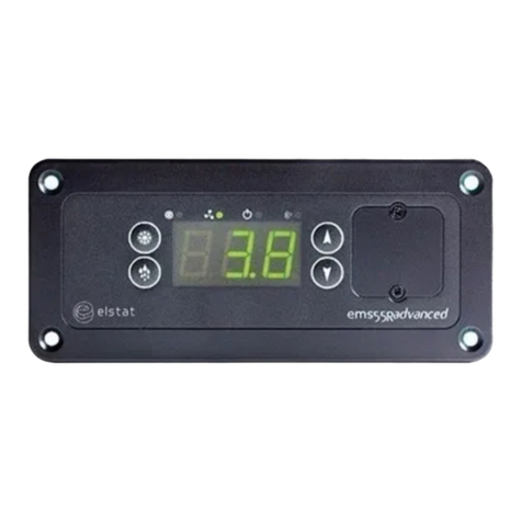
Elstat ems75sz User manual

ems75sz (Sub-Zero)
Firmware: U09 n05
27 February 2014
www.elstatgroup.com

Table of contents
1 EMS controller reference guide 4
1.1 About this reference guide 4
2 Water ingress – advisory information for FMEA analysis 5
3 What is an ems75sz (sub-zero)? 6
3.1 Control Display Module (CDM) 6
3.2 Power Supply Module (PSM) 7
3.3 ems75sz user interface 7
3.3.1 Push buttons: 8
3.3.2 LED indicators: 8
3.4 ems75sz relay ratings 8
3.5 Temperature input ranges 9
3.6 ems75sz wiring diagram 9
3.7 Power supply module 10
3.8 Power supply module – electrical connections 11
3.9 How to mount the power supply module 11
3.9.1 Power supply module dimensions 12
3.10 Control display module 13
3.11 How to mount the control display module 15
3.12 External control display module – electrical connections 16
3.13 Internal control display module – electrical connections 17
3.14 Environmental ratings 17
4 User guide 18
4.1 Power-up sequence 18
4.2 Function buttons - ems sub zero 18
4.3 Indicators 19
4.4 Display codes 19
4.5 What are the menus? 20
4.6 How to access the menu EMS controllers 21
4.7 How to view the ems75sz parameter settings (PS) 21
4.8 How to run the test routine (tst) 23
4.8.1 The relay test 24
4.8.2 The heater relay test 25
4.8.3 The analogue input test 26
4.8.4 The motion sensor test 26
4.9 How to view the last three alarms (FLt) 27
4.10 Passwords 28
4.11 How to perform a half reset (Hr) 29
1 of 86
27 February 2014

4.12 Statistics 30
4.13 How to view statistics 30
5 EMS controllers functionality 32
5.1 Defrost - Glass Door Cooler (GDC firmware) 32
5.2 Evaporator fan management 33
5.3 Lights management 34
5.4 Alarms 34
5.5 Compressor management 34
5.6 Product temperature 35
6 How EMS controllers work - self-learning 37
6.1 How EMS controllers work - example 38
6.2 Self-learning 38
6.3 What is the self-learning matrix? 40
6.4 Activity 40
6.5 Activity frequency 41
6.6 How a 1-day learning period works 41
6.7 How a 7-day learning period works 43
6.8 Saving mode 45
6.9 How EMS controllers switch between the ready and saving mode 46
6.10 Ready mode 47
6.11 How the self-learning matrix updates after the learning period 48
7 What are the accessories? 49
7.1 Temperature sensors 49
7.2 Temperature sensor - where used 49
7.3 How to mount the appliance sensor 50
7.4 How to mount the condenser sensor 51
7.4.1 Condenser sensor 51
7.5 How to mount the evaporator sensor 51
7.6 Door switch 52
7.7 How to mount the door switch 52
7.8 How to mount door switches on double-door coolers 53
7.9 Motion sensor - ems75sz 54
7.10 Motion sensor 55
7.11 How to mount a remote motion sensor 55
8 How to troubleshoot ems75sz 57
8.1 Troubleshooting 57
8.2 How to check that EMS controllers are working correctly 57
8.3 How to troubleshoot condenser high temperature (Ht) alarms 58
8.4 Door open alarm - display 58
8.5 How to troubleshoot door alarms (door switch fitted) 59
8.6 How to troubleshoot door alarms (no door switch fitted) 59
8.7 How to troubleshoot problems with freeze-up protection (888) 60
8.8 How to troubleshoot motion sensor alarms 61
8.9 How to troubleshoot not cooling problems 61
8.10 How to troubleshoot refrigeration system failure (rSF)alarms 62
8.11 Sensor failure 62
8.12 How to troubleshoot temperature sensor alarms 63
9 Parameter reference 65
9.1 Parameter by owners 65
9.2 Controller parameters 65
9.2.1 Firmware variants 66
9.2.2 ems25 series and GDCfirmware defrost parameter exceptions 66
2 of 86
27 February 2014

9.2.3 New or revised parameters 66
9.3 Temperature setting rules 66
9.4 Celsius or Fahrenheit (CF) 67
9.5 Set point (SPC or SPF) 67
9.6 Differential (dIF) 67
9.7 Calibration 1 (CA1) 68
9.8 Calibration 2 (CA2) 68
9.9 Saving set point (SSP) 68
9.10 Saving differential (Sd) 69
9.11 Freeze-up protection (dtt) 69
9.12 Fan set point (FSP) 69
9.13 Condenser high temperature (Ht) 70
9.14 Defrost activation temperature (ddt) 70
9.15 Defrost termination temperature (dtd) 71
9.16 Compressor rest time (rt) 71
9.17 Delay to saving (dS) 72
9.18 Lights delay (Ld) 72
9.19 Saving restart period (Sr) 72
9.20 Refrigeration system failure (Ct) 72
9.21 Defrost interval (dE) 73
9.22 Defrost duration (dd) 73
9.23 Defrost method (dF) 73
9.24 Defrost termination method (dtF) 74
9.25 Fan cycle on (FCO) 74
9.26 Fan cycle off (FCF) 74
9.27 Display stability (d2) 75
9.28 Buzzer enable (b0) 75
9.29 Buzzer duration (b1) 76
9.30 Alarm delay (Ad) 76
9.31 Activity frequency (AF) 76
9.32 Motion sensor enable (Sn) 77
9.33 Saving temperature disable (PEr) 77
9.34 Learning period (LP) 77
9.35 Display (dIS) 78
9.36 Marketing mode (Ar) 78
9.37 Defrost heater (dHr) 78
10 What variations of the ems75sz (sub zero) can I order? 80
10.1 Examples of CDM colours 81
11 Technical data ems75sz 82
11.1 Dimensional drawings: 82
11.2 Controller relays: 82
11.3 Temperature sensors: 82
11.4 Environmental ratings: 83
11.5 Product approvals: 83
12 Glossary of terms 84
12.1 Acronyms 84
12.2 Controller and accessory terms 84
3 of 86
27 February 2014

1 EMS controller reference guide
EMS (energy management system) controllers from Elstat are used in a variety of drinks coolers,
optimising energy savings, without compromising on drinks serving temperature.
A range of controllers are available to suit applications such as:
lSingle door coolers
lDouble door coolers
lOpen front coolers
lVending machines
lSub-zero beer coolers
1.1 About this reference guide
The purpose of this guide is to explain in detail all information regarding Elstat controllers including
the user interface, parameters, accessories and troubleshooting.
Complimentary information is also available from Elstat such as accessory lists, accessory data
sheets and single sheet user guides.
4 of 86
27 February 2014

2 Water ingress – advisory information for FMEA analysis
Elstat products have been designed to minimise any risks associated with water ingress and all con-
trollers are IPX5 certified.
The OEM or installer is responsible to ensure that local/country laws and regulatory requirements
are met.
5 of 86
27 February 2014

3 What is an ems75sz (sub-zero)?
The ems75sz is designed for sub-zero beer coolers. The ems75sz consists of power supply module
and a control display module connected by an interface cable. Example shown below.
3.1 Control Display Module (CDM)
The control display module is powered by a 12VDC supply from the power supply module. The con-
trol display module provides the following functionality.
Feature Description
User interface
3-digit, 7-segment display that displays the product temperature and other information such
as defrost and alarm conditions. Enables end-users to cancel alarms and service technicians
to run test routines, view parameter settings, and so on.
Self-learning Integrated motion sensor detects activity when someone moves in front of the cooler.
An optional door switch can detect cooler activity when someone opens the cooler doors.
Serving
temperature
Appliance sensor measures the air temperature of the refrigeration compartment.
Self-learning determines when the product should be at the ready mode temperature (the
optional serving temperature) or the saving mode temperature.
Refrigeration alarms Refrigeration system alarms can alert to possible cooling problems and an optional condenser
sensor can alert to problems such as blocked condensers.
Boosted defrost Timed-based or temperature-based defrost can be boosted by a defrost heater or a hot gas
defrost. An evaporator sensor is required for temperature-based defrost.
The control display module is available with either an integrated or a remote motion sensor. Addi-
tionally Elstat can supply and rectangular or curved CDM shape. All CDM variants are made from food
grade plastics.
The integrated motion sensor varient should always be installed where it can 'see' activity and it is
recommended that the CDM is installed externally on the cooler. An example of a CDMwith integ-
rated motion sensor:
6 of 86
27 February 2014

The remote motion sensor varient of the CDM can be installed internally on the cooler. The remote
motion sensor must be installed where it can 'see' activity. An example of a CDMwith remote motion
sensor:
See "How to mount a remote motion sensor" on page 55
3.2 Power Supply Module (PSM)
The power supply module contains the power supply for the control unit and the relays to switch the
following cooler components:
Feature Description
Compressor relay Switches the compressor to manage the temperature of the refrigeration com-
partment.
Evaporator fan relay Switches the evaporator fan to minimize heat transfer to products when the com-
pressor is not running.
Auxiliary relay Switches a defrost heater to a solenoid valve for hot gas defrosts.
Lights relay Switches the cooler lights.
3.3 ems75sz user interface
The user interface of the ems75sz is as follows:
7 of 86
27 February 2014

3.3.1 Push buttons:
Button Name Function
Defrost Starts a defrost cycle.
Set Selects menu options and scrolls through the parameters.
Up Increases the parameter values.
Down Scrolls down menus, decreases parameter values, and cancels
alarms.
3.3.2 LED indicators:
Indicator Function Colour
Compressor On when the compressor is running Green
Evaporator fan On when evaporator fan is running. Red
Saving
temperature
disable
On if the saving mode temperature is disabled.
The controller maintains ready mode temperature at all times. Red
Motion On when motion is detected. Red
3.4 ems75sz relay ratings
The table below details the relay ratings of the ems75sz:
8 of 86
27 February 2014

Relay Maximum IEC rating @100-
240VAC Maximum UL rating @ 120VAC
Compressor 10(10)A, p.f. 0.6
not applicable
Lights 4(4)A, p.f. 0.6
Evaporator fan 6(6)A, p.f. 0.6
Auxiliary 6(6)A, p.f. 0.6
Note:
lThe auxiliary relay is normally used to switch a defrost heater, or a solenoid valve, for hot gas defrosts.
3.5 Temperature input ranges
The table below shows the temperature input ranges of the EMSsub zero controllers for each
sensor type:
Sensor Input range (ºC) Input range (ºF)
Appliance sensor -10ºC to 23.3ºC +/- 0.5ºC 14ºF to 74ºF +/- 1ºF
Condenser sensor 50ºC to 125ºC +/- 5.0ºC 122ºF to 257ºF +/- 10ºF
Evaporator sensor -30ºC to 15ºC +/- 0.5ºC -22ºF to 59ºF +/- 1ºF
Note:
lThe NTC thermistor from Elstat is rated at -35ºC to 125ºC (-31ºF to 257ºF).
3.6 ems75sz wiring diagram
Wiring diagram for the ems75sz:
9 of 86
27 February 2014

3.7 Power supply module
The power supply module (PSM), as shown below, contains the power supply and relays for con-
trolling the compressor, lights, evaporator fan, and an auxiliary relay that can be used for boosted
defrosts. The power supply module is fitted with the following cables:
lHigh voltage cable terminated with 6-way connector for connecting to the compressor, lights, evaporator fan,
and defrost heaters or valves.
lInterface cable that connects to interface cable of the control display module.
The power supply module must be mounted vertically with the cables exiting vertically downwards.
The power supply module has an (Ingress Protection) IP rating of IPX5, which means the power supply
module is protected against water jets.
Caution:
lThe power supply module must be located in a non-refrigerated area of the cooler. The power supply module
must not be:
lPlaced in the hot exhaust flow of the condenser
lExposed to temperatures greater than 50°C (122°F) or lower than 0°C (32°F).
The dimensions of the power supply module and the fixing holes are shown in the following diagram:
10 of 86
27 February 2014

3.8 Power supply module – electrical connections
The electrical connections of the high voltage connector are as follows:
Pin Description Connector
1 Live
2 Evaporator fan
3 Defrost heater
4 Neutral
5 Lights
6 Compressor
3.9 How to mount the power supply module
The power supply module must be fixed using screws with the following characteristics:
lHead: maximum diameter 7.8mm (0.31in) and minimum diameter 6.2mm (0.24in)
lThread: maximum diameter 4.8mm (0.19in).
The screws must be tightened to a maximum torque of 0.5Nm (0.37lbfft).
Caution:
lUsing rivets to mount the power supply module invalidates the warranty.
Cable routing to the EMS controller is critical as water can trace or follow the cable downwards.
Therefore, immediately prior to the connection to the power supply module, a drip-loop must be
formed in all wiring.
11 of 86
27 February 2014

Attention:
lCable routing looms must not be secured to hot pipes or vibrating components.
Secure cable routing looms with clips where ever possible.
3.9.1 Power supply module dimensions
The dimensions of the fixing holes are shown below.
The following is an example of the Power Supply Module mounted, but not connected:
12 of 86
27 February 2014

3.10 Control display module
The control display module, as shown in the following diagram, consists of the user interface, with a
large 3-digit 7-segment LED display, and the temperature sensors and door switch inputs.
lThe external variant of the control display module is designed to be mounted on the cooler with the display
visible to outlet customers and includes an integrated motion sensor. For example, mount in the header panel
of the cooler.
lThe internal variant is designed to be mounted within the cooler cabinet and does not have an integrated
motion sensor. For example, mount into an internal header panel.
The ems75sz controller display module is available in two styles as illustrated in the following dimen-
sional diagrams:
13 of 86
27 February 2014

lems75sz (controller display modules) CDMs are made from food grade materials and safe for internal
installation.
lThe control display module has an IP rating of IPX5 - protection against water jets.
Caution:
14 of 86
27 February 2014

lThe control display module must not be exposed to temperatures greater than 50°C (122°F)or lower than 0°C
(32°F).
3.11 How to mount the control display module
The control display module is designed for panel mounting and is secured using the fitted clips.
The aperture dimensions are shown below.
To mount the control display module, remove the retaining clip and insert the control display module
into the aperture, as shown below.
Then, place the retaining clip into position as shown below.
Finally, secure the retaining clip as shown below and ensure that the control display module is held
firmly in position.
15 of 86
27 February 2014

The image below shows the control display module fitted correctly into a header panel as seen from
the front of the cooler.
3.12 External control display module – electrical connections
The electrical connections of the external variant control display module as follows:
Label Description Connectors
1Interface cable -
to power supply module
2Parameter
programming port
3 aux Evaporator sensor
4 door Door switch
5 ht Condenser sensor
6 app Appliance sensor
16 of 86
27 February 2014

3.13 Internal control display module – electrical connections
The electrical connections of the external variant control display module as follows:
Label Description Connectors
1Interface cable -
to power supply module
2Parameter
programming port
3 Remote motion sensor
4 aux Evaporator sensor
5 door Door switch
6 ht Condenser sensor
7 app Appliance sensor
Note:
lThe remote motion sensor has a micro connector.
3.14 Environmental ratings
The table below details the general characteristics of the ems75sz:
Characteristic Power supply module Control display module
IP rating IPX5 IPX4
Maximum operating tem-
perature 55ºC (131ºF) 55ºC (131ºF)
Minimum operating temperature 0ºC (32ºF) 0ºC (32ºF)
Housing material Black polycarbonate Black polycarbonate
Before beginning installation, remove all protective film from between the seals of the CDM (control
display module). The seals are malleable, to ensure a water resistant seal around cables and prevent
water ingress.
17 of 86
27 February 2014

4 User guide
The user guide describes the power-up sequence and how to view parameters and statistics.
The user guide also describes how to:
lPerform a half-reset - to clear the self learning matrix only
lRun the test routine - for all relays and inputs
4.1 Power-up sequence
At the power up, the EMS controller displays the power-up sequence as follows:
18.8.8. to confirm that all segments of the display are functioning correctly
2Platform type and firmware version.
(example)
3Checksum of the parameter set.
(example)
The display then shows the appropriate display code. For example, the temperature or the word
USE.
4.2 Function buttons - ems sub zero
The EMS controller buttons access the EMS controller menus to view parameter values, reset the
EMS controller, and to run test routines. The EMS controller buttons perform the following functions:
Button Name Function - end user Function - service engineer
Defrost Starts a defrost cycle. Use as part of the controller password.
Set
Use as part of the controller password.
Selects menu options.
Scrolls through the parameters.
Up Use as part of the controller password.
Increases the parameter values.
Down Cancels alarms.
Use as part of the controller password.
Scrolls down menus.
Decreases parameter values
18 of 86
27 February 2014

4.3 Indicators
The EMS controller LED indicators are as follows:
Indicator Function Colour
Compressor On when the compressor is running. Green
Fan On when the evaporator fan is running. Green
Saving temperature
disable
On if the saving temperature is disabled.
The EMS controller maintains the ready mode temperature at all
times.
Red
Motion
On when motion sensor detects motion.
If the motion sensor is flashing continuously, the motion sensor may
be faulty.
Red
4.4 Display codes
The table below details the display codes for EMS controllers.
Display State Description
Ready mode
EMS controllers display the appliance sensor (cooler cabinet) tem-
perature, or the word USE
Also, the cooler lights are switched on.
See "How to check that EMS controllers are working correctly" on
page 57
Saving mode
EMS controllers keep products at the saving mode
temperature unless the saving temperature is disabled.
The saving temperature LED shows whether the saving mode tem-
perature is disabled.
The cooler lights are off unless the light delay (L d) parameter
keeps the lights on for a short period after the EMS controller
switches to the saving mode.
The marketing mode (Ar) keeps the lights on for the duration of
the saving mode.
Defrost mode
EMS controllers switch off the compressor and switch on the fan, if
applicable.
The compressor LED should be off and the evaporator fan LED
should be on.
Door open EMS controllers display d0 to show that the cooler door is open.
Alarm:
Door open
EMS controllers sound an alarm buzzer if cooler door remain open
for alarm delay (Ad) duration.
If the cooler door is still open after the time defined by the buzzer
19 of 86
27 February 2014
Other manuals for ems75sz
1
This manual suits for next models
1
Table of contents
Other Elstat Controllers manuals
