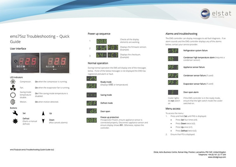
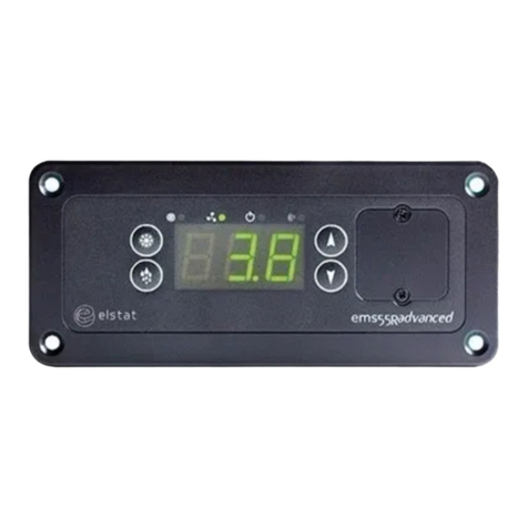
Elstat ems55advanced User manual

ems55advanced and
ems55Radvanced
18 February 2014
Firmware:U01 - n01 - ems55advanced and ems55Radvanced - GDC
Firmware: U02 - r01 - ems55advanced and ems55Radvanced - OFC
Elstat Electronics Ltd.
Astra Business Centre, Roman Way, Preston, Lancashire, PR2 5AP
+44 (0)161 2277200
www.elstatgroup.com

table of contents
1 ems controller reference guide 6
1.1 about this reference guide 6
2 what is the ems55advanced? 7
2.1 ems55 series controllers 8
2.2 Water ingress – advisory information for FMEA analysis 9
2.3 ems55 user interface 9
2.4 environmental ratings 10
2.5 ems55 series relay ratings 10
2.6 ems55advanced and ems55Radvanced wiring diagram 10
2.7 how to mount ems55 series controllers 11
2.8 how to mount ems55 series controllers 12
3 temperature input ranges 13
3.1 how to mount the appliance sensor 13
3.2 how to mount the condenser sensor 14
3.2.1 condenser sensor 14
3.3 how to mount the evaporator sensor 15
4 door switch 16
4.1 how to mount the door switch 16
4.2 how to mount the enhanced door switch 17
4.3 how to mount door switches on double-door coolers 18
5 ems controllers functionality 19
5.1 product temperature 19
5.2 activity 19
5.3 ready mode 20
5.4 saving mode 21
5.5 defrost on glass door coolers (GDC) 22
5.6 defrost on open front coolers 23
5.7 freeze-up protection 24
5.8 compressor management 24
ems55advanced and ems55Radvanced / General Use
2 of 84

5.9 evaporator fan management 25
5.10 lights management 26
5.11 statistics 26
5.12 alarms 26
6 self-learning 28
6.1 what is the self-learning matrix? 29
6.2 how a 7-day learning period works 29
6.3 how a 1-day learning period works 31
6.4 how the self-learning matrix updates after the learning period 33
6.5 how ems controllers switch between the ready and saving mode 33
7 user guide 35
7.1 power-up sequence 35
7.2 display codes 35
7.3 how to access the menu (example) 36
7.4 how to view the ems55advanced parameter settings (PS) GDCfirmware 37
7.5 how to view the ems55advanced parameter settings (PS) OFCfirmware 39
7.6 how to run the test routine (tst) 40
7.7 how to perform a half reset (Hr) 42
7.8 how to view the last three alarms (FLt) 43
7.9 how to view statistics 43
8 troubleshooting 46
8.1 how to check that ems controllers are working correctly 46
8.2 how to troubleshoot condenser high temperature (Ht) alarms 47
8.3 how to troubleshoot door alarms (door switch fitted) 48
8.4 how to troubleshoot door alarms (no door switch fitted) 48
8.5 how to troubleshoot motion sensor alarms 49
8.6 how to troubleshoot refrigeration system failure (rSF)alarms 50
8.7 how to troubleshoot temperature sensor alarms 50
8.8 how to troubleshoot problems with freeze-up protection (888) 51
8.9 how to troubleshoot not cooling problems 52
9 elstat parameter loader 53
9.1 what are the XML files? 53
9.2 what are checksums? 54
9.3 parameter programming accessories 54
ems55advanced and ems55Radvanced / General Use
3 of 84

9.4 how to install the drivers on Windows XP 55
9.5 how to install the parameter loader 57
9.6 how to start the parameter loader 59
9.7 how to connect the docking cradle 60
9.8 how to configure the COM port 60
9.9 how to load the parameter settings 62
9.10 how to view the download counter 63
9.11 how to view version of the parameter programming tool (dongle) 63
9.12 how to configure the parameter loader 64
9.13 display codes for parameter downloads 64
10 parameter reference 66
10.1 parameters by function 66
10.2 parameter by owners 67
10.3 alarm delay (Ad) 67
10.4 activity frequency (AF) 67
10.5 marketing mode (Ar) 68
10.6 buzzer enable (b0) 68
10.7 buzzer duration (b1) 69
10.8 calibration 1 (CA1) 69
10.9 calibration 2 (CA2) 69
10.10 Celsius or Fahrenheit (CF) 70
10.11 refrigeration system failure (Ct) 70
10.12 display stability (d2) 70
10.13 defrost duration (dd) 71
10.14 defrost activation temperature (ddt) 71
10.15 defrost interval (dE) 71
10.16 defrost method (dF) 72
10.17 differential (dIF) 72
10.18 display (dIS) 72
10.19 delay to saving (dS) 73
10.20 defrost termination temperature (dtd) 73
10.21 defrost termination method (dtF) 73
10.22 Maximum defrost on demand time (dtO) 74
10.23 freeze-up protection (dtt) 74
ems55advanced and ems55Radvanced / General Use
4 of 84

10.24 fan cycle off (FCF) 75
10.25 fan cycle on (FCO) 75
10.26 fan set point (FSP) 75
10.27 high voltage (HI) 76
10.28 condenser high temperature (Ht) 76
10.29 uninterrupted pull down (IPd) 77
10.30 lights delay (Ld) 77
10.31 low voltage (LO) 77
10.32 learning period (LP) 78
10.33 saving temperature disable (PEr) 78
10.34 compressor rest time (rt) 79
10.35 saving differential (Sd) 79
10.36 motion sensor enable (Sn) 79
10.37 set point (SPC or SPF) 80
10.38 saving restart period (Sr) 80
10.39 saving set point (SSP) 80
11 technical data ems55advanced 82
ems55advanced and ems55Radvanced / General Use
5 of 84

1 ems controller reference guide
ems (energy management system) controllers from elstat are used in a variety of drinks coolers, optimising energy savings,
without compromising on drinks serving temperature.
A range of controllers are available to suit applications such as:
lsingle door coolers
ldouble door coolers
lopen front coolers
lvending machines
lsub-zero beer coolers
1.1 about this reference guide
The purpose of this guide is to explain in detail all information regarding elstat controllers including the user interface, para-
meters, accessories and troubleshooting.
Complimentary information is also available from elstat such as accessory lists, accessory data sheets and single sheet user
guides.
ems55advanced and ems55Radvanced / General Use
6 of 84

2 what is the ems55advanced?
The ems55 series is for use with open front (OFC) or glass door (GDC ) coolers, offering energy savings and guaranteed
product temperatures.
Unlike mechanical thermostats, the ems self-learning technology ensures the product is at the optimum serving tem-
perature required by the customer from the moment the outlet opens.
The ems55 series is available with an integrated motion sensor - ems55advanced, and with out and integrated motion sensor
- ems55Radvanced
Example ems55advanced pictured below - with integrated motion sensor
Example ems55Radvanced pictured below - with remote motion sensor
The ems55 series with the suitable accessories also provide the following functionality.
feature description
user and diagnostic
information
3-digit, 7-segment display. Shows the product temperature and other information such as defrost
and alarm conditions. Push buttons enable end-users to cancel alarms and service technicians to
run test routines.
product
temperature
an appliance sensor measures the temperature of the refrigeration compartment.
ems controllers use the refrigeration temperature to manage the product temperature.
refrigeration system
high temperature
alarms
a temperature sensor mounted on the gas cooler outlet pipe, measures the temperature of the
gas cooler system.
ems controllers monitor the temperature to alert to high temperature or pressure problems.
temperature-based
defrost (OFC
coolers)
an optional evaporator sensor to activate and terminate defrost cycles on OFC coolers based on
the evaporator temperature.
use the aux input at the rear of the controller for the evaporator sensor.
ems55advanced and ems55Radvanced / General Use
7 of 84

feature description
motion detection a remote (R) or integrated motion sensor enables ems controllers to detect activity in front of the
cooler, i.e. a customer
door open detection
GDC coolers only
a door switch enables ems controllers to detect activity whenever the cooler doors open
not required for OFCcoolers.
The ems55 series controllers switch the following cooler components:
feature description
compressor ems controllers switch the compressor to manage the temperature of the refrigeration com-
partment.
evaporator fan ems controllers switch the evaporator fan to manage the evaporator fan.
lights ems controllers switch the cooler lights to save energy.
2.1 ems55 series controllers
ems55 series controllers have an IP (ingress protection)rating of IPX5.
An appropriate level of protection must be given for the effects of water ingress due to condensation, product spillage, and
so on.
ems55 series controllers are designed for panel mounting and are secured using four self-tapping screws in the screw
holes at each corner of the fascia.
ems55advanced and ems55Radvanced / General Use
8 of 84

Dimensions are shown in the following diagram:
2.2 Water ingress – advisory information for FMEA analysis
Elstat products have been designed to minimise any risks associated with water ingress and all controllers are IPX5 certified.
The OEM or installer is responsible to ensure that local/country laws and regulatory requirements are met.
2.3 ems55 user interface
The user interfaces of the ems55advanced the ems55Radvanced are as follows:
LED indicators:
indicator function colour
compressor on when the compressor is running green
evaporator fan on when evaporator fan is running. red
ems55advanced and ems55Radvanced / General Use
9 of 84

saving
temperature
disable
on if the saving mode temperature is disabled.
The controller maintains ready mode temperature at all times. red
motion on when motion is detected. red
Push buttons:
button name function
defrost starts a defrost cycle.
set selects menu options and scrolls through the parameters.
up increases the parameter values.
down scrolls down menus, decreases parameter values, and can-
cels alarms.
2.4 environmental ratings
The table below details the general characteristics of ems55 series controllers.
characteristic value
IP rating IPX5
maximum operating temperature 55oC (131o)
minimum operating temperature 0oC (32oF)
housing material black polycarbonate
2.5 ems55 series relay ratings
The table below details the relay ratings of ems55advanced and ems55Radvanced controllers.
relay maximum IEC rating
@100-240VAC
maximum UL ratings
@ 120VAC
compressor 10(10)A, p.f. 0.6 16 FLA, 96 LRA
lights 4(4)A, p.f. 0.6 120VAC, 60Hz, 250W ballast
evaporator
fan 4(4)A, p.f. 0.6 4.4 FLA, 13.1 LRA
2.6 ems55advanced and ems55Radvanced wiring diagram
The wiring diagrams for the ems55advancedand ems55Radvanced are shown below.
ems55advanced and ems55Radvanced / General Use
10 of 84

2.7 how to mount ems55 series controllers
ems55 series controllers are designed to be mounted horizontally. Ingress protection (IP) rating of IPX5 applies to ems55
controllers mounted in the correction orientation only, as shown below.
ems55advanced and ems55Radvanced / General Use
11 of 84

Caution: mounting ems55 series ems controllers vertically may result in water ingress as the IPrating of IPX5 applies only if
mounted horizontally, in addition, in correct installation may result in the following conditions:
lif mounted vertically with the motion sensor close to floor, the motion sensor not be able to detect motion effectively.
lif mounted vertically with parameter programming port close to the floor, any water ingress may occur.
lif mounted too close the floor, water ingress may occur at the mains or line voltage terminals.
Cable routing to the ems controller is critical as water can trace or follow the cable downwards.
Therefore, immediately prior to the connection to the controller, a drip-loop must be formed in all wiring as shown below.
Attention:
lCable routing looms must not be secured to hot pipes or vibrating components.
lSecure cable routing looms with clips where ever possible.
2.8 how to mount ems55 series controllers
ems55 series controllers have an IP (ingress protection)rating of IPX5.
An appropriate level of protection must be given for the effects of water ingress due to condensation, product spillage, and
so on.
Caution:The ems55 series controllers must not be exposed to temperatures greater than 55°C (131°F) or lower than 0°C
(32°F).
ems55 series controllers are designed for panel mounting and are secured using four countersunk self-tapping screws. The
aperture and screw pitch dimensions are shown below.
ems55advanced and ems55Radvanced / General Use
12 of 84

3 temperature input ranges
The table below shows the temperature input ranges of the ems55 series controllers for each sensor type.
sensor input range (oC) input range (oF)
appliance sensor -10ºC to 23.3ºC
+/- 0.5ºC
14ºF to 74ºF
+/- 1ºF
condenser sensor 50ºC to 125oC
+/- 5.0ºC
122ºF to 257ºF
+/- 10ºF
evaporator sensor -30ºC to 15ºC
+/- 0.5ºC
-22ºF to 59ºF
+/- 1ºF
Note:
lThe NTC (negative temperature coefficient) thermistor from elstat is rated at:
-35ºC to 125ºC (-31ºF to 257ºF).
3.1 how to mount the appliance sensor
The appliance sensor measures air temperature of the refrigerated compartment by measuring the return air temperature.
The diagram below shows the recommended position of the appliance sensor. The appliance sensor measures the air tem-
perature after the air has been drawn over the products. The return air provides a close approximation of the product tem-
perature.
To measure the return air temperature, secure the sensor to allow air to flow over the sensor head.
The sensor head should be placed at a right-angle to the air flow and secured using a P-clip.
The sensor head should not be completely covered by the P-clip or the sensor will not function correctly.
ems55advanced and ems55Radvanced / General Use
13 of 84

Caution:
lThe sensor head is fragile and can easily be damaged. Using cable ties to secure the sensor head or sensor cable is not recommended and
invalidates the warranty.
To help place the appliance sensor, the parameter calibration 1 (CA1) defines an offset temperature.
lSee "calibration 1 (CA1)" on page 69
3.2 how to mount the condenser sensor
This sensor measures the temperature of the refrigeration system. Excessive condenser temperature is usually due to poor
preventive maintenance, i.e poorly cleaned condenser, or condenser fan failure.
3.2.1 condenser sensor
ems controllers can generate alarms if the refrigeration system temperature rises too high.
The value of the high temperature is set by measuring the refrigeration system temperature, when the condenser is approx-
imately 75% blocked. The temperature is then set as the value of the condenser high temperature (Ht) parameter.
lSee "condenser high temperature (Ht)" on page 76
For example, fix using a metal pipe clip or direct fitting, as shown below.
Elstat can supply pipe clips for 6-8mm and 8-10mm pipes.
Caution:
lDo not use cable ties.
The head of the sensor is fragile and can be easily damaged. Using cable ties to secure the sensor head or sensor cable invalidates the war-
ems55advanced and ems55Radvanced / General Use
14 of 84

ranty.
lDo not attach sensor cables to hot pipes or allow the sensor cables to come into contact with hot pipes.
3.3 how to mount the evaporator sensor
The evaporator sensor measures the temperature of the evaporator.
ems controllers use the temperature of the evaporator to activate and terminate defrost cycles.
The evaporator sensor should be placed in the immediate proximity of the evaporator. Mount the sensor head inside the
evaporator cooling fins, as shown below.
The sensor head must be mounted securely to prevent being dislodged due to vibration.
For coolers fitted with a defrost heater, the evaporator sensor should be placed as far away as possible from the heating ele-
ment, i.e. at the opposite end of the evaporator.
If the evaporator sensor measures the localized heating from the heating element, defrost cycles will terminate before the
whole evaporator has had the opportunity to defrost.
Caution:
lDo not use cable ties.
The head of the sensor is fragile and can be easily damaged. Using cable ties to secure the sensor head, or sensor cable, invalidates the
warranty.
ems55advanced and ems55Radvanced / General Use
15 of 84

4 door switch
Door switches are used to detect door openings. Door switches are SELV (safety extra low voltage) components that are able
to create an open and closed circuit.
The enhanced door switch, and activator, are SELV(safety extra low voltage) components, over-moulded for strengthened
physical protection and resistance to water ingress, and create an open and closed circuit.
Enhanced door switches must be used with enhanced activators.
Enhanced door switches are available in various lengths.
4.1 how to mount the door switch
Door switches are usually mounted with the door switch on the cooler and the activator on the door.
Door switches and activators must be fixed using counter sunk screws or bolts with the following characteristics:
lHead: countersunk head maximum diameter 5.0mm (0.24in).
lThread: maximum diameter 3.0mm (0.16in).
The screws must be tightened to a maximum torque of 0.5Nm (0.37lbfft).
Caution:
lDoor switches and activators supplied by elstat must not be installed using rivets.
Using rivets invalidates the warranty.
The alignment of the door switch and activator is critical for the correct operation of the door switch. The following table
details alignment tolerances.
alignment dimensions notes
X horizontal 0mm (0in)
+/- 20mm (0.7in) measured when the door is closed and the gap (z-dimension) is correct.
Y vertical 0mm (0in)
+/- 10mm (0.4in) measured when the door is closed and the gap (z-dimension) is correct.
ems55advanced and ems55Radvanced / General Use
16 of 84

alignment dimensions notes
Z gap 0mm (0in) to 5mm (0.2in)
+/- 2mm (0.07in)
The diagram shows the horizontal, vertical, and gap alignment between the door switch and the activator for open and closed
doors.
4.2 how to mount the enhanced door switch
Door switches are usually mounted with the door switch on the cooler and the activator on the door. Door switches and activ-
ators must be fixed using counter sunk screws or bolts with the following characteristics:
lHead: countersunk head maximum diameter 6.0mm (0.236in) and minimum diameter 5.0mm (0.196 in).
lThread: maximum diameter 3.0mm (0.118in).
The screws must be tightened to a maximum torque of 0.5Nm (0.37lbfft).
Caution:
Door switch kits supplied by elstat must not be installed using rivets. Using rivets invalidates the warranty.
The alignment of the door switch and activator is critical for the correct operation of the door switch. The table below details
the alignment tolerances.
alignment dimensions notes
X horizontal 0mm (0in)
+/- 20mm (0.7in)
measured when the door is closed and the gap
(z-dimension) is correct.
Y vertical 0mm (0in)
+/- 10mm (0.4in)
measured when the door is closed and the gap
(z-dimension) is correct.
Z gap 0mm (0in) to
ems55advanced and ems55Radvanced / General Use
17 of 84

alignment dimensions notes
5mm (0.2in)
+/- 2mm (0.07in)
The diagram below shows the horizontal, vertical, and gap alignment between the door switch and the activator for open and
closed doors.
For best results, elstat recommends that enhanced door switches are used with enhanced door switch activators. Per-
formance will not be guaranteed if:
lenhanced activators are paired with current door switches
lenhanced door switches are paired with current activators.
Enhanced door switches and enhanced activators must be used as a set.
4.3 how to mount door switches on double-door coolers
For double-door coolers, two door switches must be connected in series.
Connect two door switches in series as follows:
1. Remove the two wires from one of the connectors. Be careful not to damage the terminals.
2. Remove the white wire from the second connector. Again, be carefulnot to damage the terminal.
3. Insert the white wire of the first cable into the connector of the second cable ensuring that the terminal is in the correct orientation.
4. Connect the red wire from the first cable and the white wire fromthe second cable together using a butt splice or similar.
The image below shows two door switches connected in series.
ems55advanced and ems55Radvanced / General Use
18 of 84

5 ems controllers functionality
ems controllers have the capability to manage the following:
ltemperature: ems controllers measure the air temperature of the refrigeration compartment to control the temperature of the products.
ems controllers ensure that products are at the optimal serving temperature.
lcondenser: ems controllers manage the temperature on the condenser to prevent high temperature.
This is optional for ems controllers, and dependent on controller specification.
lcompressor: ems controllers switch the compressor to manage the performance of the compressor.
levaporator fan:ems controllers switch the evaporator fan to manage the temperature of the refrigeration compartment.
This is optional for ems controllers, and dependent on controller specification.
llights: ems controllers manage the cooler lights for marketing and energy saving purposes.
Note:
lDependent on controller and sensor configuration.
5.1 product temperature
ems controllers manage the product temperature.
ems controllers use an appliance sensor to measure the air temperature of the refrigeration compartment.
The location of the appliance sensor within the refrigeration compartment depends on the cooler type.
However, to compensate for differences between the air temperature and the product temperature, calibration 1 (CA1) can
add an offset to the temperature measured on the appliance sensor.
lSee "calibration 1 (CA1)" on page 69
ems controllers can be set to use Celsius (°C) or Fahrenheit (°F) - set by the Celsius or Fahrenheit (CF) parameter.
lSee "Celsius or Fahrenheit (CF)" on page 70
5.2 activity
ems controllers learn when retail outlets are open or closed by monitoring activity. For example, people opening and closing
the cooler door to retrieve products or movements detected in front of the cooler.
ems controllers detect activity as follows:
ems55advanced and ems55Radvanced / General Use
19 of 84

ldoor switch to detect door openings as customers open the cooler door to retrieve products.
lmotion sensor to detect movement in the front of the cooler.
Note: ems controllers must be able to detect activity to work correctly. The motion detector should never be obstructed.
The diagram below shows the detection pattern of the motion sensor.
ems controllers use activity to determine when retail outlets are open and closed. Periods with activity mean the retail out-
let is open, and periods without activity mean the retail outlet is closed.
ems controllers run coolers in the ready mode during periods with activity and the saving mode during periods without activ-
ity.
ems controllers record the periods with and without activity in the self-learning matrix.
5.3 ready mode
ems controllers run in the ready mode when outlets are open.
In the ready mode, the product is at the correct serving temperature and the cooler lights are on.
ems controllers ensure that the product is at the correct serving temperature by keeping the product temperature within
the range defined by set point (SP) parameter and the differential (dIF) parameter.
The ems controller runs the compressor until the set point (SP) temperature is reached. The compressor is then stopped
until the measured temperature reaches the set point (SP) plus differential (dIF) temperature.
ems55advanced and ems55Radvanced / General Use
20 of 84
Other manuals for ems55advanced
1
This manual suits for next models
3
Table of contents
Other Elstat Controllers manuals
Popular Controllers manuals by other brands
Honeywell
Honeywell Experion 8 Series technical information
Esprit Tech
Esprit Tech FALCON-200 user manual
Sun-Love
Sun-Love SR528Q Operation manual

Kampmann
Kampmann 196000148925 manual
Weil-McLain
Weil-McLain ProtoNode FPC-N34 quick guide setup
Resol
Resol DeltaTherm HC mini Manual for the specialised craftsman
