ARRI CLAYPAKY BUDDYLIGHT CA1010 User manual

INSTRUCTION MANUAL
ENGLISH
CA1010
BUDDYLIGHT
INDEX
Page Contents
2 1. Safety information
2 2. Unpacking and preparation
3 3. Full system layout tips and constraints
6 4. Installation and start-up
6 4.1 Installing the fixture + Box
9 4.2 Installing the anchors
10 4.3 Installing the TAG
11 4.4 General installation rules and tips
13 4.5 Connecting
16 4.6 Allowed network topologies
17 5. BUDDYLIGHT WEB UI
17 5.1 Home page
18 5.2 Setup Wizard
24 5.3 Calibration Wizard
30 5.4 Settings
35 6. BUDDYLIGHT Box DMX personality
35 6.1 Home page
36 7. Specifications
36 8. Cause and solution of problems
Congratulations on choosing a Claypaky product!
We thank you for your custom.
Please note that this product, as all the others in the
rich Claypaky range, has been designed and made with
total quality to ensure excellent performance and best
meet your expectations and requirements.

2
BUDDYLIGHT
EN
IT
DE
ES
FR
RU
SAFETY INFORMATION
IMPORTANT: Claypaky recommends you carefully read and keep the safety information on this product, also
available in digital format at the following link:
www.claypaky.com
Ref: FIS02O - Safety information BUDDYLIGHT
INFORMAZIONI DI SICUREZZA
IMPORTANTE: Claypaky raccomanda di leggere accuratamente e conservare le informazioni di sicurezza relative
a questo prodotto, sempre reperibili in versione digitale al seguente link:
www.claypaky.com
Rif: FIS02O - Safety information BUDDYLIGHT
INFORMATIONEN ZUR SICHERHEIT
WICHTIG: Claypaky empfiehlt, die Sicherheitsinformationen bezüglich dieses Produkts genau zu lesen und
aufzubewahren. Sie sind in Digitalversion immer unter folgendem Link auffindbar:
www.claypaky.com
Ref: FIS02O - Safety information BUDDYLIGHT
INFORMACIONES DE SEGURIDAD
IMPORTANTE: Claypaky recomienda leer detenidamente y conservar la información de seguridad relativa a este
producto. Además, está disponible una versión digital de la misma en el siguiente enlace:
www.claypaky.com
Ref: FIS02O - Safety information BUDDYLIGHT
CONSIGNES DE SÉCURITÉ
IMPORTANT: Claypaky recommande de lire attentivement et de conserver les informations de sécurité relatives
à ce produit, disponibles en version digitale au lien suivant:
www.claypaky.com
Réf. : FIS02O - Safety information BUDDYLIGHT
ИНСТРУКЦИЮ ПО ТЕХНИКЕ БЕЗОПАСНОСТИ
ВАЖНО: Claypaky рекомендует внимательно прочитать исохранить инструкцию по технике безопасности
данного изделия, которая всегда доступна вэлектронном формате по следующей ссылке:
www.claypaky.com
Наименование: FIS02O - Safety information BUDDYLIGHT
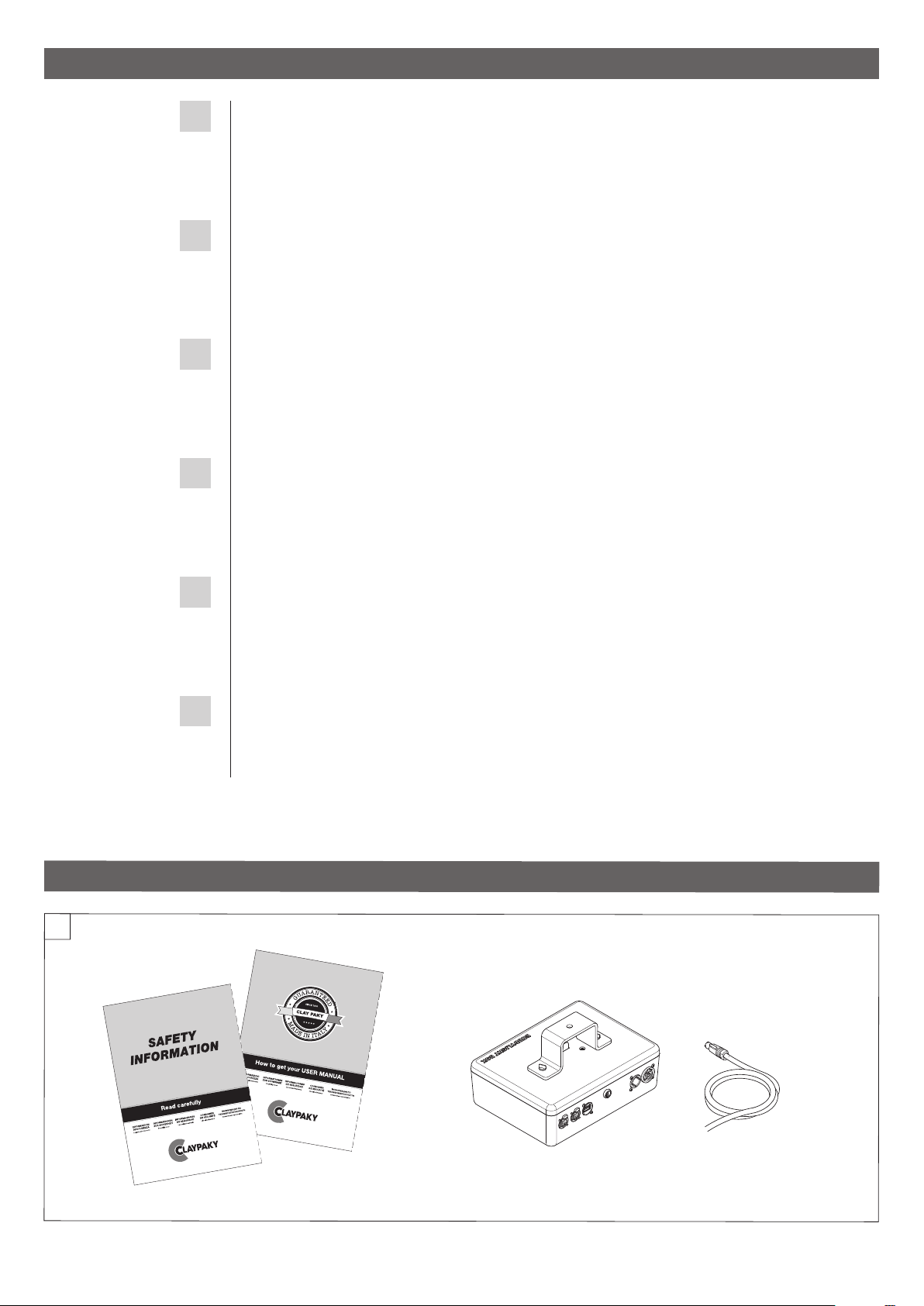
1. SAFETY INFORMATION
Packing contents - Fig. 1
1
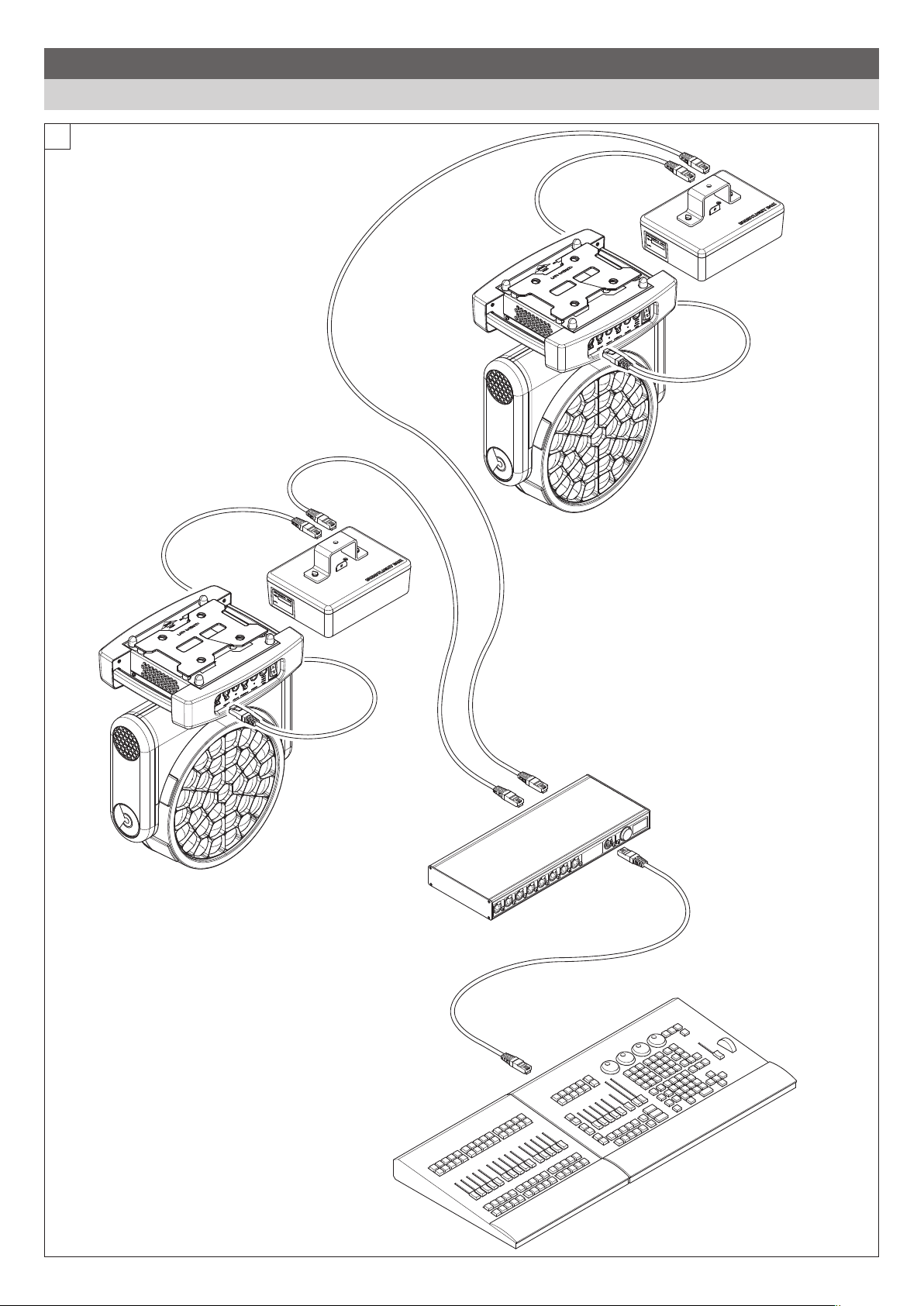
2. UNPACKING AND PREPARATION

3
BUDDYLIGHT
Art-Net NODE
LIGHTING CONSOLE
ETHERNET
CABLE
CLAYPAKY
FIXTURE
BUDDYLIGHT
BOX
CLAYPAKY
FIXTURE
BUDDYLIGHT
BOX
ETHERNET
CABLE
ETHERNET
CABLE
2
3. FULL SYSTEM LAYOUT TIPS AND CONSTRAINTS
Show setup with console
Continue ‘

4
BUDDYLIGHT
min.2,5 m
min.1,5 m
Anchor
A
B
Actor
tags
Leica
BUDDYLIGHT
Lighting fixture
A'
B'
CoR
3
CoR
min.2,5 m
min.1,5 m
A
B
B'
Actor
tags
Leica
Anchor
BUDDYLIGHT
Lighting
fixture
A'
4
Layout example 1
Layout example 2

5
BUDDYLIGHT
min.2,5 m
min.1,5 m
A
B
B'
Actor
tags
Leica
Anchor
BUDDYLIGHT
Lighting
fixture
A'
CoR
CoR
5
BUDDYLIGHT: BUDDYLIGHT Box - Fig. 3 - 4 - 5
Maximum tracking area volume: 15 x 15 x 15m
Leica: Laser distance meter.
Lighting fixture: One of the Claypaky fixtures supported by the BUDDYLIGHT System
Actor tag: BUDDYLIGHT TAG (2pcs) worn by the ACTOR
Anchor tag: BUDDYLIGHT HOLDER + BUDDYLIGHT TAG (8pcs placed as indicated on the picture).
A: Reference point (origin) on the stage floor, to be measured with the Leica laser distance meter during the calibration phase.
B: Reference point (x direction) on the stage floor, to be measured with the Leica laser distance meter during the calibration phase.
A’: Reference point (origin) on the truss on which the LIGHTING FIXTURE is mounted, to be measured with the Leica laser distance meter during the
calibration phase.
B’: Reference point (x direction) on the truss on which the LIGHTING FIXTURE is mounted, to be measured with the Leica laser distance meter
during the calibration phase.
CoR: Fixture Center of Rotation.
Layout example 3

6
BUDDYLIGHT
Status Reset
6
Lighting Fixture & BUDDYLIGHT Installation - Fig. 6
4. INSTALLATION AND START-UP
4.1 Installing the fixture + Box

7
BUDDYLIGHT
Art-Net NODE
ETHERNET
CABLE
POWER IN POWER OUT
POWER IN
LIGHTING CONSOLE
7
Lighting Fixture & BUDDYLIGHT Installation - Fig. 7
Continue ‘

8
BUDDYLIGHT
8
Lighting Fixture & BUDDYLIGHT Installation - Fig. 8

9
BUDDYLIGHT
min. 1,5 m
min. 2,5 m
9
4.2 Installing the anchors
Continue ‘

10
BUDDYLIGHT
Actor tags
10
4.3 Installing the TAG

11
BUDDYLIGHT
11
BUDDYLIGHT
4.4 General installation rules and tips
Continue ‘
BOX
1. The UWB radio module is installed along the clear side of the box, here below highlighted in gray: please install the box always with the clear
side facing the tracking area (stage).
2. Avoid installing the box upside down.
3. Is not mandatory to install the box nearby the connected fixture: it must be installed in a position where all the 8 installed anchors can be seen
and free from obstacles.
4. The Box must be installed in a higher position than Anchors.
5. The box must be installed inside the maximum tracking area volume (15 x 15 x 15m)
TAG
1. Please wear the TAG keeping the status led on top.
2. Avoid covering the TAG with metal parts or part of the body.
3. It is recommended to wear two TAGs (one on the front and one on the back) for better radio signal coverage.
4. For a stable tracking, do not hold the TAG in your hand but fix it on your body by means of the available clip or keeping it in your pocket.
ANCHOR
1. Please install the TAG and HOLDER keeping TAG in vertical position (status led on top).
2. The ANCHOR must be installed to delimit the tracking volume
- 4 ANCHORs must be installed at 2,5m (or in any case at an height higher than the actors moving on stage) in the four corner of the tracking area
- 4 ANCHORs must be installed higher than possible (but lower than BUDDYLIGHT Box) in the four corner of the tracking area.
6. The ANCHOR has not to be shielded by metal parts.
7. The ANCHOR must be installed inside the maximum tracking area volume (15 x 15 x 15m). They indeed depict the tracking area boundaries.

12
BUDDYLIGHT
FIXTURE
1. The fixture controlled by BUDDYLIGHT must be installed hanged upside down: floor and wall installation are not supported.
2. The fixture must be installed parallel to the truss and perpendicular to the ground.
3. PAN and TILT movement must be calibrated: with DMX at 50% the TILT must point perpendicular to the ground and the PAN must be parallel to
the fixture front display.
4. The fixture can be installed outside the 15x15x15m tracking area volume.

13
BUDDYLIGHT
Status Reset
StatusReset
Ethernet 1 Ethernet 2 USBFuse Power IN Power OUT
11
4.5 Connecting
Control Panel - Fig. 11
Ethernet 1: Gigabit Ethernet for Art-Net connection to the Lighting console
Ethernet 2: Fast Ethernet for Art-Net connection to the Fixture
PowerCon IN: Main power input
PowerCon OUT: Main power out
USB 2.0: USB port for manual mode mouse trackball connection.
Fuse
Reset: default reset parameter button
Continue ‘

14
BUDDYLIGHT
2
1
1
2
3
12
Connecting and disconnecting power cable - Fig. 12
BUDDYLIGHT Box LED
The meaning of LED colors for BUDDYLIGHT Box are listed in the table below.
Color Behavior
Led Off Box is turned off
Flashing White Box OS is starting up
Flashing Red Box error or Fixture not connected
Flashing Yellow Box in configuration mode or waiting for a valid configuration
Flashing Magenta Box has started a setup localization and the tracking of configured tag is active
(only for the last step of the wizard configuration process)
Flashing Green Box correctly configured and running as configured.
Flashing Cyan Box in firmware update mode (triggered via UI “Box Software Upgrade” or “Nodes Software Upgrade“)
BUDDYLIGHT Box Button
Action Behavior
Reset button simple press Soft Reset. Reset Wi-Fi settings as default factory values and reboot the Box.As configured in the UI.
Reset button long press Hard reset. Reset Wi-Fi settings as default factory values and remove, if present, current
BUDDYLIGHT configuration. This operation can’t be undone. Finally reboot the Box.

15
BUDDYLIGHT
BUDDYLIGHT LED
The meaning of LED colors for BUDDYLIGHT TAG portable devices are listed in the table below.
FIXED LED SLOW BLINK
1 blink per second
FAST BLINK
2 blinks per seconds
FASTER BLINK
4 blinks per seconds
White Unconfigured Node with
battery charger connected
and battery fully charged.
Unconfigured Node with
battery charger disconnected
(battery powered).
Unconfigured Node with
battery charger connected
battery is charging).
Green Tag Node with battery
charger connected and
battery fully charged.
Tag Node with battery
charger disconnected
(battery powered).
Tag Node with battery
charger connected
(battery is charging).
Hardware test passed when
triggered from button sequence
when BUDDYLIGHT node is turned
on with all button pressed
Blue Anchor Node with battery
charger connected and
battery fully charged.
Anchor Node with battery
charger disconnected (battery
powered).
Anchor Node with battery
charger connected (battery
is charging).
White-Red Unconfigured Node with
battery charger disconnected
(battery powered) and battery
charge below 20%.
Green-Red Tag Node with battery charger
disconnected (battery powered)
and battery charge below 20%.
Blue-Red Anchor Node with battery
charger disconnected (battery
powered) and battery charge
below 20%.
Red Battery powered Buddylight
with battery completely
discharged
• Hardware test fail triggered
from button sequence when
BUDDYLIGHT node is turned on
with all button pressed
• Hardware test fail on
firmware startup. BUDDYLIGHT
node has performed a self test
hardware on firmware startup
Yellow Waiting for Firmware update via
UWB. Device is waiting for a valid
firmware to download via UWB.
Yellow-Red UWB Bootloader Mode.
Temporary error on UWB
firmware update.
Yellow-Green UWB Bootloader Mode. Device
is updating firmware via UWB.
Multicolor
(Green-Blue-
Pink-Cyan)
Identify mode. During
configuration this led sequence is
used to identify a specific
BUDDYLIGHT node.
Action Behavior
Button 1 press and release As configured in the UI. Only for devices configured as tags
Button 2 press and release As configured in the UI. Only for devices configured as tags
Button 3 press and release As configured in the UI. Only for devices configured as tags
Button 1,2,3 pressed while device
is turning on from the switch
Performs a device factory reset and the hardware test.
The result of the test is showed with the led.
BUDDYLIGHT Buttons
Continue ‘

16
BUDDYLIGHT
4.6 Allowed network topologies
Control deskControl desk
13
Stand alone
This is the simplest case
and it’s just a single BUDDYLIGHT Box
controlling a single fixture via Art-Net.
Basic requirements are needed
to support this case.
Stand alone on a DMX network
In this case, the fixture has
a key role in the scenario.
It has to autonomously merge
what comes from the
Art-Net line and from the DMX line.
Basically, one will override
the other.
Art-Net repeater
In this case, the console must know the BUDDYLIGHT
DMX address and can control it (enable/disable)
The Box will repeat
the Art-Net DMX data and override
the channels it controls, programmed
by the user. Maximum
Universes supported
should be 8.
Art-Net on DMX network
In this usage case, an Art-Net console is controlling
the BUDDYLIGHT Box and at the same time
is outputting DMX data on a DMX line.
The BUDDYLIGHT Box will receive a Universe
including only “control”
channels: enable/disable,
which DMX channels
to override.
Art-Net on an Art-Net network
In this case the BUDDYLIGHT Box will receive
the same Art-Net data of the fixtures,
but should only consider
the universe with the
“control” channels and
drop all the rest.

17
BUDDYLIGHT
5. BUDDYLIGHT WEB UI
5.1 Home page
At startup, to allow the user to access to the web server user interface, the BUDDYLIGHT Box exposes a Wi-Fi network with the following parameters:
• SSID: “BL-Box-12345678”
• Password: “track-me!”
• Encryption: AES
• IP Address: 192.168.1.2
• DHCP range: 192.168.1.002 – 192.168.1.010
Once connected to the web server, the home page is displayed.
By means of this page the user can access:
Settings
General system information, settings and firmware upgrade.
Setup Wizard
Wizard that guides the user on the system configuration process, to be performed at the installation phase or every time a device (Box, Tag or
Anchor) is added or removed.
Calibration Wizard
Wizard that guides the user on the system calibration process, to be performed once the Box and Anchors have been installed or changed in position.
NOTE: At the first login, the user will first be asked to customize the default Wi-Fi parameters. Please refer to the Settings chapter (5.4) for
further information
Continue ‘

18
BUDDYLIGHT
▲
BACK
5.2 Setup Wizard
Setup Wizard - Start page.
The Wizard guides the user through the configuration steps:
1. Discovery of available BUDDYLIGHT Box in the network.
2. Check of the connected lighting fixtures.
3. Definition of BUDDYLIGHT Box DMX Address and Universe.
4. Definition of default tracking scenes.
5. Discovery of available NODES (TAGS and ANCHORS).
6. Configuration of NODES as TAG or ANCHORS.
7. TAG Group definition.
8. TAG push button configuration.
Next
Go to the next step of the wizard.
NEXT
▼
Setup Wizard - Discovery of available BUDDYLIGHT Box in the network
This page lists all the BUDDYLIGHT Box discovered, indicating for each one the
related name (customizable) and MAC Address.
The Green indicator highlights the BUDDYLIGHT Box to which the user is connected
via Webserver GUI.
Back
Go to the previous step of the wizard.
Next
Go to the next step of the wizard.
NEXT
▼

19
BUDDYLIGHT
Setup Wizard - Check of the connected lighting fixtures.
By means of this page the user can check the information related to the lighting
fixture connected to the discovered BUDDYLIGHT Box.
Bl-Box-xxxxxx
Push Button used to select the desired BUDDYLIGHT Box.
Fixture Model/Address/DMX Universe/IP Address
Information related to the Lighting fixture connected to the selected BUDDYLIGHT Box.
Note: Fixture universe must be set to 0 to be detected by BUDDYLIGHT box.
Identify
Enable/Disable the fixture identification.
Preset Fixture Channels
Page to define the default tracking scene.
Console Control
If enabled, the BUDDYLIGHT Box can be controlled as an Art-Net device from a
Console (refer to BUDDYLIGHT Box DMX Personality).
Universe
BUDDYLIGHT DMX Universe.
DMX Address
BUDDYLIGHT DMX Address.
Back
Go to the previous step of the wizard.
Next
Go to the next step of the wizard (Node Setup). This Push button becomes active
only if the user has checked all the connected fixture information
NEXT
▼
Continue ‘

20
BUDDYLIGHT
▲
BACK
▲
BACK
Setup Wizard/Preset Fixture Channels - Definition of default tracking scenes
In this page the user can define, acting on all the DMX Channels of the connected
lighting fixture, the default scene to be used during the tracking in stand alone mode
(BUDDYLIGHT Box not connected to a Lighting console).
Save
Saves current settings.
Back
Go to the previous step of the wizard.
NEXT
▼
Setup Wizard – Discovery of available NODES (TAGS and ANCHORS)
This page lists, for each discovered nodes, the unique ID, the Name, the Type (role)
and the power supply status (Battery level or in charge).
By means of this page the user has to define the role (TAG or ANCHOR) for each
discovered node and, if desired, assign a custom name.
“…”
Access to the Node configuration page.
Next
Go to the next step of the wizard (Edit Tag Groups). This Push button becomes active
only if the user has configured all the discovered nodes.
Back
Go to the previous step of the wizard
Table of contents
Other ARRI Controllers manuals