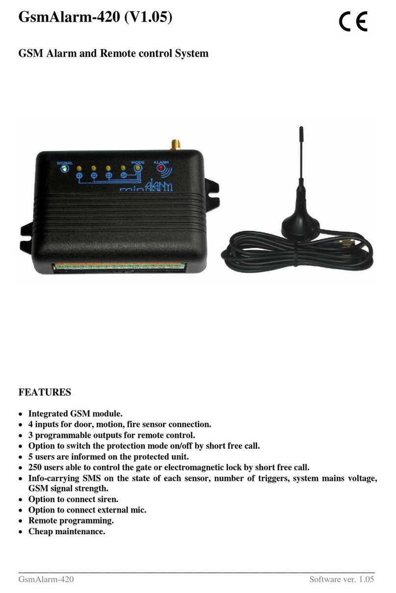
ELT GsmAlarm-300 User manual

GSM resender_______________ GsmAlarm-300
____________________________________________________________________________________
1
Gs mAla rm-3 00
Central
Sta tion
PSTN line
Ala rm S ystem
and
Transm itter
GSM Network
Phone
Line Test
Switch
to GSM
1. GENERAL DESCRIPTION
GsmAlarm-300 provides for reliable double-sided security system communication with the central
station through GSM network.
In the case of wire telephone line failure, GsmAlarm-300 automatically switches the security system
telephone output to the integrated GSM module and the data is relayed to the security panel through
GSM network.
GsmAlarm-300 may be used with any types of security systems, maintaining audible data transfering
protocols: FSK (10 to 300 bauds), DTMF etc.
GsmAlarm-300 is operable in any GSM network of 900/1800 MHz.
GsmAlarm-300 may have up to 4 users. Users may call the GsmAlarm-300 number and control the
system from their phones using DTMF instructions as follows:
connect to the GSM service provider's operator and learn balance of the SIM card account;
ask for SMS, carrying programmed numbers of the users, SMS center and GSM operator's
information;
ask for SMS, carrying information about GsmAlarm-300 communication quality and power
source voltage.
Caling user is identified by his phone number. If the call comes not from the user's phone, the call is
immediately cancelled. In order to check system operation, user shall briefly call GsmAlarm number.
GsmAlarm-300 within 10-20 seconds answers the caller with a brief ringer tone.
All the GsmAlarm-300 user numbers, SMS center number and brief information number are
programmed by a single SMS with an 8-character password in the beginning of such SMS.
GsmAlarm-300 has a GSM communication failure alarm output as well as a wire line (PSTN) failure
alarm output.
GsmAlarm-300 is very easy to install. State of the device may be quickly evaluated using indication of 4
LEDs.

GSM resender_______________ GsmAlarm-300
____________________________________________________________________________________
2
2. INSTALLATION
2.1 CABLING AND CONNECTING
2.1.1. Connect antenna to GSM module. Antenna shall be positioned as far from the GsmAlarm-
300 module as possible. No winded antenna cable is recommended to be left near the
GsmAlarm-300.
2.1.2. Insert a SIM card with PIN code OFF.
2.1.3. Connect the CENT contacts to the security centrale telephone line input. During testing,
parallel ordinary phone device with tone dial may be connected.
2.1.4. Connect the contacts +12V and GND to the protection system power source.
2.1.5. Contacts LINE are used to connect the wire telephone line. The telephone line is advised to
connect later - in the end of adjustment.
2.1.6. The contact C2 (PSTN Fail) - MOSFET "open drain" output - is used to warn about the
telephone line (PSTN) failure. This output is activated (connected with the ground wire
GND) in the case of telephone line failure after 15 seconds.
2.1.7. The contact C3 (GSM Fail) –MOSFET "open drain" output - is used to warn about GSM
communication failure. This output is activated (connected with the ground wire GND) in the
case of GSM communication failure after 15 seconds.
2.1.8. Reserve contacts Z1 and Z2 inside the GsmAlarm-300 module are free and may be used to
connect additional wires (e.g. tamper circuitry).
LINECENT
GSMAntenna
Tel.
Line Ground
SIM
Card
GsmAlarm-300
Dual Band Module
+12V GND
POWER
Supply
10.5 ... 15V
+-
Z2Z1
Reserved
Contacts
GSM900/1800
Dialler
MODEM MODE READY LINE
Reader
Visual indicators (LEDs)
Connector
To
In
C2C3
GSM
Fail PSTN
Fail

GSM resender_______________ GsmAlarm-300
____________________________________________________________________________________
3
2.1.9. In order to protect the device against electrical discharges, connect the contact Ground to
ground wire of the building by a separate wire.
2.2. PURPOSE OF THE LEDs
2.2.1. MODEM (red) - indicates GSM module operation state.
Out - GSM module is not in use.
Continuously On - GSM module is in use, but there is no GSM operator network
registration.
Blinking once a 2-3 seconds - GSM module is in use, GSM operator network
registration is present - everything is OK.
2.2.2. MODE (yellow) - indicates GsmAlarm-300 operation mode.
Out - system is not active.
Continuously On - CENT line is active (handset is lifted).
Blinking once a second - outgoing call, speech mode or SMS is being sent.
Blinking more frequently than once a second - incoming call.
Blinking very rapidly - correct DTMF or SMS instruction confirmation.
2.2.3. READY (green) system state indicator.
Out - system is not operating.
Blinking - system is operating, but no SMS center nor a single user number have been
programmed.
Continuously On - system is ready for work.
2.2.4. LINE (red) - wire telephone line indicator
Out - no wire line (LINE), communicating through GSM network.
Continuously On - wire line (LINE) is present, communicating through wire line.
3. PROGRAMMING
GsmAlarm-300 may be used without additional programming, however in order to employ all its
features, we advise to program the SMS center number, at least one user telephone number and GSM
operator's information brief number. Then the user is enabled to
check SIM card account balance, as well as to control the system by DTMF and SMS instructions.
3.1 SMS CENTER AND USER NUMBER PROGRAMMING
In order to program SMS center and user numbers, send GsmAlarm-300 a SMS with the following
contents:
AAAAAAAA SMSNR:123456789 ALRNR1:123456789 ALRNR2:123456789
ALRNR3:123456789 ALRNR4:1234546789 SRVNR:1234
AAAAAAAA is an 8-digit SMS password, necessary to enter in the beginning of each SMS.
Manufacturer has programmed it as AAAAAAAA. User may change this password as he wants
(see 3.2).

GSM resender_______________ GsmAlarm-300
____________________________________________________________________________________
4
ALRNR1 - ALRNR4 - user numbers. GsmAlarm-300 may be called exclusively from these
numbers. Calls from another numbers are ignored and cancelled immediately.
SVRNR - brief service number, used to check SIM card account balance. When user calls the
GsmAlarm-300 number and enters the correct code (four asterisks), GsmAlarm-300 calls the
programmed brief number and connects user with operator. Then user shall push the button,
specified by the operator and receive information of the GsmAlarm-300 SIM card account balance.
If programmed correctly, user gets a SMS with newly programmed numbers.
3.2 CHANGING SMS PASSWORD
In order to change manufacturer-programmed SMS password, send GsmAlarm-300 the following
SMS:
AAAAAAAA PASSW:ABCDefgh
AAAAAAAA - old password.
PASSW - password change instruction.
ABCDefgh - new SMS password. It must have 8 digits!
If programming instruction is executed successfully, user gets a confirmation SMS with new
password.
3.2 INFORMATION SMS
In order to receive a SMS carrying programmed numbers and password, send GsmAlarm-300 the
following SMS:
AAAAAAAA NRINFO
In order to receive a SMS carrying information about GSM signal strength and power source
voltage, send GsmAlarm-300 the following SMS:
AAAAAAAA PRINFO

GSM resender_______________ GsmAlarm-300
____________________________________________________________________________________
5
4. POSSIBLE PROBLEMS AND THEIR CAUSES
After swithing on the GsmAlarm-300 power source, device becomes fully operable within 15-30s.
GsmAlarm-300 starts working, after:
MODEM LED is blinking once a 2-3s;
READY LED is continuouslu on.
Find out the problem with the means of LED indications.
LED state
Possible causes
No LED is on.
No power source voltage
MODEM LED is continuously on,
READY and MODE LEDs are Off.
1. No SIM card.
2. PIN code is not off.
3. No GSM antenna is connected.
4. Poor communication quality with GSM operator.
READY LED is blinking.
No SMS or user numbers are programmed.
5. CONTROL WITH DTMF INSTRUCTIONS
By calling GsmAlarm-300, user may control the system with DTMF instructions. GsmAlarm-300
answers after 3-4 calling tones, user hears three confirming tones.
DTMF instruction
Purpose
****
Connection with GSM operator, account balance
checking.
Note: this command is operating only if the brief
number SRVNR has been programmed and if
GSM operator conference communication service
is on!
91*
Request to send SMS carrying SMS password and
programmed numbers.
92*
Request to send SMS carrying information about
signal quality and power source voltage.
6. PARAMETER RESET TO MANUFACTURER's VALUES
In order to reset the system parameters into the manufacturer's values (SMS password: AAAAAAAA,
all numbers deleted), perform as follows:
switch off power source;
insert RESET jumper;
switch on power source, wait for MODEM LED to become On;
switch off power source;
take off RESET jumper.

GSM resender_______________ GsmAlarm-300
____________________________________________________________________________________
6
7. TECHNICAL SPECIFICATIONS
Wire line emulator
Emulation of a regular telephone line
Dialling: DTMF only
Wire line input
Input impedance
Checking of line voltage
Line identification voltage
>1 MΩ
continuous
>6 V
Outputs C2 (GSM Fail) and C3 (PSTN Fail)
Type
Active state
Inactive state
Maximum commutated current
Maximum commutated voltage
Resistance in active level
MOSFET, open drain
Connected with GND
Open contact
200mA
20 V
<40 Ω
GSM module
Operation frequency
Maximum RF output power
900/1800 MHz
2W/1W
Wire line - GSM commutator
relay
Power source voltage
10.5 ... 15V, DC
Current consumption
Non-activated state, wire line is on
Non-activated state, wire line is off
SMS sending or speech mode
<80 mA
<60 mA
<330 mA
Dimensions
140 x 58 x 16 mm
Table of contents
Other ELT Security System manuals
Popular Security System manuals by other brands

Addmore
Addmore ESS260R installation manual

Barnacle Systems
Barnacle Systems BRNKL Setup guide

Coopers of Stortford
Coopers of Stortford 10712 Instrucons for Use
MAKS
MAKS PRO manual
Pentair Jung Pumpen
Pentair Jung Pumpen AG3 instruction manual

Amperes Electronics
Amperes Electronics EP1200 instruction manual
