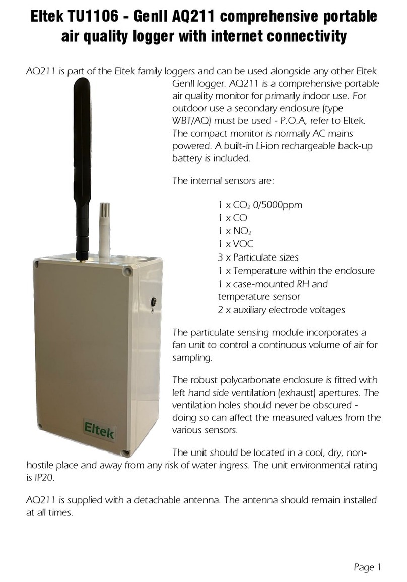
Eltek Squirrel 1000 Series User manual

1
Table Of Contents
1. Introduction.............................................................................4
2. The functions of the datalogger .............................................5
2.1 LOG................................................................................5
2.2 METER...........................................................................5
2.3 REVIEW .........................................................................5
2.4 TIME / date.....................................................................5
2.5 START time / date...........................................................5
2.6 INT log / sample (logging/sampling interval) ....................5
2.7 OUTPUT.........................................................................5
2.8 MODE.............................................................................6
2.9 CHANNEL SETUP..........................................................6
2.10 STAT (status).................................................................6
3. How to start logging from the default settings......................7
3.1 Set time/date...................................................................7
3.2 Select logging interval.....................................................8
3.3 Set the type of logging required.......................................8
3.4 Set the number and types of channels.............................9
3.5 Start logging..................................................................11
3.6 Stop logging..................................................................12
4. More about the functions of the datalogger ........................13
4.1 The LOG function..........................................................13
4.2 The METER function.....................................................15
4.3 The REVIEW function...................................................16
4.4 The TIME and date function..........................................17
4.5 The delayed START function.........................................17
4.6 The INT function (logging/sampling interval)..................19
4.7 The OUTPUT function...................................................20
4.8 The MODE function.......................................................21
4.9 The CHANNEL SETUP function....................................27
4.10 The STAT function.......................................................30
5. Connecting sensors/signals to the datalogger....................35
5.1 Wiring up thermistor sensors.........................................35
5.2 Wiring up platinum resistance sensors ..........................35
5.3 Wiring up sensors to voltage channels ..........................36
5.4 Wiring up sensors to current channels...........................36
5.5 How to provide a power supply to the sensors...............37
5.6 Wiring up Current Loop Sensors driven by the Squirrel..38

2
5.7 Wiring up an AC voltage input.......................................38
5.8 Wiring up a pulse count channel....................................39
5.9 Wiring up event channels..............................................40
5.10 Wiring up for external triggers ......................................41
6. Troubleshooting guide .........................................................42
6.1 “Why won’t it do that?”...................................................42
7. Memory Card Squirrels (1000 series only)...........................43
7.1 Types Of Card...............................................................43
7.2 Preparing the Card........................................................43
7.3 Squirrel Settings............................................................43
7.4 Extracting the data........................................................46
8. Electricity Squirrels (1010, 1020)..........................................48
8.1 Logger functions ...........................................................48
8.2 Selecting ranges...........................................................48
8.3 Making connections to the datalogger ...........................49
9. Squirrels with pH channels ..................................................50
9.1 Channel Selection.........................................................50
9.2 Pre-setting the Temperature..........................................50
9.3 Choosing the Calibration Point......................................51
9.4 Calibrating the Midpoint (pH7.0)....................................51
9.5 Calibrating the Slope.....................................................52
9.6 Current Consumption and Battery Life...........................52
9.7 Care and Use of pH Probes ..........................................53
10. Special Instructions..............................................................54
10.1 Alarms.........................................................................54
10.2 Wind Speed & Direction...............................................55
11. Fast Logging (1000 series only) ..........................................57
11.1 Logging Interval...........................................................57
11.2 Translation with Darca .................................................57
11.3 Darca Contact..............................................................58
12. Safety and operating conditions ..........................................59
12.1 Operator safety............................................................59
12.2 Squirrel safety..............................................................59
12.3 Errors caused by ground connections ..........................59
12.4 Operating conditions....................................................59
12.5 Protection against memory loss....................................60
12.6 Changing batteries.......................................................60
12.7 Resetting the datalogger..............................................60

3
12.8 Changing fuses............................................................61
12.9 Changing memory........................................................61
12.10 Sensor supply voltage ................................................62
13. Technical data.......................................................................63
13.1 Inputs, ranges and resolutions .....................................63
13.2 Specification................................................................64
14. Connectivity ..........................................................................65
14.1 Signal connector..........................................................65
14.2 Output connector (for connection to a PC)....................65
Declaration of Conformity ..............................................................67
Manufacturer...........................................................................67
Description of Equipment........................................................67
Applied Standards...................................................................67

4
1. Introduction
This user manual covers the operation and configuration of the Squirrel
datalogger via the three operating buttons on its front panel. The Squirrel
can also be configured and operated from a connected PC running Eltek’s
Darca software. The operating buttons on the front of the logger allow the
setup of nearly all of the major functions of the logger, but some functions
can only be accessed through Darca. These include:
·Scaling EU units in a channel
·SMS Alarm operation
For more information on using Darca, consult the document TM1020.
Overview of the operating buttons
function selects the function.
select selects the channel or
sub function.
set is used to change any of
the settings.
To switch the datalogger on,press and hold function. To switch it off,
leave in LOG or OUTPUT function for a few seconds. If the datalogger is
left on in any other function, it will automatically switch off after 4 minutes.

5
2. The functions of the datalogger
Listed in the order they appear when scrolling with the function button.
2.1 LOG
Used to start and stop logging. In addition, this function displays the
number of readings already stored in the memory (used), and the number
of readings that may be stored in the remaining memory (free). All the
readings stored in memory may be erased in this function. In addition, this
function will allow you to display how many separate runs have been
recorded.
2.2 METER
Displays the value of the channels that have been selected, in the
appropriate units. The readings are updated every second.
2.3 REVIEW
Displays the recorded values of the selected channels, starting with the
first reading in the last run (if the logger is not currently logging). If the
logger is currently logging, then the first reading in the current run is
displayed.
2.4 TIME / date
Displays the real time and date on two lines. The 24 hour clock may be
displayed in the appropriate country format (see 2.10f); the time
increments every second.
2.5 START time / date
This option allows you to set a future time and date at which logging will
start.
2.6 INT log / sample (logging/sampling interval)
The interval function is used to set the time intervals at which readings are
taken and stored in memory. The logging interval can be set between 1
second and 24 hours in 1-second increments. The second line is used to
set the time intervals at which inputs are sampled; these readings are
averaged and then stored in memory at the logging interval.
2.7 OUTPUT
Used for output of recorded data to a computer. During downloading of
data, the LCD displays the number of blocks to be downloaded and this is
decremented after each successful transmission of a block. No baud rate

6
setting is required as it is automatically selected.
2.8 MODE
Used to select the type of logging required, namely Interval, Average,
Event, Event+Interval, Event+Average. This function allows you to select
how logging may be started and stopped via an external trigger, if
required. In addition, you can select whether you wish logging to stop
when the memory is full or whether logging continues and old data is
overwritten.
2.9 CHANNEL SETUP
Used to select the channels from which you require data to be recorded.
The range for each channel is also selected, which could include
engineering units if these have been set up by Darca. This function also
displays how many channels have been selected to record.
2.10 STAT (status)
This function displays the following status information concerning the
datalogger: -
a) internal battery voltage and number of days remaining of viable battery
life when logging
b) external supply voltage
c) memory size (with the ability to change memory size in 1K increments)
d) sensor power-on time (up to 60 seconds before the reading is taken)
e) date format configuration (adjustable)
f) language format (adjustable)
g) mains frequency filter (adjustable)
h) model number and current version of firmware
i) temperature units (thermocouple Squirrels only)
j) network option (if enabled with Darca software)

7
3. How to start logging from the default settings
3.1 Set time/date
The real time and date are displayed on two lines. The time is set in the
format HH:MM:SS. and the date default format is DD/MM/YY. Press
function until the display shows: -
T
I
M
E
1
0
:
4
2
:
5
9
d
a
t
e
2
5
/
1
2
/
9
4
Press set and the following prompt appears: -
T
I
M
E
1
0
:
4
3
:
1
1
H
O
L
D
T
O
C
H
A
N
G
E
Hold set button and cursor will appear: - (the clock will stop)
T
I
M
E
1
0
:
4
3
:
1
7
d
a
t
e
2
5
/
1
2
/
9
4
Press select to move cursor: -
T
I
M
E
1
0
:
4
3
:
1
7
d
a
t
e
2
5
/
1
3
/
9
4
Press set to change value: -
T
I
M
E
1
0
:
4
6
:
1
7
d
a
t
e
2
5
/
1
2
/
9
4
Press function when settings are correct: - (cursor will disappear and
clock will restart with new settings).
T
I
M
E
1
0
:
4
6
:
1
9
d
a
t
e
2
5
/
1
2
/
9
4
If invalid data is entered, the display changes the settings to the nearest
valid time/date.

8
3.2 Select logging interval
The logging interval can be set between 1 second and 24 hours in 1-
second increments. Recordings are stored at this interval. Press function
until display shows: -
I
N
T
l
o
g
0
0
:
0
0
:
3
0
s
a
m
p
l
e
0
0
:
0
0
:
0
0
Press set to display: -
I
N
T
l
o
g
0
0
:
0
0
:
3
0
H
O
L
D
T
O
C
H
A
N
G
E
Hold set button and cursor will appear: -
I
N
T
l
o
g
0
0
:
0
0
:
3
0
s
a
m
p
l
e
0
0
:
0
0
:
0
0
Press select to move cursor: -
I
N
T
l
o
g
0
0
:
0
0
:
3
0
s
a
m
p
l
e
0
0
:
0
0
:
0
0
Press set to change value: -
I
N
T
l
o
g
0
0
:
0
0
:
3
5
s
a
m
p
l
e
0
0
:
0
0
:
0
0
This example changes the logging interval from 30 to 35 seconds. Press
function to clear the cursor and to continue with setup.
3.3 Set the type of logging required
The possible types of logging are detailed in section 4.8.1. However, the
default setting is for recording data at fixed intervals only. Press function
until mode is displayed: -
M
O
D
E
l
o
g
i
n
t
e
r
v
a
l
You need do nothing else except set which channels to log if you simply

9
need to record data at the logging intervals set in section 3.2.
3.4 Set the number and types of channels
Each model has a specified combination of channels, please consult the
data sheet in Section 13 for details of your particular model. This section
will guide you to set up a temperature and voltage/current channel. Press
function until the following is displayed: -
C
H
A
N
N
E
L
S
E
T
U
P
1
u
s
e
d
The default setting will always be the first range of the first channel. If you
deselect all channels, then you will not be able to progress until you have
configured at least one channel. In this case, pressing the function key will
only display the following message: -
C
H
A
N
N
E
L
S
E
T
U
P
N
O
N
E
S
E
L
E
C
T
E
D
Please proceed to the following sections for instructions on how to set up
specific channels.
3.4.1 Temperature channel setup
Thermistors, thermocouples and platinum resistance sensors are capable
of accurately measuring temperatures within different ranges. This
example is for a datalogger with thermistor type inputs. Press select once
and the following message will be displayed: - (Pressing select several
times will allow you to scroll through the channels)
C
H
1
°
C
-
3
0
.
0
/
7
0
.
0
Press set and hold for 3 seconds: -
C
H
1
°
C
H
O
L
D
T
O
C
H
A
N
G
E
C
H
1
°
C
-
5
0
.
0
/
1
5
0
.
0

10
The temperature range then increments to the next available range with
every press of the set button: -
C
H
1
°
F
-
2
2
.
0
/
1
5
8
.
0
Leave the display showing your chosen range and press select to set up
another channel.
3.4.2 Voltage/current channel setup
These channels may be configured for voltage or current. There are
typically 18 voltage ranges and 2 current ranges. Voltage/current
channels have an additional range called the EU (Engineering Units)
range where the user can select specific engineering units (e.g. m/s) and
a max/min scale (e.g. 0/50 m/s). The appropriate voltage/current range is
then selected from the existing hardware ranges (e.g. 0/1 V). In the above
example, 0/50 m/s = 0/1V and the display in METER mode will show
readings in m/s. All data in this channel will be stored and downloaded
using m/s as the unit. In the above example, the CHANNEL SETUP
function will alternate between the following displays: -
C
H
6
E
U
m
/
s
0
.
0
/
5
0
.
0
C
H
6
E
U
V
0
.
0
0
0
/
1
.
0
0
0
The EU range may only be set up using Darca (please see price list or
contact your distributor for details). Whenever a voltage/current channel
has not been set up, the initial range is always the default EU range and is
displayed as follows: -
C
H
6
E
U
%
0
.
0
/
1
0
0
.
0
C
H
6
E
U
V
0
.
0
0
0
/
1
.
0
0
0
Press select to change channel. For example, select channel 5: -

11
C
H
5
n
o
t
u
s
e
d
Press set and hold for 3 seconds: -
C
H
5
H
O
L
D
T
O
C
H
A
N
G
E
Now press set to scroll through the voltage/current ranges. Leave the
display showing your chosen range and press select to set up another
channel or press function to continue with logger setup.
3.4.3 Humidity channel setup
The default EU (Engineering Unit) range for all voltage/current inputs (as
described in 4.4.2), is 0/1V = 0/100% which is suitable for probes such as
the EplusE EE08 and Rotronic Hygroclip S3/HC2. These probes plug into
any voltage/current input selected using the CHANNEL SETUP function.
Press and hold set for 3 seconds to change an unused voltage/current
channel to the default EU range. N.B. It is essential that the ‘sensor on’
time is set to 1 second or greater. Please see 4.10.4 for further
details.
3.5 Start logging
Press function until the following is displayed: -
L
O
G
o
f
f
u
s
e
d
0
Now press and hold set to start logging: -
L
O
G
o
f
f
H
O
L
D
T
O
S
T
A
R
T
The display shows that logging has started and will turn off within 10
seconds to conserve power. (Some memory slots will be used up
immediately in order to store the header file.)
L
O
G
o
n
u
s
e
d
1
4

12
3.6 Stop logging
Press function to wake up the logger: -
L
O
G
o
n
u
s
e
d
1
2
3
Hold set to stop logging: -
L
O
G
o
n
H
O
L
D
T
O
S
T
O
P
L
O
G
o
f
f
u
s
e
d
1
2
3

13
4. More about the functions of the datalogger
4.1 The LOG function
4.1.1 Logging status displays
Whenever function is pressed while the logger display is blank, the display
will indicate the logging state. This indicates that logging is in progress
and that 123 memory slots have been used so far: -
L
O
G
o
n
u
s
e
d
1
2
3
Alternatively, the display below indicates that logging has stopped and
that 124 memory slots have been used: -
L
O
G
o
f
f
u
s
e
d
1
2
4
If the START function has been used (see 0), the logger waits for a
specific time and date to start logging, and the following is displayed: -
L
O
G
w
a
i
t
i
n
g
u
s
e
d
0
Alternatively, this may indicate that externally triggered recording has
been selected (see 4.8.7), in which case logging may be started by an
external trigger (e.g. a machine switching on).
4.1.2 Used / free memory / number of runs recorded
Whenever the LOG function is entered, press select to scroll through sub-
functions. The first screen displays the number of memory slots already
used for storage of data and header blocks:
L
O
G
o
f
f
u
s
e
d
1
0
0
The next screen displays the number of memory slots available for further
logging:
L
O
G
o
f
f
f
r
e
e
6
4
9
0
0

14
The number of separate runs already recorded (out of a maximum of 99)
is displayed in the last screen. If the logger is logging, then the current run
number is displayed:
L
O
G
o
f
f
r
u
n
3
4.1.3 Start/stop logging
If you have just unpacked your datalogger and have not previously used
this model then please go to section 3. Whenever you first enter the LOG
function you can press and hold set to start and stop logging: -
L
O
G
o
f
f
u
s
e
d
1
2
3
4
5
L
O
G
o
n
u
s
e
d
1
2
3
4
5
N.B. you can only start and stop logging when the display shows either of
these screens.
4.1.4 How to clear the memory
The procedure for clearing the memory has been designed to reduce the
risk of the user accidentally clearing the memory. It is not possible to clear
the memory while either logging or waiting to log. It is only possible to
clear the memory using the following sequence:
Press function to wake up the datalogger and press select within 10
seconds to obtain either of the following displays: -
L
O
G
o
f
f
f
r
e
e
1
2
3
4
5
L
O
G
o
f
f
r
u
n
3
Now you can clear the memory by pressing and holding set for 2 seconds:
L
O
G
o
f
f
H
O
L
D
T
O
C
L
E
A
R

15
4.2 The METER function
This displays the value of the selected channel using the currently
selected range for that channel. As soon as you enter the METER
function, the display will show the value of the first channel selected and
these values will be updated every second. This example assumes you
have selected the following channels: -
Channel 3 -30.0/70.0 °C
Channel 5 0.000/1.000 V
Channel 7 0.0/5.0V=0/500 Lux
As soon as you enter the METER function, the display will show: -
M
E
T
E
R
c
h
3
3
7
.
5
°
C
You may view the other channels by pressing select to scroll through
those that have been selected:
M
E
T
E
R
c
h
5
0
.
3
4
0
V
M
E
T
E
R
c
h
7
5
2
.
9
L
u
x
4.2.1 Pulse count channels
When viewing a pulse count channel in METER mode, the display will
show an accumulating total of pulse counts. This total may be reset to
zero by pressing set. Please note that zero reset will not be available
when logging is in progress; in this case, the accumulating total will be
automatically set to zero at the beginning of each logging interval. See
section 4.9.3 for further details.
4.2.2 Event/digital channels
The display will either show binary or decimal format, depending on which
has been selected in CHANNEL SETUP. See section 4.9.4 for further
details.
4.2.3 Elapsed time between events
An additional channel is automatically selected when you have selected
the following logging modes: - (See section 4.8 for further details)

16
M
O
D
E
l
o
g
e
v
e
n
t
M
O
D
E
l
o
g
e
v
e
n
t
+
i
n
t
e
r
v
a
l
M
O
D
E
l
o
g
e
v
e
n
t
+
a
v
e
r
a
g
e
M
O
D
E
e
x
t
e
r
n
a
l
t
r
i
g
g
e
r
r
e
c
o
r
d
s
This additional channel (which numerically follows the last physical
channel) is for measuring time between recordings. The number of
seconds that have elapsed between events or external triggers will be
displayed in this channel and may be viewed in METER mode: -
M
E
T
E
R
c
h
1
1
1
2
3
s
4.3 The REVIEW function
The display shows the recorded value of the selected channel, starting
with the first reading in the most recent run or the first reading in the
current run if logging is in progress. Press select to choose which channel
you wish to review. Once the channel has been selected, each press of
set will update the readings from first to last. A rotating bar indicates that
the next reading has been selected: -
R
E
V
I
E
W
c
h
2
2
0
.
3
°
C
-
R
E
V
I
E
W
c
h
2
2
0
.
2
°
C
\
R
E
V
I
E
W
c
h
2
2
0
.
4
°
C
|
Holding down set will display the readings rapidly until the following is

17
displayed: -
R
E
V
I
E
W
c
h
2
N
o
m
o
r
e
At any time you may skip to another channel and restart the review by
pressing select.
4.4 The TIME and date function
This displays the real time and date on two lines. The time clock is in a 24
hour format (HH:MM:SS). The format of the date may be changed for
using the STAT function. Please see section 3.1 for details of how to set
the time and date. Although invalid times and dates are allowed to be set,
when function is pressed, the entries are validated. The logger modifies
the entries to the nearest valid setting and displays a warning that the
initial entries were invalid. For example, the following would occur in UK
date format i.e. DD/MM/YY: -
T
I
M
E
1
0
:
4
3
:
1
7
d
a
t
e
2
5
/
1
3
/
9
4
T
I
M
E
1
0
:
4
3
:
1
7
I
N
V
A
L
I
D
-
C
H
E
C
K
!
T
I
M
E
1
0
:
4
3
:
1
7
d
a
t
e
2
5
/
1
2
/
9
4
The time and date cannot be altered if logging is in progress. Pressing set
will indicate this to the user:
T
I
M
E
1
0
:
4
4
:
3
4
L
O
G
G
I
N
G
4.5 The delayed START function
This function is used if you wish to set a future time and date at which
logging will start. Once you are in this function, press and hold set until
you obtain a cursor: -
S
T
A
R
T
0
0
:
0
0
:
0
0
0
1
/
0
1
/
9
4

18
Now press select to place the cursor under the entries that you need to
change: -
S
T
A
R
T
0
0
:
0
1
:
0
0
0
1
/
0
1
/
9
4
This entry may now be changed by pressing set until the desired value is
achieved: -
S
T
A
R
T
0
0
:
0
5
:
0
0
0
1
/
0
1
/
9
4
Other entries may be changed in a similar way, using select and set.
When the desired delayed start time and date has been set, you can
press function to store these parameters: -
S
T
A
R
T
0
0
:
0
5
:
5
5
3
1
/
1
2
/
9
4
It will usually be the case that the start time will be later than the current
real time and the logger will wait until the start time before commencing
logging. In this case, the following message will be displayed: -
S
T
A
R
T
0
0
:
0
5
:
5
5
d
e
l
a
y
e
d
s
t
a
r
t
N.B. Remember that you must also set the logger to start logging in
the LOG function (see 0). If you have set the start time and date to
earlier than the current real time then the following message is displayed:
S
T
A
R
T
0
0
:
0
5
:
5
5
i
m
m
e
d
i
a
t
e
s
t
a
r
t
Logging will then commence as soon as you set the logger to start
logging. At this time, the start time will automatically be adjusted to the
current real time. The start time and date cannot be altered if logging is in
progress or if the logger is waiting to start logging; this will be indicated by
the following message when set is pressed: -
S
T
A
R
T
0
0
:
0
5
:
5
5
L
O
G
G
I
N
G

19
Please note that invalid settings are treated as for time and date.
4.6 The INT function (logging/sampling interval)
Depending upon the logging mode selected (see 4.8), readings may be
stored in memory at fixed intervals or when certain events occur or a
combination of both of these. In the INT function the logging interval is
shown on the top line and can be set between 1 second and 24 hours
(unless ‘fast logging mode’is used –see section 11). In logging modes
that include averaging, the inputs are measured at a shorter interval
(called the sample interval) and the average of these measurements is
recorded at the logging interval. The sample interval is shown on the
bottom line and can be set between 1 second and 12 hours provided that
a logging mode including averaging is selected: -
M
O
D
E
l
o
g
a
v
e
r
a
g
e
M
O
D
E
l
o
g
e
v
e
n
t
+
a
v
e
r
a
g
e
If you have already selected either of the above modes but have not
selected a sampling interval, the following will be displayed: -
I
N
T
l
o
g
1
2
:
0
0
:
0
0
C
H
E
C
K
I
N
T
E
R
V
A
L
S
The logger will then automatically select a sampling interval of 1 second
for logging intervals up to and including 12 hours: -
I
N
T
l
o
g
1
2
:
0
0
:
0
0
s
a
m
p
l
e
0
0
:
0
0
:
0
1
A sampling interval of 2 seconds is the minimum for logging intervals over
12 hours. It is not necessary to change the sampling interval if recordings
are made in non-average logging modes. The sampling interval will be
automatically set to zero: -
I
N
T
l
o
g
1
2
:
0
0
:
0
0
s
a
m
p
l
e
0
0
:
0
0
:
0
0

20
Please note that the logging/sampling interval cannot be changed while
logging is in progress or while logging is waiting to commence:
I
N
T
l
o
g
1
2
:
0
0
:
0
0
L
O
G
G
I
N
G
4.7 The OUTPUT function
This function is used to output data to a computer using the following
programs: -
Data transfer and setup Darca Lite
Data transfer and analysis Darca Plus / Squirrelwise
Data transfer, direct/remote setup and analysis Darca Plus
Once you enter OUTPUT the display will clear and the datalogger will
quickly enter sleep mode, which is required prior to active communication.
The baud rate is automatically selected by the program that is used. Eltek
Squirrels with serial numbers 6000 and above will work at up to 38400
baud. During downloading, the number of blocks to be downloaded is
displayed and this number changes after each successful transmission of
a block. While not actively communicating, “idle”is displayed. An example
of some of the displays which may be seen during the downloading
process are shown below:
O
U
T
P
U
T
9
6
0
0
b
a
u
d
c
o
m
m
s
b
l
o
c
k
6
O
U
T
P
U
T
9
6
0
0
b
a
u
d
i
d
l
e
O
U
T
P
U
T
9
6
0
0
b
a
u
d
c
o
m
m
s
b
l
o
c
k
5
The number of blocks transmitted will decrement until the display clears to
indicate that all the data have been transferred. Please note that
downloading of data can be achieved while logging is in progress and that
the following minimum logging intervals are permissible, corresponding to
the appropriate baud rates: -
This manual suits for next models
2
Table of contents
Other Eltek Data Logger manuals
