ELTEX BASIX ES47 Series User manual
Operating Instructions
Discharging System BASIX
Series ES47 Power Supplies
for AC Operation
BA-en-2075-1807
F01033y

2BA-en-2075-1807_ES47

BA-en-2075-1807_ES47 3
List of contents
1 Outline of appliance Power Supply ES47 . . . . . . . . . . . . . . . . . . 4
2 Safety . . . . . . . . . . . . . . . . . . . . . . . . . . . . . . . . . . . . . . . . . . . . . . . 6
2.1 Proper use . . . . . . . . . . . . . . . . . . . . . . . . . . . . . . . . . . . . . . . . . . . . 6
2.2 Identification of risks and hazards . . . . . . . . . . . . . . . . . . . . . . . . . . 6
2.3 Work and operational safety . . . . . . . . . . . . . . . . . . . . . . . . . . . . . . 6
2.4 Technical advance . . . . . . . . . . . . . . . . . . . . . . . . . . . . . . . . . . . . . . 7
3 Installation and assembly . . . . . . . . . . . . . . . . . . . . . . . . . . . . . . . 8
3.1 Assembling the power supply . . . . . . . . . . . . . . . . . . . . . . . . . . . . . 8
3.2 Ground connection. . . . . . . . . . . . . . . . . . . . . . . . . . . . . . . . . . . . . . 8
3.3 Selecting the discharging bars . . . . . . . . . . . . . . . . . . . . . . . . . . . . . 8
3.4 Connecting the high voltage cable . . . . . . . . . . . . . . . . . . . . . . . . . . 9
3.5 Maximum active bar length and length of the high voltage cable . 10
3.6 Connecting the supply voltage . . . . . . . . . . . . . . . . . . . . . . . . . . . . 10
4 Operation . . . . . . . . . . . . . . . . . . . . . . . . . . . . . . . . . . . . . . . . . . . 11
4.1 Startup . . . . . . . . . . . . . . . . . . . . . . . . . . . . . . . . . . . . . . . . . . . . . . 11
5 Maintenance . . . . . . . . . . . . . . . . . . . . . . . . . . . . . . . . . . . . . . . . . 12
6 Trouble-shooting . . . . . . . . . . . . . . . . . . . . . . . . . . . . . . . . . . . . . 13
7 Warranty . . . . . . . . . . . . . . . . . . . . . . . . . . . . . . . . . . . . . . . . . . . . 14
8 Technical specifications ES47 . . . . . . . . . . . . . . . . . . . . . . . . . . 15
9 Dimensions. . . . . . . . . . . . . . . . . . . . . . . . . . . . . . . . . . . . . . . . . . 16
10 Spare parts and accessories . . . . . . . . . . . . . . . . . . . . . . . . . . . 17
Declaration of Conformity . . . . . . . . . . . . . . . . . . . . . . . . . . . . . . . . . . 19

4BA-en-2075-1807_ES47
Dear Customer,
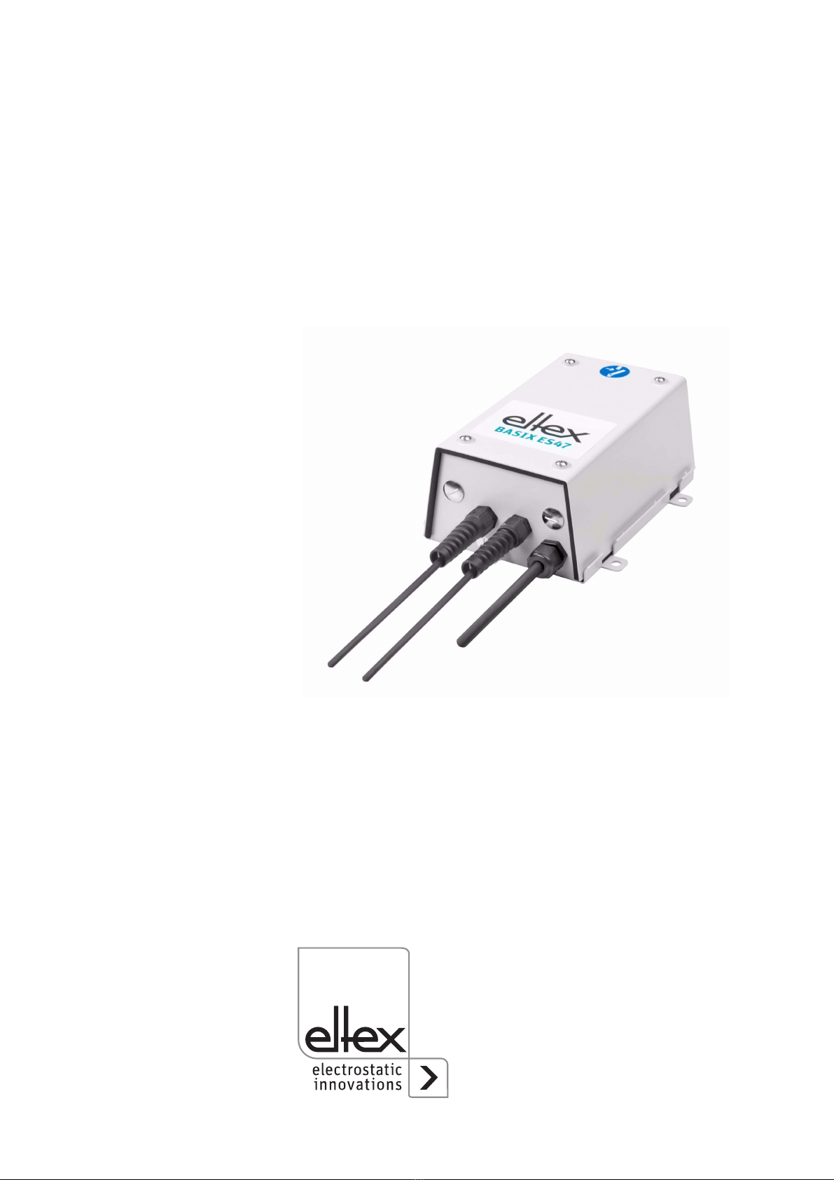
The ES47 high voltage power supplies are power supply units for the
series R47 AC discharging bars, the R36 ion blower nozzles and the ion
blower heads R55.
The discharging bars and the ES47 power supply are used mainly in
cases where disruptive static charges on fast-moving material webs
impair production processes and need to be eliminated.
The ES47 power supply features the following characteristics:
• 4 high voltage outputs
• stable 5 kV AC output voltage
• small dimensions
• easy installation
• stable design in IP54
Please read the operating instructions carefully before starting the instru-
ment. This will help you prevent personal injuries and damage to property.
Please give us a call if you have any suggestions, proposals or ideas for
improvements. We greatly appreciate the feedback from the users of our
appliances.
BA-en-2075-1807_ES47 5
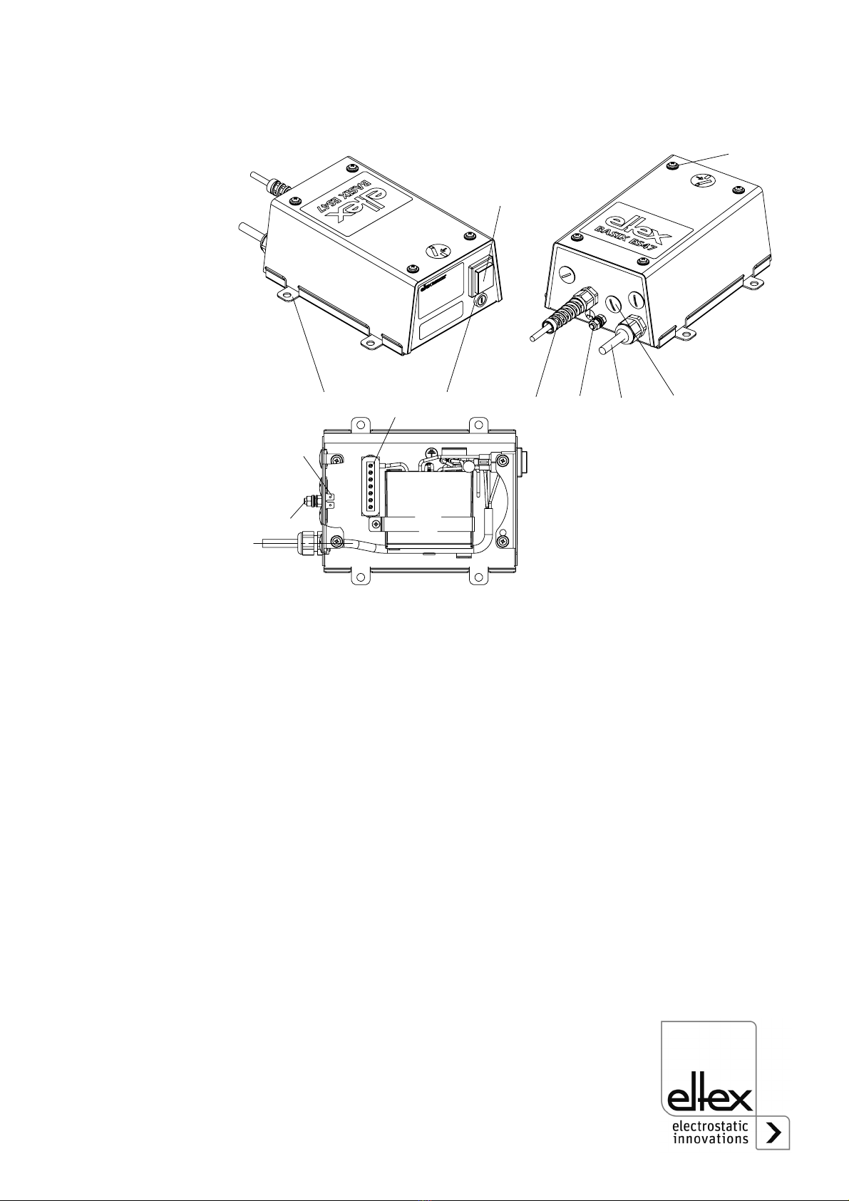
1. Outline of appliance Power Supply ES47
1 ON/OFF switch (ON = lit)
2 Fuse (type: see type plate)
3 High voltage connections (4 pcs.)
3.1 Shown with high voltage plug connected
3.2 Shown as delivered
4 Supply voltage conductor
5 Ground connection
6 Mounting lug
7 Mounting bolts housing cover
X1 Ground connection / protective ground
X2 High voltage base plate
Fig. 1:
ES47 high voltage
power supply for
AC operation
Z-113404by
;
;
;

6BA-en-2075-1807_ES47
2. Safety
The ES47 Power Supplies have been designed, built and tested using
state-of-the-art engineering, and have left the factory in a technically and
operationally safe condition. If used improperly, the units may neverthe-
less be hazardous to personnel and may cause injury or damage. Read
the operating instructions carefully and observe the safety instructions.
Always observe the rules and regulations applying in your country with
reference to opening and repairing electrical appliances.
The manufacturers will not assume any liability and warranty if the units
are used improperly or used outside the intended purpose.
2.1 Proper use
The ES47 Power Supplies may be operated only in connection with the
Eltex R47 discharging bars, the R36 ion blower nozzles and the R55 ion
blower heads for AC operation.
Modifications or changes made to the power supplies are not permitted.
Use only original Eltex spare parts and equipment.
2.2 Identification of risks and hazards
Possible risks and hazards resulting from the use of the power supplies
are referred to in these operating instructions by the following symbols:
Warning!
This symbol appearing in the operating instructions refers to operations
which, if carried out improperly, may result in serious personal injuries.
Caution!
This symbol appearing in the operating instructions refers to operations
which, if carried out improperly, may result in damage to property.
2.3 Work and operational safety
Warning!
Carefully observe the following notes!
• Before starting the unit make sure that the appliance is permanently
grounded via the ground connection (5, Fig. 1). The ground cable
should have a minimum cross section of 1.5 mm2.
• Check the power supplies and the discharging bars at regular intervals
for any damage to the electrical wiring and the high voltage cables. Any
damaged components must be repaired professionally or replaced
before continuing to operate the units.

BA-en-2075-1807_ES47 7
• Before carrying out repairs, cleaning or maintenance work involving the
power supplies and the discharging bars, switch off the power supply
and disconnect the mains power supply.
• Any repair, maintenance or cleaning work must be carried out by quali-
fied personnel.
• If the housing cover is removed, contact protection is no longer effec-
tive. Always disconnect the power before opening the power supply
units.
• The protection class IP 54 only applies if the housing cover is closed
and the cable connections are shrouded.
•Connect/disconnect the discharging bars only if the power supply unit is
switched off and the elctrical supply is disconnected.
• Please note the maximum total lengths of the bars and the high voltage
cables in chapter 3.5.
• Make sure that the bars are clean at all times.
• Wearers of cardiac pacemakers
See separate operating instructions for the bar to be connected.
• The operation of the bars can generate ozone. The ozone concentra-
tion levels developing near the bars depend on many different factors
such as site of installation, bar current and voltage, air circulation, etc.,
and can therefore not be specified in general terms. If the maximum
allowable concentration of ozone must be observed at the site of instal-
lation of the bar, the concentration must be measured on site.
The AGW value (maximum admissible concentration) serves to assess
the ozone concentration at the workplace. The user must make sure
that the appropriate national AGW value is at no times exceeded, e.g.
in Germany the ozone concentration occurring during the operation of
the system must not exceed the recommended value based on interna-
tional limits of 0.06 ml/m³ (0.12 mg/m³).
2.4 Technical advance
The manufacturer reserves the right to make changes to the technical
specifications without prior notice in order to adapt the units to state-of-
the-art engineering. Eltex will provide the latest information on any
changes or modifications in the operating instructions on request.
8BA-en-2075-1807_ES47
3. Installation and assembly
3.1 Assembling the power supply
The power supply is designed for wall mounting. Attach using the brackets
provided (installation dimensions, see Fig. 2). The operating elements of
the power supply and the terminals must be freely accessible at all times.
3.2 Ground connection
A permanent ground connection must be made via the ground connection
(5, Fig. 1). The ground cable should have a minimum cross section of
1.5 mm2.
3.3 Selecting the discharging bars
Eltex R47 discharging bars, R36 ion blower nozzles and R55 ion blower
head for AC operation can be connected to the ES47 power supplies.
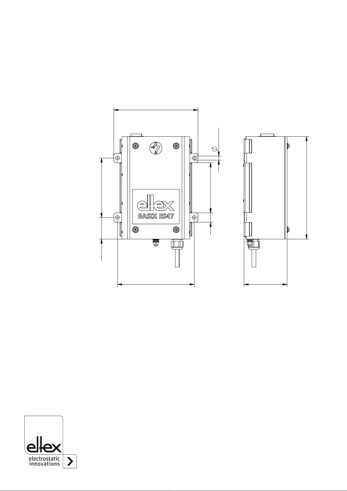
Fig. 2:
Installation dimen-
sions, ES47
Power Supply
Z-113409by
!
[

BA-en-2075-1807_ES47 9
3.4 Connecting the high voltage cable
Warning!
Electric shock hazard!
Connect or disconnect the high voltage cables only with the power supply
switched off!
Connect the discharging bars to the power supply using the prefabricated
high voltage cable.
Method:
• Remove the cover of the power supply (see Fig. 1).
• Remove the nut from the connection at the high voltage cable.
• Insert the connection into the provided opening of the housing.
• Clamp the core of the high voltage cable to the high voltage socket X2.
• Fix the connection inside the unit with the locknut.
•Plug the flat connector of the cable shielding onto ground connection
X1.
Warning!
Terminals at the housing that are not used must be closed with blanking
plugs.
Fig. 3:
High voltage cable
without flexible
tube
Z-114832y_1

10 BA-en-2075-1807_ES47
3.5 Maximum active bar length and length of the high voltage cable
Both the lengths of the high voltage cable and of the active bars are
limited. The shielded high voltage cables cause a capacitive load on the
transformer inside the power supply. The maximum loading capacity is a
result of the function of the total active bar length and the total length of all
high voltage cables. Fig. 4 demonstrates this principle for R47 bars.
Example: The maximum permissible total cable length with a 3 meter
active bar length is 7 meters.
3.6 Connecting the supply voltage
Connect the supply voltage via the power supply lead (4, Fig. 1) using an
earthing pin plug (depending on country).
To ensure that no voltage is supplied to the bars when the material web is
at rest, enabling the supply voltage to the power supply via machine con-
tact is recommended. If the material web is at rest, or if the machine is not
in operation, no high voltage is supplied to the bars in this case.
For external security of the power supply the following circuit breaker is
recommended:
Tripping Characteristic 2A / K according to DIN EN 60947-2.
Fig. 4:
Loading capacity
of the Power
Supply as factor of
bar length and
length of high
voltage cable.
Z01134en
5 10 15
6
4
2
Σlengths of active bars [m]
permissible
range
Σlengths of h.v. cable [m]

BA-en-2075-1807_ES47 11
4. Operation
4.1 Startup
Before starting up the power supply the user must make sure that the
power supply and the bars have been installed and assembled correctly.
The supply voltage can then be switched on.
Use the toggle switch (1, Fig. 1) to switch on the power supply. In the ON
position the switch lights up green. High voltage is now supplied to the dis-
charging bars.
The output voltage is now a constant 5 kV AC.
If the fuse is defective, the switch will not light up.
12 BA-en-2075-1807_ES47
5. Maintenance
Warning!
Electric shock hazard!
Switch the power supply off and disconnect the supply voltage before car-
rying out any maintenance or repair work. The machine in which the dis-
charging bars are installed must not be in operation. Maintenance work
must be carried out by trained or qualified personnel.
Power supply
The power supply must be checked regularly to ensure its proper func-
tioning. The connections of the high voltage cables must be free of dirt
and other foreign matter. The intervals for the check depend on the appli-
cation and must hence be defined by the user according to the operating
conditions. The power supply itself does not require any maintenance.
Check for correct ground connection!
Discharging bars
To ensure the proper function of the discharging bars, clean the bars at
least once a week using compressed air and a brush with soft plastic
bristles. Refer to the operating instructions for the bar used.
Dirt deposits settling on the bars (e.g. grease) must be cleaned off using a
suitable solvent (benzine). Do not soak the bars and the high voltage
cable in solvent!
Caution!
Risk of deflagration!
Allow the solvent to evaporate completely before restarting the unit.
Do not damage the emission tips of the bars.

BA-en-2075-1807_ES47 13
6. Trouble-shooting
Warning!
Electric shock hazard!
Switch the power supply off and disconnect the supply voltage before car-
rying out any maintenance or repair work. Maintenance work must be car-
ried out by trained or qualified personnel.
Fault Cause Measure
No high voltage • Lamp in mains power
switch lit: transformer
defective.
• Lamp in mains power
switch fails to light:
supply voltage not
enabled or not con-
nected.
• Defective fuse.
Inform Eltex Service.
Check supply voltage
and connections. Check
connected cables, cable
connections and bars.
Replace fuse.

14 BA-en-2075-1807_ES47
7. Warranty
The units are warranted for a period of 12 months provided that the opera-
ting conditions have been maintained, that the units have not been tam-
pered with and that the units show no mechanical damage.
The warranty applies only if the operating and assembly instructions spe-
cified by Eltex have been observed. The warranty period begins on the
date of delivery.
In the event of defects occurring during the warranty period, the units or
defective components will be repaired at Eltex. Defective components will
be replaced and installed free of charge.
If repairs are required at the customer's premises, the costs for sending a
technician (travel, travel time, expenses) will be charged to the customer.

BA-en-2075-1807_ES47 15
8. Technical specifications ES47
Supply voltage
Power input
Output voltage
Loading capacity
Output current
Operating ambient
temperature
Storage temperature
Ambient humidity
Mains power cable
Fuse (primary circuit)
Ground connection
High voltage connection
Housing
Protection class
Dimensions
Weight
UL Approval
230 V AC 50/60 Hz; 115 V AC 60 Hz
max. 25 VA
5 kV AC
depending on length of bar and length of high
voltage cable (see 3.5)
max. 2.4 mA at 5 kV
0... +50 °C (+32... +122 °F)
-20... +80 °C (-4... +176 °F)
max. 80% r.h., non-dewing
approx. 2.0 meters with earthing-pin plug,
national version
see name plate
ground connecton on housing
4 pieces
sheet metal steel with wall bracket
IP 54
207 x 170 x 87 mm (H x W x D) (see Fig. 5)
approx. 3.6 kg
File No. E227156
as shown on
appliance
marking:

16 BA-en-2075-1807_ES47
9. Dimensions
Fig. 5:
Dimensions, ES47
Power Supply
Z-113409by
!
[
BA-en-2075-1807_ES47 17
10. Spare parts and accessories
Please specify the article number when ordering.
Article Article No.
High voltage cable without flexible tube from
power supply ES47 to blower nozzle R36
resp. blower head R55 (specify cable length)
Plug "X"
Kit for cutting high voltage cable to size
without flexible tube for bar R47
Hexagonal crimper, 5.41 mm
Blanking plug, M16 x 1.5
Nut, M16 x 1.5
Mains cable gland
Fuse F1 (115 V) 0.315 A T (IEC 60127-2/3)
Fuse F1 (230 V) 0.63 A T (IEC 60127-2/3)
Accessory
Kit of fixing screws and cover
Operating instructions (specify language)
KE/Xy
113259
102952
113399
104974
MCH02176
ELM00722
105659
113402
115795
BA-xx-2075

18 BA-en-2075-1807_ES47


Eltex-Elektrostatik-Gesellschaft mbH
Blauenstraße 67-69, D-79576 Weil am Rhein
Phone +49 (0) 76 21/ 79 05 - 230
Fax +49 (0) 76 21/ 79 05 - 330
eMail static-con[email protected]
Internet www.eltex.com
Eltex offices
and agencies
The addresses of all
Eltex agencies can be
found on our website at
www.eltex.com
Z01007y
Table of contents
Other ELTEX Power Supply manuals


Popular Power Supply manuals by other brands


cytiva
cytiva EPS 3501 XL operating instructions

Diablotek
Diablotek MICRO ATX/ATX POWER SUPPLY user manual

Powerware
Powerware 5075 kVA Installation & operation manual

twintex
twintex TFC6000 Series Operation manual

Genetec
Genetec SY-SIX-PSU-DIN-8A installation manual

Matsusada
Matsusada DOEF Series instruction manual