ELTEX ES24 Series User manual

Operating Instructions
Compact Power 24 V
Series ES24 Power Supplies
for supplying AC discharging bars
BA-en-2062-2106
F01063y

2BA-en-2062-2106_ES24

BA-en-2062-2106_ES24 3
List of contents
1 Outline of appliance ES24 power supply . . . . . . . . . . . . . . . . . 6
2 Safety . . . . . . . . . . . . . . . . . . . . . . . . . . . . . . . . . . . . . . . . . . . . . . 7
2.1 Proper use . . . . . . . . . . . . . . . . . . . . . . . . . . . . . . . . . . . . . . . . . . . 7
2.2 Identification of risks and hazards . . . . . . . . . . . . . . . . . . . . . . . . . 7
2.3 Work and operational safety . . . . . . . . . . . . . . . . . . . . . . . . . . . . . 7
2.4 Technical advance . . . . . . . . . . . . . . . . . . . . . . . . . . . . . . . . . . . . . 9
3 Installation and assembly . . . . . . . . . . . . . . . . . . . . . . . . . . . . . 10
3.1 Assembly the power supply . . . . . . . . . . . . . . . . . . . . . . . . . . . . . 10
3.2 Ground connection . . . . . . . . . . . . . . . . . . . . . . . . . . . . . . . . . . . 12
3.3 Connecting the high voltage cable . . . . . . . . . . . . . . . . . . . . . . . . 12
3.4 Dismantling / Assembling the plug housing . . . . . . . . . . . . . . . . . 13
3.5 Maximum active bar length and length of the high
voltage cable . . . . . . . . . . . . . . . . . . . . . . . . . . . . . . . . . . . . . . . . 14
3.6 Connecting supply voltage and fault signal contact . . . . . . . . . . . 15
4 Operation . . . . . . . . . . . . . . . . . . . . . . . . . . . . . . . . . . . . . . . . . . 16
4.1 Startup . . . . . . . . . . . . . . . . . . . . . . . . . . . . . . . . . . . . . . . . . . . . . 16
4.2 Function monitoring . . . . . . . . . . . . . . . . . . . . . . . . . . . . . . . . . . . 16
5 Maintenance . . . . . . . . . . . . . . . . . . . . . . . . . . . . . . . . . . . . . . . . 17
5.1 Power Supply . . . . . . . . . . . . . . . . . . . . . . . . . . . . . . . . . . . . . . . . 17
5.2 Discharging bars. . . . . . . . . . . . . . . . . . . . . . . . . . . . . . . . . . . . . . 17
6 Trouble shooting . . . . . . . . . . . . . . . . . . . . . . . . . . . . . . . . . . . . 18
7 Warranty . . . . . . . . . . . . . . . . . . . . . . . . . . . . . . . . . . . . . . . . . . . 19
8 Technical specifications ES24 . . . . . . . . . . . . . . . . . . . . . . . . 20
9 Dimensions . . . . . . . . . . . . . . . . . . . . . . . . . . . . . . . . . . . . . . . . 21
10 Spare parts and accessories . . . . . . . . . . . . . . . . . . . . . . . . . . 22
Declaration of Conformity . . . . . . . . . . . . . . . . . . . . . . . . . . . . . . . . . . 23

4BA-en-2062-2106_ES24

BA-en-2062-2106_ES24 5
Dear Customer,
The ES24 high voltage power supplies are power supply units for the ion
blower nozzles, ion blower heads and the series R45, R47, R5x and R6x
AC discharging bars.
The discharging bars and the ES24 power supply are used mainly in
cases where disruptive static charges on fast-moving material webs
impair production processes and need to be eliminated.
The ES24 power supply features the following characteristics:
• stable 5 kV AC output voltage
• output current monitoring
• short-circuit proof
• independent from different national line voltages
• connecting options for several consumer units
(bars, blowing nozzles) via ESVY61 or ESV61 high voltage distributor
(optional)
• protection class IP54
• compact design, small dimensions
• adaptable and easy to install
• low weight compared with conventional transformers
Please read the operating instructions carefully before starting the instru-
ment. This will help you prevent personal injuries and damage to property.
Please give us a call if you have any suggestions, proposals or ideas for
improvements. We greatly appreciate the feedback from the users of our
appliances.

6BA-en-2062-2106_ES24
1. Outline of appliance ES24 power supply
1 Universal plug: supply voltage and potential-free contact
Pin 1: potential-free fault signal contact
Pin 2: 24 V DC
Pin 3: GND
Pin 4: potential-free fault signal contact;
trouble-free state - contact closed
2 Operational grounding connection
3 LED status; function and error messages display
4 Fixing holes for scews M5
5 2 high voltage outputs: connection of the consumer units
(discharging bars, high voltage distributor ESVY61 / ESV61)
Fig. 1:
ES24/O high vol-
tage power supply
for AC operation
Z-113416by_2
BA-en-2062-2106_ES24 7
2. Safety
The ES24 Power Supplies have been designed, built and tested using
state-of-the-art engineering, and have left the factory in a technically and
operationally safe condition. If used improperly, the units may neverthe-
less be hazardous to personnel and may cause injury or damage. Read
the operating instructions carefully and observe the safety instructions.
Always observe the rules and regulations applying in your country with
reference to opening and repairing electrical appliances.
The manufacturers will not assume any liability and warranty if the units
are used improperly or used outside the intended purpose.
2.1 Proper use
The ES24 Power Supplies may be operated only in connection with the
appropriate Eltex discharging bars for AC operation.
Modifications or changes made to the power supplies are not permitted.
Use only original Eltex spare parts and equipment.
2.2 Identification of risks and hazards
Possible risks and hazards resulting from the use of the power supplies
are referred to in these operating instructions by the following symbols:
Warning!
This symbol appearing in the operating instructions refers to operations
which, if carried out improperly, may result in serious personal injuries.
Caution!
This symbol appearing in the operating instructions refers to operations
which, if carried out improperly, may result in damage to property.
2.3 Work and operational safety
Warning!
Carefully observe the following notes and the complete chapter 2 "Safety”,
page 7!
• Before carrying out repairs, cleaning or maintenance work and before
resetting after malfunctions, switch off the power supply and disconnect
the mains supply voltage (see chapter 5 "Maintenance”, page 17, chap-
ter 6 "Troubleshooting”, page 18).
• Before carrying out any work involving the units, the machine which has
the units fitted must not be in operation (see chapter 5 "Maintenance”,
page 17, chapter 6 "Troubleshooting”, page 18).

8BA-en-2062-2106_ES24
• Any work involving the units must be carried out by qualified electrici-
ans (see chapter 5 "Maintenance”, page 17, chapter 6 "Troubleshoo-
ting”, page 18).
• The ES24 high voltage power supply must be operated only with a
24 VDC line voltage (see chapter 4 "Operation”, page 16).
• Before starting up the power supply the user must make sure that the
power supply and the bars have been installed and assembled
correctly. The supply voltage can then be switched on (see chapter 4
"Operation”, page 16).
• Before starting the unit make sure that the appliance is permanently
grounded via the grounding terminal (2, Fig. 1). The ground cable
should have a minimum cross section of 1.5 mm2(see chapter 3.2
"Ground connection”, page 12).
• Check the units, the electrical wiring and the hight voltage cable at
regular intervals and before startup for any damage. Any damaged
components must be repaired profesionally or replaced before conti-
nuing to operate the units, or the bar or cable must be disabled.
• Connect or disconnect the high voltage cable / the bars only with the
power supply switched off (see chapter 3.3 "Connecting the high vol-
tage cable”, page 12).
• In applications involving moving bar, the high voltage cable must be
attached such that there is no cable movement near the connection
zone of the consumer units (power supply, distributer or discharging
bar); see chapter 3.3 "Connecting the high voltage cable”, page 12).
• Both the lengths of the high voltage cable and of the active bars are
limited, observe maximum lengths (see chapter 3.5 "Maximum active
bar length and length of the high voltage cable”, page 14).
• Operating the ES24 power supply requires a 24 V DC line voltage
designed for a maximum current of 1.4 A (see chapter 3.6 "Connecting
supply voltage and fault signal contact”, page 15).
• The supply voltage 24 V DC at the universal plug must be connected to
Contact 2 (24 V) and Contact 3 (Ground), or plugged into the power
supply available as accessory.
Contact 3 (Ground) must be connected to the ground (see chapter 3.6
"Connecting supply voltage and fault signal contact”, page 15).
• Make sure that the units are clean at all times.
Dirt results in malfunctions and in premature wear of the units.
• The power supply must be checked regularly to ensure its proper func-
tioning. The connections of the high voltage cables must be free of dirt
and other foreign matter. Check for correct ground connection (see
chapter 5 "Maintenance”, page 17).

BA-en-2062-2106_ES24 9
• When cleaning do not soak the bars and the high voltage cable in sol-
vent and do not damage the emission tips; allow the solvent to evapo-
rate completely before restarting the unit (see chapter 5 "Maintenance”,
page 17).
• Wearers of cardiac pacemakers:
See separate operating instructions for the bar to be connected.
• The operation of the bars can generate ozone. The ozone concentra-
tion levels developing near the bars depend on many different factors
such as site of installation, bar current and voltage, air circulation, etc.
and can therefore not be specified in general terms.
If the maximum allowable concentration of ozone must be observed at
the site of installation of the bar, the concentration must be measured
on site.
The AGW value (maximum admissible concentration) serves to assess
the ozone concentration at the workplace. The user must make sure
that the appropriate national AGW value is at no times exceeded, e.g.
in Germany the ozone concentration occurring during the operation of
the system must not exceed the recommended value based on interna-
tional limits of 0.06 ml/m³ (0.12 mg/m³).
2.4 Technical advance
The manufacturer reserves the right to make changes to the technical
specifications without prior notice in order to adapt the units to state-of-
the-art engineering. Eltex will provide the latest information on any chan-
ges or modifications in the operating instructions on request.

10 BA-en-2062-2106_ES24
3. Installation and assembly
3.1 Assembly the power supply
The power supply is designed for wall mounting. Attach using the brackets
provided (installation dimensions, see Fig. 2). The terminals of the power
supply must be freely accessible at all times and the display LEDs must
be visible.
Fig. 2:
Installation dimen-
sions, ES24/O
Power Supply
Z113417ay_2
Y

BA-en-2062-2106_ES24 11
Installation examples
When connecting several consumer units (bars, ion blower nozzles and
heads) using an ESVY61 / ESV61 high voltage distributor, the entire
active bar and cable length must be within the permissible range of the
loading capacity diagram (Fig. 7, Fig. 8).
Fig. 3:
Installation
examples
Z-113171ay_1
Fig. 4:
Installation
examples
Z-113171ay_2
Example:
connection of several
consumer units via a
high voltage distributor
12 BA-en-2062-2106_ES24
3.2 Ground connection
A permanent grounding connection must be made and checked via the
ground terminal (2, Fig. 1) and routed with the shortest possible distance
to the machine frame. The ground cable should have a minimum cross
section of 1.5 mm2.
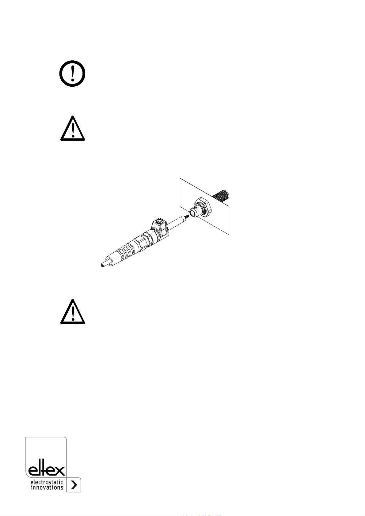
3.3 Connecting the high voltage cable
Warning!
Connect or disconnect the high voltage cable only with the power supply
switched off!
Connect the discharging bars to the power supply using the prefabricated
high voltage cable. Push the high voltage cables into the sockets up to the
stop. Make sure that the locking pin is fully engaged.
To pull out the high voltage plug, use a flat screwdriver to lift the locking
pin.
Warning!
In applications involving moving bar, the high voltage cable must be
attached such that there is no cable movement near the connection zone
of the consumer units (power supply, distributer or discharging bar).
Fig. 5:
Connecting the
high voltage cable
Z-112068y
BA-en-2062-2106_ES24 13
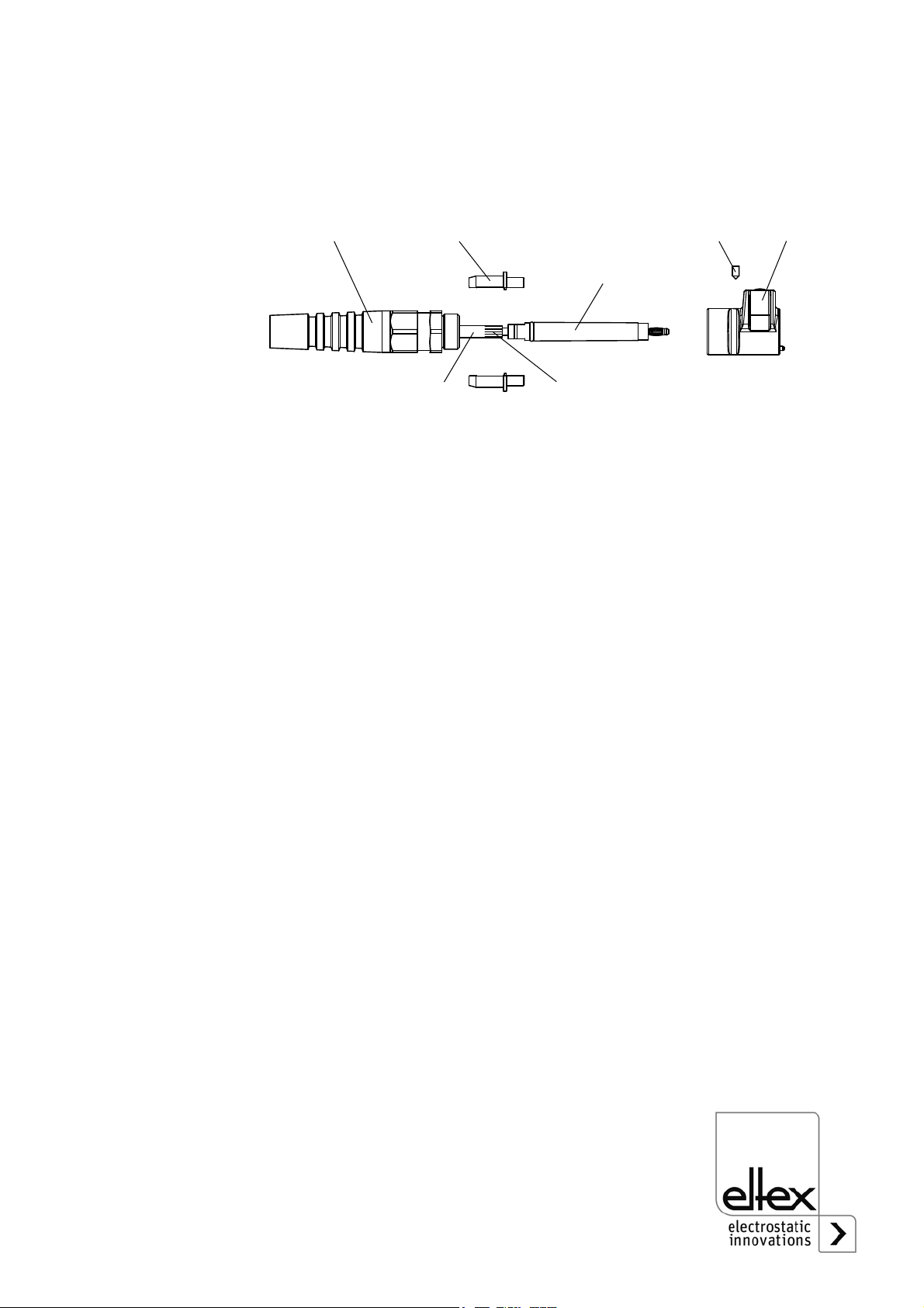
3.4 Dismantling / Assembling the plug housing
To route the cable through a wall or a grommet, the plug housing and the
threaded anti-kink joint can be dismantled and removed.
• First loosen the union nut of the threaded anti-kink joint (1).
• Turn the threaded anti-kink joint (1) out of the plug housing (7).
• Loosen the grub screw (6) located immediately behind the locking pin.
• Fix both semi-shells (4) of the shield carrier in place and pull the plug
housing (7) off to the front. Then remove the two semi-shells (4).
• The jack (5) with the split-pin plug is encapsulated with the high-voltage
cable (2) and cannot be dismantled.
• If required, widen the sealing rubber of the threaded anti-kink joint and
pull the threaded ant-kink joint (1) off over the jack.
• To assemble, proceed in reverse order. When replacing the semi-
shells, make sure that the shield (3) is properly tucked over and that the
whole unit is properly and correctly assembled.
Fig. 6:
Dismantling /
Assembling
the plug housing
Z-112070ay_2

14 BA-en-2062-2106_ES24
3.5 Maximum active bar length and length of the high
voltage cable
Both the lengths of the high voltage cable and of the active bars are
limited. The shielded high voltage cables cause a capacitive load on the
transformer inside the power supply. The maximum loading capacity is a
result of the function of the total active bars length and the total length of
all high voltage cables. Fig. 7 demonstrates this principle for R45 / R50
bars and Fig. 8 for R47 / R60 bars.
When connecting several consumer units (bars, ion blower nozzles and
heads) using an ESVY61 / ESV61 high voltage distributor, the entire
active bar and cable length must be within the permissible range of the
loading capacity diagram (Fig. 7 / Fig. 8).
Fig. 7:
Loading capacity
of the power sup-
ply as factor of
R45 / R50 active
bar length and
length of high
voltage cable
Example:
The maximum permissible total
cable length with a 1 meter active
bar length is 4,1 meters.
Z01132en
Σlengths of h.v. cable [m]
Σlenghts of active bars [m]
3
2
1
0.7 2 4 6
permissible
range
Fig. 8:
Loading capacity
of the power sup-
ply as factor of
R47 / R60 active
bar length and
length of high
voltage cable
Z01165e
lengths of h.v. cable [m]
lengths of active bars [m]
2,0
1,0
0,7 2 4 6
permissible
range
BA-en-2062-2106_ES24 15
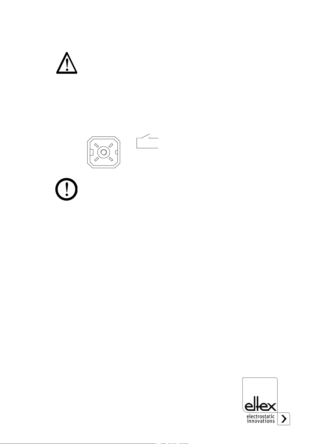
3.6 Connecting supply voltage and fault signal contact
Operating the ES24 power supply requires a 24 V DC line voltage
designed for a maximum current of 1.4 A.
The supply voltage is provided by the customer and is connected via the
connector supplied. The power supply available as accessory may be
used as an alternative.
To ensure that no high voltage applies at the bars when the web is at rest,
we recommend to switch off the supply voltage of the units. If the web is at
rest or if the machine is not in operation, no high voltage applies at the
bars.
Caution!
The supply voltage 24 V DC at the universal plug must be connected to
Contact 2 (24 V) and Contact 3 (Ground), or plugged into the power
supply available as accessory.
Contact 3 (Ground) must be connected to the ground.
If required, a potential-free fault signal contact (max. contact load 24 A /
0.5 A DC) may be tapped from Contact 1 (COM) and Contact 4:
• trouble-free state: contact closed
• Fault: contact open
• No line voltage: contact open
If the optional power supply is used, the use of the fault signal contact is
not envisaged.
Fig. 9:
Universal plug
Z-113418y
&20
9'&
9*1'

16 BA-en-2062-2106_ES24
4. Operation
The ES24 high voltage power supply must be operated only with a
24 VDC line voltage.
4.1 Startup
Before starting up the power supply the user must make sure that the
power supply and the bars have been installed and assembled
correctly. The supply voltage can then be switched on.
4.2 Function monitoring
Two LEDs in the connection zone signal the proper function of the unit.
• The device version ES24/O hast two LEDs (green, red) and device
version ES24/C has three LEDs (green, yellow, red).
• If none of the two LEDs is lit, the supply voltage is not switched on.
• When the bar starts, all two (green, red) must light up briefly.
Note!
Faults will not be saved. A disruption of the supply voltage automatically
results in the fault message being acknowledged.
Green LED Red LED
Operations status of the
output voltage Error status
LED on High voltage in ON. Internal error
LED off High voltage is OFF. No error
LED flashes The ES24 power supply
operates at its capacity limit.
High voltage error

BA-en-2062-2106_ES24 17
5. Maintenance
Warning!
Electric shock hazard!
• Switch off the power supply unit and disconnect the supply voltage
before carrying out any maintenance or repair work.
• The machine which has the units fitted must not be in operation.
• Repairs and maintenance work must be carried out by qualified
electricians.
5.1 Power supply
The power supply must be checked regularly to ensure its proper func-
tioning. The connections of the high voltage cables must be free of dirt
and other foreign matter. The intervals for the check depend on the appli-
cation and must hence be defined by the user according to the operating
conditions. The power supply itself does not require any maintenance.
Check for correct ground connection!
5.2 Discharging bars
To ensure the proper function of the discharging bars, clean the bars at
least once a week using compressed air (max. 6 x 10⁵ Pa) and a brush
with soft plastic bristles. Refer to the operating instructions for the bar
used.
Dirt deposits settling on the bars (e.g. grease) must be cleaned off using a
suitable solvent (cleaning gasoline). Do not soak the bars and the high
voltage cable in solvent!
Caution!
Risk of deflagration!
Allow the solvent to evaporate completely before restarting the unit.
Do not damage the emission tips of the bars.

18 BA-en-2062-2106_ES24
6. Troubleshooting
Warning!
Electric shock hazard!
• Switch off the power supply unit and disconnect the supply voltage
before carrying out any maintenance or repair work.
• The machine which has the units fitted must not be in operation.
• Repairs and maintenance work must be carried out by qualified
electricians.
Failure Cause Measure
No LED
lights up.
No supply voltage. Check supply voltage and
connections.
Inform Eltex Service.
Green LED
flashes.
The power supply
operates at the limit of
its capacity.
Check the maximum permissible
bar and/or cable length. Clean
the discharging bars. Check the
high voltage cable or the dis-
charging bars for any damage.
Red LED
lights up.
Internal error. To acknowledge the fault, switch
the supply voltage off and back
on. If the fault persists, notify
Eltex Service.
Red LED
flashes.
• Short circuit at the
high voltage out-
put.
• No output voltage.
• Check the maximum permis-
sible bar / cable length.
Clean the discharging bars.
Check the high voltage cable
/ the discharging bars for any
damage.
• Inform Eltex Service.

BA-en-2062-2106_ES24 19
7. Warranty
The units are warranted for a period of 12 months provided that the opera-
ting conditions have been maintained, that the units have not been tam-
pered with and that the units show no mechanical damage.
The warranty applies only if the operating and assembly instructions spe-
cified by Eltex have been observed. The warranty period begins on the
date of delivery.
In the event of defects occurring during the warranty period, the units or
defective components will be repaired at Eltex. Defective components will
be replaced and installed free of charge.
If repairs are required at the customer's premises, the costs for sending a
technician (travel, travel time, expenses) will be charged to the customer.

20 BA-en-2062-2106_ES24
8. Technical specifications ES24
Supply voltage
Power input
Output voltage
Loading capacity
Output current
Ambient operating
temperature
Storage temperature
Ambient humidity
Optical indicator
Mains power
Ground link
High voltage connection
High voltage distributor
ESVY61 (optional)
High voltage distributor
ESV61 (optional)
Enclosure
Protection class
Dimensions
Weight
UL Approval
24 V DC +/- 10 %
15 VA max.
5 kV AC / 100 Hz
depending on bar length and length of high
voltage cable (see chapter 3.5)
max. 2.0 mA at 5 kV
0 °C...+40°C (+32°F...+104°F)
0 °C...+70°C (+32°F...+158°F)
max. 80% r.h., non-dewing
LED on housing:
green: high voltage active
red: malfunction
socket contact with plug,
power supply as optional accessory
grounding terminal on housing
2 plug-type high voltage connection
2 plug-type high voltage connections
(1 high voltage cable, 2 outputs)
4 plug-type high voltage connections
(1 high voltage cable, 4 outputs)
plastic with wall-mounted bracket
P54 according to EN 60529
60 x 155 x 90 mm (H x W x D)
(see Fig. 10)
approx. 1.1 kg
File No. E227156
as shown on
appliance
marking:
Table of contents
Other ELTEX Power Supply manuals


