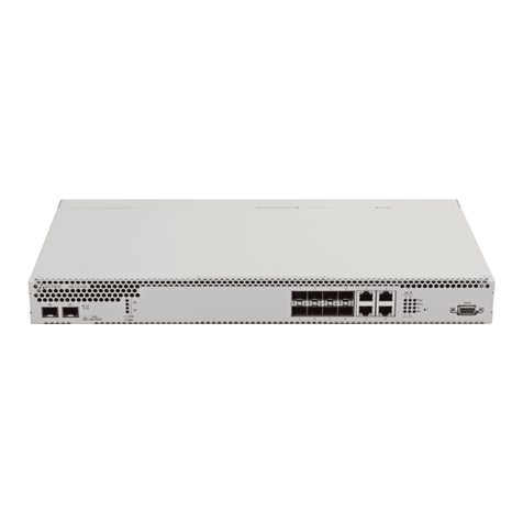
ELTEX MES1000 User manual

L2 Fast Ethernet and Gigabit Ethernet Managed Switches
MES1000, MES2000
Operation Manual,Firmware Version 1.1.42

2MES1000, MES2000 Ethernet Switches
Document version
Issue date
Revisions
Version 2.17
20/10/2015
Changes in chapters:
- 5.23.1 Copper-wire cable diagnostics
Version 2.16
31/08/2015
Added description of MES1124MB, MES1124M DC, MES2124M DC
Changes in chapters:
- 2.2.8 Additional functions
- 2.3 Main specifications
- 2.4 Design
- 5.5 System management commands
- 5.10 Interface configuration
- 5.11 Selective Q-in-Q
- 5.12 Broadcast storm control
- 5.13 Link Agregation Group (LAG)
- 5.16.6 Flex-link function configuration
- 5.19.1 ААА mechanism
- 5.21 Port mirroring (monitoring)
- 5.33.1 QoS Configuration
Added chapters:
- 5.24 IP Service Level Agreements (IP SLA)
Version 2.15
18/05/2015
Added description of MES1124M, MES2124M.
Added chapters:
- 2.4.3 MES1124M, MES2124M series devices panels appearance and
layout
- 5.28 DHCP protocol management and Option 82
Changes in chapters:
- 2.2.7 Switch control function
- 2.3 Main specifications
- 5.5 System management commands
- 5.8.1 Command parameters description
- 5.8.3 Configuration backup commands
- 5.10.1 Ethernet and Port-Channel interface parameters
- 5.10.2 VLAN interface configuration
- 5.16.4 Loopback detection mechanism
- 5.16.5 STP protocol family (STP, RSTP, MSTP)
- 5.16.6 Flex-link function configuration
- 5.16.11 CFM protocol configuration
- 5.19.2 RADIUS protocol
- 5.19.4 Simple network management protocol (SNMP)
- 5.26.2.2 Advanced authentication
- 5.26.3 DHCP protocol management and Options 82
- 5.27 DHCP Relay mediations features
Version 2.14
17/02/2015
Added chapters:
- 3.3 SFP transceiver installation and removal
Changes in chapters:
- 5.10.2 VLAN interface configuration
- 5.12 Broadcast storm control
- 5.18.2 IGMP snooping function
- 5.19.4 Simple network management protocol (SNMP)
- 5.26.2.2 Advanced authentication
Version 2.13
14/01/2015
Changes in chapters:
- 5.8.3 Configuration backup commands
Added chapters:
- 5.15.3 IPv6 ra guard function configuration
- 5.15.4 DHCPv6 guard function configuration
- 5.16.6 Flex-link function configuration
Version 2.12
21/10/2014
Synchronized with firmware version 1.1.30.
Changes in chapters:
- 5.10.2 VLAN interface configuration
- 5.12 Broadcast storm control
Version 2.11
27/08/2014
Changes in chapters:
- 5.10 Interface configuration
- 5.16.6 EAPS protocol
- 5.27 DHCP Relay mediation features

MES1000, MES2000 Ethernet Switches 3
Version 2.10
28/07/2014
Changes in chapters:
- 5.19.7.1 Telnet, SSH, HTTP and FTP
Version 2.9
12/05/2014
Added description of devices MES2124P, MES2208P
Version 2.8
06/05/2014
Changes in chapters:
- 5.5 System management commands
- 5.19.2 IGMP Snooping function
Version 2.7
27/03/2014
Changes in chapters:
5.24.1 Copper-wire cable diagnostics
5.25.6 DHCP protocol management and Option 82
Version 2.6
09/01/2014
Changes in chapters:
- 5.18.2 IGMP Snooping function
- 5.18.4 Multicast traffic restriction functions
Added chapters:
- 4.3 Configuration procedure
- 5.18.5 RADIUS Authorization of IGMP Queries
- Configuration of IGMP Query Authorization via RADIUS (appendix А)
Version 2.5
22/11/2013
Changes in chapters:
- 5.16.5 STP protocol family (STP, RSTP, MSTP)
- 5.9.1 Ethernet and Port-Channel interface parameters
- 5.16.6 EAPS protocol
- 5.19.2 Radius protocol
Added chapters:
- 5.3 Filtering of command line messages
Version 2.4
15/08/2013
Changes in chapters:
- 5.26.1 IPv4 ACL Configuration
- 5.26.2 IPv6 ACL Configuration
- 5.26.3 MAC ACL Configuration
Version 2.3
05/07/2013
Added chapters:
- 6.27 Configuration of Protection from DoS Attacks
Changes in chapters:
- Appendix АSamples of use and configuration of device
Version 2.2
18/06/2013
Added chapters:
- 5.14.9 OAM protocol configuration
- 5.14.10 CFM protocol configuration
Changes in chapters:
- 4.1 Terminal configuration
- 5.9 Broadcast storm control
- 5.17.1 ААА mechanism
- 5.17.7.1Telnet, SSH, HTTP and FTP
- 5.17.7.2 Terminal configuration commands
Version 2.1
28/05/2013
Added chapters:
- 5.6.3 Configuration backup commands
- 5.15.7 G.8032v2 (ERPS) protocol configuration
Changes in chapters:
- 5.18.2 RADIUS protocol
- 5.18.3 TACACS+ protocol
- 5.18.4 SNMP network management protocol
- 5.21.2 Optical transceiver diagnostics
Version 2.0
03/04/2013
Added description of the device MES1124
Version 1.6
20/03/2013
Added chapters:
- Multicast traffic restriction features
Changes in chapters:
- IGMP snooping funcion
- ААА mechanism
- Access configuration
- DHCP protocol management and Option 82
- PPPoE Intermediate Agent configuration
Version 1.5
06/03/2013
Changes in chapters:
- 5.4 System management commands;
- 5.9 Selective Q-in-Q;
- 5.17.2 IGMP Snooping function
Added chapters:
- Appendix B Typical buildings of networks on basis of EAPS protocol

4MES1000, MES2000 Ethernet Switches
Version 1.4
28/12/2012
Changes in chapters:
- 5.4 Added description of the CPU monitoring and protection feature
configuration.
- 5.8.1. Added description of the interface load monitoring feature
configuration.
- 5.8.2. Added description of MAC-based vlan, EtherType configuration
for outgoing packets.
- 5.17.1. Added description of MAC address learning configuration in
VLAN.
- 5.18.4. Added description of SNMP trap messages configuration on
ports.
- 5.20. Added description of remote mirroring configuration.
- 5.23.3. Added description of DHCP Option 82 format configuration.
Added chapters:
-5.23.6 MAC Address Notification function configuration.
Version 1.3
10/09/2012
Changes in chapters:
5.22 Physical diagnostics functions
Version 1.2
21/08/2012
Added description of EAPS protocol configuration.
Version 1.1
12/05/2012
Added chapters:
- PPPoE Intermediate Agent configuration
Version 1.0
21/12/2011
First issue.
Firmware version
1.1.42

MES1000, MES2000 Ethernet Switches 5
CONTENTS
1 INTRODUCTION ...........................................................................................................................................9
2 PRODUCT DESCRIPTION ............................................................................................................................10
2.1 Purpose..............................................................................................................................................10
2.2 Device Functions...............................................................................................................................10
2.2.1 Basic functions.........................................................................................................................10
2.2.2 MAC Address Processing Functions.........................................................................................11
2.2.3 Second-layer functions of OSI model ......................................................................................11
2.2.4 Third-layer functions of OSI model..........................................................................................13
2.2.5 QoS functions...........................................................................................................................13
2.2.6 Security functions ....................................................................................................................13
2.2.7 Switch control functions..........................................................................................................14
2.2.8 Additional functions.................................................................................................................15
2.3 Main specifications............................................................................................................................16
2.4 Design ................................................................................................................................................19
2.4.1 MES1024, MES1124, MES2124 series devices front panel appearance and layout ...............19
2.4.2 MES1124MB, MES2124MB series devices panels appearance and layout .............................20
2.4.3 MES1124M, MES2124M series devices panels appearance and layout .................................22
2.4.4 MES2208P series device panel appearance and layout ..........................................................24
2.4.5 MES2124P series device panel appearance and layout ..........................................................25
2.4.6 Side panels of the device .........................................................................................................26
2.4.7 Light Indication ........................................................................................................................26
2.5 Delivery Package................................................................................................................................28
3 INSTALLATION AND CONNECTION............................................................................................................29
3.1 Support brackets mounting...............................................................................................................29
3.2 Device rack installation......................................................................................................................29
3.3 Battery connection to MES1124MB, MES2124MB ...........................................................................31
3.4 SFP transceiver installation and removal ..........................................................................................31
3.5 Connection to Power Supply .............................................................................................................32
4 DEVICE STARTUP, INITIAL CONFIGURATION .............................................................................................33
4.1 Configuring the Terminal...................................................................................................................33
4.2 Turning off the device .......................................................................................................................33
4.3 Configuration procedure ...................................................................................................................35
4.3.1 Stackable Mode Selection........................................................................................................35
4.3.2 Initial Configuration .................................................................................................................36
4.3.3 Security system configuration .................................................................................................39
5 DEVICE MANAGEMENT COMMAND LINE INTERFACE ..............................................................................42
5.1 Command Line Operation Principles.................................................................................................43
5.2 Basic commands ................................................................................................................................43
5.3 Filtering of command line messages .................................................................................................45
5.4 Macrocommand configuration..........................................................................................................45
5.5 System management commands ......................................................................................................46
5.6 Switch Stack Management ................................................................................................................50
5.7 Commands for configuration of password parameters ....................................................................52
5.8 File operations...................................................................................................................................53
5.8.1 Command parameters description..........................................................................................53
5.8.2 File operation commands ........................................................................................................53
5.8.3 Configuration backup commands............................................................................................55
5.8.4 Automatic update and configuration commands....................................................................56
5.9 System time configuration ................................................................................................................58
5.10 Interface configuration......................................................................................................................61
5.10.1 Ethernet and Port-Channel interface parameters................................................................62
5.10.2 VLAN interface configuration ...............................................................................................69

6MES1000, MES2000 Ethernet Switches
5.11 Selective Q-in-Q ................................................................................................................................ 75
5.12 Broadcast storm control ................................................................................................................... 76
5.13 Link Aggregation Groups (LAG)......................................................................................................... 77
5.13.1 Static link aggregation groups.............................................................................................. 78
5.13.2 LACP link aggregation protocol............................................................................................ 79
5.14 IPv4 addressing configuration .......................................................................................................... 80
5.15 IPv6 addressing configuration .......................................................................................................... 81
5.15.1 IPv6 protocol........................................................................................................................ 81
5.15.2 IPv6 protocol tunnelling (ISATAP)........................................................................................ 84
5.15.3 IPv6 RA guard function configuration.................................................................................. 86
5.15.4 DHCPv6 guard function configuration ................................................................................. 87
5.16 Protocol configuration...................................................................................................................... 88
5.16.1 DNS protocol configuration—domain name system........................................................... 88
5.16.2 ARP protocol configuration.................................................................................................. 89
5.16.3 GVRP protocol configuration ............................................................................................... 90
5.16.4 Loopback detection mechanism (loopback-detection) ....................................................... 92
5.16.5 STP protocol family (STP, RSTP, MSTP)................................................................................ 93
5.16.6 Flex-link function configuration........................................................................................... 99
5.16.7 EAPS protocol..................................................................................................................... 100
5.16.8 G.8032v2 (ERPS) protocol configuration ........................................................................... 101
5.16.9 LLDP protocol configuration .............................................................................................. 103
5.16.10OAM protocol configuration.............................................................................................. 108
5.16.11CFM protocol configuration............................................................................................... 110
5.17 Voice VLAN...................................................................................................................................... 113
5.18 Multicast addressing....................................................................................................................... 115
5.18.1 Multicast addressing rules................................................................................................. 115
5.18.2 IGMP snooping function .................................................................................................... 120
5.18.3 MLD snooping—multicast traffic control protocol for IPv6 networks .............................. 124
5.18.4 Multicast traffic restriction functions................................................................................ 126
5.18.5 RADIUS Authorization of IGMP Queries ............................................................................ 127
5.19 Control functions ............................................................................................................................ 129
5.19.1 AAA mechanism................................................................................................................. 129
5.19.2 RADIUS protocol ................................................................................................................ 133
5.19.3 TACACS+ protocol .............................................................................................................. 135
5.19.4 Simple network management protocol (SNMP)................................................................ 136
5.19.5 Remote network monitoring protocol (RMON) ................................................................ 140
5.19.6 ACL access lists for device management ........................................................................... 146
5.19.7 Access configuration.......................................................................................................... 147
5.20 Alarm log, SYSLOG protocol............................................................................................................ 151
5.21 Port mirroring (monitoring)............................................................................................................ 153
5.22 sFlow function................................................................................................................................. 155
5.23 Physical layer diagnostics functions ............................................................................................... 156
5.23.1 Copper-wire cable diagnostics........................................................................................... 156
5.23.2 Optical transceiver diagnostics .......................................................................................... 158
5.24 IP Service Level Agreements (IP SLA).............................................................................................. 160
5.24.1 ICMP Echo operation ......................................................................................................... 161
5.24.2 UDP Jitter operation .......................................................................................................... 163
5.25 Green Ethernet configuration......................................................................................................... 165
5.26 Power over Ethernet (PoE) ............................................................................................................. 167
5.27 Security functions ........................................................................................................................... 171
5.27.1 Port security functions....................................................................................................... 171
5.27.2 Port-based client authentication (802.1x standard).......................................................... 172
5.27.3 DHCP protocol management and Option 82 ..................................................................... 179
5.27.4 Client IP address protection (IP-source Guard) ................................................................. 183

MES1000, MES2000 Ethernet Switches 7
5.27.5 ARP management (ARP Inspection)....................................................................................185
5.27.6 MAC Address Notification function configuration .............................................................187
5.28 DHCP Relay mediation features ......................................................................................................189
5.29 PPPoE Intermediate Agent Configuration .......................................................................................190
5.30 DHCP Server Configuration..............................................................................................................192
5.31 ACL Configuration (Access Control Lists).........................................................................................195
5.31.1 IPv4 ACL Configuration .......................................................................................................197
5.31.2 IPv6 ACL Configuration .......................................................................................................201
5.31.3 MAC ACL Configuration ......................................................................................................204
5.31.4 Access List Time Range Configuration (time-range)...........................................................205
5.32 Configuration of Protection from DoS Attacks................................................................................206
5.33 Quality of Services (QoS) .................................................................................................................207
5.33.1 QoS Configuration ..............................................................................................................207
5.33.2 QoS Statistics ......................................................................................................................213
6 SERVICE MENU, CHANGE OF SOFTWARE................................................................................................215
6.1 Startup Menu...................................................................................................................................215
6.2 Update of software from TFTP server .............................................................................................217
6.2.1 System software update........................................................................................................217
6.2.2 Update of loading file of the device (initial loader)...............................................................218
APPENDIX A SAMPLES OF USE AND CONFIGURATION OF DEVICE...............................................................220
Configuration of multiple spanning trees (MSTP)...................................................................................220
Configuration of selective-qinq...............................................................................................................222
Addition of SVLAN...........................................................................................................................222
Substitution of CVLAN ....................................................................................................................222
Configuration of multicast-TV VLAN .......................................................................................................222
Configuration of IGMP Query Authorization via RADIUS........................................................................224
APPENDIX B TYPICAL BUILDINGS OF NETWORKS ON BASIS OF EAPS PROTOCOL .......................................226
APPENDIX C DESCRIPTION OF SWITCH PROCESSES .....................................................................................228

8MES1000, MES2000 Ethernet Switches
SYMBOLS
Value
Description
[ ]
In the command line, optional parameters are shown in square brackets;
when entered, they provide additional options.
{}
In the command line, mandatory parameters are shown in curly braces.
,
-
In the description of the command, these signs are used for defining ranges.
|
In the description of the command, this sign means 'or'.
/
This character is used to divide the possible variable values from the default
values.
Calibri italic
Variables and parameters, that should be replaced with the appropriate word
or string, are written in Calibri Italic.
Semibold font
Notes and warnings are written in semibold font.
<Semibold italic>
Keyboard keys are written in semibold italic and enclosed in angle brackets.
Courier New
Examples of command entry are written in Courier New semibold.
Courier New
Results of command execution are written in Courier New font in a frame
with the shadow border.
Notes and warnings
Notes contain important information, tips or recommendations on device operation and
setup.
Warnings are used to inform the user about harmful situations for the device and the
user alike, which could cause malfunction or data loss.

MES1000, MES2000 Ethernet Switches 9
1INTRODUCTION
In the last few years, more and more large-scale projects are utilizing NGN concept for
communication network development. One of the main tasks in implementation of large multiservice
networks is the creation of reliable high-performance transport network, that will serve as a backbone in
multilayer architecture of next-generation networks.
For delivering high transfer rates, Gigabit Ethernet (GE) data transfer technologies are widely used.
High-speed data transmission, especially in large-scale networks, requires a network topology, that will
allow flexible distribution of high-speed data flows.
MES1000, MES2000 series switches could be used in large enterprise networks, SMB networks and
operator's networks. They provide high performance, flexibility, security and multi-tier QoS.
This operation manual describes intended use, specifications, first time setup recommendations,
and the syntax of commands used for configuration, monitoring and firmware update of the switch.

10 MES1000, MES2000 Ethernet Switches
2PRODUCT DESCRIPTION
2.1 Purpose
MES1000 and MES2000 series devices are the managed stackable network switches that operate on
data-link and network layers of the OSI model.
MES1024 network switches are equipped with 24 Fast Ethernet ports with electric interfaces and 2
Gigabit Ethernet ports combined with slots for SFT transceiver installation (combo ports).
MES1124, MES1124M, MES1124MB network switches are equipped with 24 Fast Ethernet ports
with electric interfaces and 4 Gigabit Ethernet ports combined with slots for SFT transceiver installation
(combo ports). MES1124MB allows operation from 12V battery as a backup power source.
MES2124, MES2124M network switches are equipped with 24 Gigabit Ethernet ports with electric
interfaces and 4 Gigabit Ethernet ports combined with slots for SFT transceiver installation (combo ports).
MES2124MB network switches are equipped with 24 Gigabit Ethernet ports with electric interfaces
and 4 Gigabit Ethernet ports combined with slots for SFT transceiver installation (combo ports). Device
allows operation from 12V battery as a backup power source.
MES2124P network switches are equipped with 24 Gigabit Ethernet ports with electric interfaces
and PoE+ support and 4 Gigabit Ethernet ports combined with slots for SFT transceiver installation (combo
ports).
MES2208P network switches are equipped with 4 electric ports Gigabit Ethernet with PoE+ support,
4 Gigabit Ethernet ports combined with slots for SFT transceiver installation (combo ports), 2 Gigabit
Ethernet optical ports and 2 Gigabit Ethernet electric ports.
The combined ports may have only one active interface at the same time. In case of
simultaneous connections, the interface with SFP transceiver will be active.
2.2 Device Functions
2.2.1 Basic functions
Table 2.1 lists the access switch basic functions.
Table 2.1 —Basic device functions
HOL blocking protection
A blocking, that appears when device output ports are overloaded with traffic
coming from highly active sources. It may lead to traffic loss from other low
activity sources. The switch resource reservation methods are used to prevent
such situations. Not supported in the current firmware version.
Backpressure routing
support
The backpressure routing method is utilized in half-duplex connections for
management of data streams, coming from the opposite devices, by means of
collisions. This method allows to avoid buffer overruns and the loss of data.
MDI/MDIX support
Automatic cable type detection—crossed or straight.
–MDI (Media-Dependent Interface—straight)—cable standard for
connection of terminal devices
–MDIX (Media-Dependent Interface with Crossover—crossed)—cable
standard for connection of hubs and switches
Jumbo frames
Enables jumbo frame transmission to minimize the amount of packets used in the
data transfer. It allows to reduce service data volumes, processing time and
interrupts.

MES1000, MES2000 Ethernet Switches 11
Flow control
(IEEE 802.3X)
Flow control allows to interconnect the low-speed and the high-speed devices. To
avoid buffer overrun, the low-speed device gains the ability to send PAUSE
packets, that will force the high-speed device to pause the packet transmission.
Operation in device
stack
You can combine multiple switches in a stack. In this case, switches are considered
as a single device with shared settings. There are two stack topologies—ring and
chain. At that, all port parameters for all stacked devices could be configured from
the 'master' switch. Device stacking allows to reduce network management
efforts.
2.2.2 MAC Address Processing Functions
Table 2.2 lists MAC address processing functions.
Table 2.2 —MAC address processing functions
MAC address
table
The switch creates a look-up table for MAC addresses and switch port nodes in its
memory.
Learning mode
When learning is not available, the data, coming to any port, will be transmitted to
other ports of the switch. In learning mode, the switch performs analysis of the
frame, discovers sender's MAC address and adds it to the routing table.
Afterwards, the inbound frame, dedicated to the host, which MAC address has
been already added to the routing table, will be sent only to the port specified in
the table.
MAC Multicast Support
This function allows to perform one-to-many or many-to-many data distribution.
Thus, the frame addressed to the multicast group will be transmitted to each port
of the group.
Automatic Aging for
MAC Addresses
If there are no packets from the device with the specific MAC address in the
definite period of time, the record for this address expires and will be removed. It
allows to keep the switch table up to date.
Static MAC Entries
Network switch allows you to define static records of MAC address matches, that
will be saved to the routing table.
2.2.3 Second-layer functions of OSI model
Table 2.3 lists second-layer functions and special aspects (OSI Layer 2).
Table 2.3 —Second-layer functions description (OSI Layer 2)
VLAN support
The switches support VLAN operation.
Function
IGMP Snooping
IGMP protocol implementation analyzes the contents of IGMP packets and allows
to discover network devices participating in multicast groups and forward the
traffic to the corresponding ports.
MLD Snooping
MLD Snooping function implementation allows the device to minimize multicast
IPv6 traffic.
Function
Multicast-TV VLAN
Function that allows to redirect multicast traffic from the specified VLAN
(multicast VLAN) to the user port using IGMP messages and to reduce the load to
the uplink port of the switch. This function is used in III-play solutions.
Broadcast Storm Control
Broadcast storm is a multiplication of broadcast messages in each host causing
their exponential growth, that can lead to a network meltdown. Devices has a
function that restricts the transfer rate for multicast and broadcast frames

12 MES1000, MES2000 Ethernet Switches
received and sent by the switch.
Port Mirroring
Port mirroring allows to duplicate the traffic for monitored ports, sending inbound
and/or outbound packets to the controlling port. Switch users can define
controlled and controlling ports and select the type of traffic (inbound or
outbound), that will be sent to the controlling port.
Protected ports
This function allows to assign the uplink port to the switch port. This uplink port
will receive all the traffic and provide isolation from other ports (in a single
switch).
Private VLAN Edge
This function allows to isolate the group of ports (in a single switch), located in the
same broadcast domain, from each other, allowing traffic exchange with other
ports, located in the same broadcast domain, but not belonging to this group.
Private VLAN
Provides isolation of devices, located in the same broadcast domain, within L2
network. Only two port operation modes are implemented—Promiscuous and
Isolated (isolated ports cannot exchange traffic).
Spanning Tree Protocol
Spanning Tree Protocol is a network protocol that ensures loop-free network
topology by converting networks with redundant links to the tree-like structure.
Switches exchange configuration messages, using the special format frames, and
selectively enable or disable device ports.
IEEE 802.1w Rapid
spanning tree protocol
Rapid STP (RSTP) is the enhanced version of STP protocol that enables faster
network conversion to the tree-like topology and provides higher stability.
EAPS protocol
EAPS (Ethernet Automatic Protection Switching) is a protocol, that allows to avoid
traffic loops in the ring topology networks and enables fast restoration of traffic
flow after the failure in the specific network section. Restoration time provided by
EAPS is far less than in case of spanning tree protocols.
Ethernet Ring Protection
Switching
The protocol allows to increase stability and robustness of data network
with ring topology by decreasing the restoration time after the failure.
Restoration time does not exceed 1 second, that is substantially lower than
the network reconstruction in case of Spanning Tree family protocols.
GARP VLAN
GVRP VLAN registration protocol enables dynamic adding/removal of VLAN groups
on the switch ports. If GVRP protocol is enabled, the switch identifies and then
distributes the VLAN inherence data to all ports, that form the active topology.
Port-Based VLAN
Distribution to VLAN groups is performed by the inbound ports. This solution
allows to use only one VLAN group on each port.
802.1Q support
IEEE 802.1Q is an open standard, that describes the traffic tagging procedure for
transfer of VLAN inherence information. It allows to use multiple VLAN groups on
one port.
Link aggregation (LAG
link groups)
Devices support link group creation functions. Link aggregation, trunking or IEEE
802.3ad is the technology, that enables aggregation of multiple physical links into
one logical link. This technology allows to increase the bandwidth and reliability of
the backbone 'switch-switch' or 'switch-server' channels. There are three types of
balancing between channels: based on MAC addresses, IP addresses and the
destination port.
LAG group contains similar speed ports, operating in full-duplex mode.
Dynamic link groups
(LACP protocol)
LACP protocol enables automatic aggregation of separate links between two
devices (switch-switch or switch-server) in a single data communication channel.
Protocol constantly tries to find ways for link aggregation; in case of link failure in
the aggregated channel, its traffic will be automatically redistributed to

MES1000, MES2000 Ethernet Switches 13
functioning components of the aggregated channel.
Auto Voice VLAN
support
Allows to identify voice traffic by OUI (Organizationally Unique Identifier—first 24
bits of MAC address). If MAC address with VoIP gateway or IP phone OUI exists in
the MAC table of the switch, this port will be automatically added to voice vlan
(identification by SIP protocol or destination MAC address is not supported).
Selective Q-in-Q
This function allows to manipulate the SPVLAN (Service Provider's VLAN) external
identifier based on the configured filtering rules by the external VLAN identifier
(Customer VLAN). Selective Q-in-Q allows to add or change SPVLAN tag for the
packet in the specific network section.
2.2.4 Third-layer functions of OSI model
Table 2.4 lists third-layer functions (OSI Layer 3).
Table 2.4 —Third-layer functions description (OSI Layer 3)
BootP and DHCP clients
(Dynamic Host
Configuration Protocol)
Device can obtain IP address automatically via BootP/DHCP protocol.
ARP Protocol
(Address Resolution
Protocol)
ARP protocol establishes match between the IP address and the physical address
of the device. The match is established on the basis of the network host response
analysis; host address is requested with the broadcast packet.
2.2.5 QoS functions
Table 2.5 lists the basic quality of service functions.
Table 2.5 —Basic quality of service functions
Priority queues support
The switch supports outbound traffic prioritization with queues for each port.
Packet distribution to queues may be performed via packet classification by
various fields in packet headers.
802.1p class of service
support
802.1p standard specifies frame priority definition method and algorithm of
priority usage for timely delivery of delay-critical traffic. 802.1p standard defines 8
priority levels. Switches can use 802.1p priority value for frame distribution
between priority queues.
2.2.6 Security functions
Table 2.6 —Security functions
DHCP snooping
Switch function designed for protection from DHCP protocol attacks. Enables
filtering of DHCP messages coming from untrusted ports by building and
maintaining DHCP snooping binding database. DHСP snooping performs firewall
function between untrusted ports and DHCP servers.
DHCP Option 82
Option, that allows to inform DHCP server about DHCP relay and port of incoming
request.
By default, the switch with DHCP snooping function enabled identifies and drops
all DHCP requests with Option 82, if they were received via untrusted port.
UDP relay
Broadcast UDP traffic forwarding to the specified IP address.

14 MES1000, MES2000 Ethernet Switches
IP Source address guard
Switch function is to restrict IP traffic and filter it according to the match table
from DHCP snooping binding database and static configured IP addresses. This
function allows to prevent IP address spoofing.
Dynamic ARP Inspection
(Protection)
Switch function designed for protection from ARP protocol attacks. The switch
checks the message received from the untrusted port—if the IP address in the
body of received ARP packet matches the IP address of the sender.
If these addresses do not match, the switch drops this packet.
L2 –L3 –L4 ACL (Access
Control List)
Using information, contained in headers of level 2, 3 ,4, the administrator can
configure rules for processing or dropping packets.
Time-Based ACL
Allows to configure the time frame for ACL operation.
Blocked ports support
Main blocking function—improve the network security; access to the switch port
will be granted only to those devices, whose MAC addresses have been assigned
for this port.
Port-based
authentication (802.1x)
IEEE 802.1x authentication mechanism manages access to resources through the
external server. Authorized users will gain access to the selected network
resources.
PPPoE IA
This function allows to complement PPPoE Discovery packets with the access
interface characterizing information. It is essential for the user interface
identification at the access server (BRAS, Broadband Remote Access Server).
2.2.7 Switch control functions
Table 2.7 —Switch control functions
Configuration file
download and upload
Device parameters are saved into the configuration file, that contains
configuration data for the specific device ports as well as for the whole system.
Trivial File Transfer
Protocol
TFTP protocol is used for file read and write operations. Protocol is based on UDP
transport protocol.
Devices are able to download and transfer configuration files and firmware images
via this protocol.
SCP (Secure Copy
protocol)
SCP is used for file read and write operations. Protocol is based on SSH network
protocol.
Devices are able to download and transfer configuration files and firmware images
via this protocol.
Remote monitoring
(RMON)
Remote monitoring (RMON)—means, that perform the monitoring of computer
networks, extension of SNMP. Compatible devices gather diagnostics data using
the network management station. RMON is the standard MIB database, that
contains actual and historic MAC level statistics and control objects, providing
real-time data.
SNMP protocol
SNMP protocol is used for monitoring and management of network devices. For
system access control purposes, the community record list is defined, where each
record contains access privileges.
Command Line Interface
Devices CLI management is performed locally via serial port RS-232, or remotely
via telnet, ssh. Console command line interface (CLI) is the industrial standard. CLI
interpreter contains the list of commands and keywords, that will help the user
and reduce the amount of input data.
Syslog
Syslog is a protocol, designed for transmission of system event messages and error
notifications to remote servers.

MES1000, MES2000 Ethernet Switches 15
SNTP
(Simple Network Time
Protocol)
SNTP protocol is a network time synchronization protocol; it allows to perform
time synchronization of the network device with the server with accuracy up to
1ms.
Traceroute
Traceroute is a service function, that allows to display data transfer routes in IP
networks.
Controlled access
management—privilege
levels
Administrator can define privilege levels for users of the device and settings for
each privilege level (read-only—level 1, full access—level 15).
Management interface
blocking
The switch can block access to each management interface (SNMP, Telnet, SSH).
Blocking can be set independently for each type of access:
Telnet(CLI over Telnet Session)
Secure Shell (CLI over SSH)
SNMP
Local authentication
For local authentication, passwords can be stored in the switch database.
IP address filtering for
SNMP
Access via SNMP is allowed only for specific IP addresses, that are the part of
SNMP community.
RADIUS client
RADIUS protocol is used for authentication, authorization and accounting. RADIUS
server operates with the user database, that contains authentication data for each
user. Switches contain client part of the RADIUS protocol.
TACACS+
(Terminal Access
Controller Access Control
System)
Device supports client authentication with TACACS+ protocol. TACACS+ protocol
provides centralized security system for authentication of users, gaining access to
the device, and centralized management system, while ensuring compatibility with
RADIUS and other authentication processes.
SSH server
SSH server functionality allows SSH client to establish secure connection to the
device for management purposes.
Macrocommand
support
This function allows to create macrocommands—command sets—and apply them
for the time-sensitive device management.
2.2.8 Additional functions
The table lists the additional device functions.
Table 2.8 —Additional device functions
Virtual cable tester
(VCT)
Network switches are equipped with the hardware and software tools, that allow
them to perform the following cable testing functions—VCT:
–Determine the communication faults when the copper-wire cable is used
(break/short-circuit)
–Test results reporting
Optical transceiver
diagnostics
The device allows to test the optical transceiver. During testing, the device
monitors the current, power voltage and transceiver temperature, receiving and
transmitting optical signal power. The diagnostics is available only for transceivers
with the Digital Diagnostics Monitoring (DDM) support.
Green Ethernet
This mechanism allows to reduce the device power consumption by switching
inactive electric ports to the economy mode.
IP SLA
Active monitoring technology used for measuring network performance and data
transmission quality. Supported operations: ICMP Echo, UDP Jitter.

16 MES1000, MES2000 Ethernet Switches
2.3 Main specifications
Table 2.9 lists main specifications of the switch.
Table 2.9 —Main specifications
General parameters
Packet processor
Marvell 98DX1035 / 98DX3035
Interfaces
MES1024
24x 10/100Base-T
2x (10/100/1000Base-T / 1000Base-X Combo)
MES1124
MES1124M
MES1124MB
24x 10/100Base-T
4x (10/100/1000Base-T / 1000Base-X Combo)
MES2124
MES2124M
MES2124P
MES2124MB
24x 10/100/1000Base-T (MES2124P with PoE+ support)
4x (10/100/1000Base-T / 1000Base-X Combo)
MES2208P
4x 10/100/1000Base-T (with PoE+ support)
4x (10/100/1000Base-T / 1000Base-X Combo)
2x 1000Base-X
2x 10/100/1000Base-T
Optical transceivers
SFP
Full-duplex/Half-duplex mode
Full-duplex/half-duplex mode for electric ports, full-duplex mode for
optical ports
Switch
performance
MES1024
8,8 Gbps
MES1124
MES1124M
MES1124MB
12,8 Gbps
MES2124
MES2124M
MES2124P
MES2124MB
56 Gbps
MES2208P
24 Gbps
Buffer memory
8Mb
TCAM routing volume
512х24B
SQinQ rules qty
Ingress: 168
Egress: 96
ACL rules qty
246
Data transfer rate
electric interfaces 10/100/1000Mbps
optical interfaces 1Gbps
Table of MAC addresses
16,000 records (some MAC addresses are reserved by the system)
VLAN support
up to 4K according to 802.1Q
Quality of Services (QoS)
Traffic priority, 4 tiers
4 output queues with different priorities for each port
Multicast
up to 1000 static multicast groups
MSTP instances qty
28
Jumbo frames
Max. packet size
LAG
8 groups, up to 8 ports per group
Stacking
Up to 3 devices

MES1000, MES2000 Ethernet Switches 17
Compliance
IEEE 802.3 10BASE-T Ethernet
IEEE 802.3u 100BASE-T Fast Ethernet
IEEE 802.3ab 1000BASE-T Gigabit Ethernet
IEEE 802.3z Fiber Gigabit Ethernet
ANSI/IEEE 802.3 Speed autodetection
IEEE 802.3x Data flow control
IEEE 802.3ad LACP link aggregation
IEEE 802.1p Priority of traffic
IEEE 802.1q VLAN virtual local networks
IEEE 802.1v
IEEE 802.3ac
IEEE 802.1d STP spanning tree
IEEE 802.1w RSTP rapid spanning tree
IEEE 802.1s MSTP multiple spanning tree
IEEE 802.1x User authentication
IEEE 802.3af PoE, IEEE 802.3at PoE+ (only MES2124P, MES2208P)
Control
Local control
RS-232 Console
Remote control
TELNET, SSH, WEB
Physical specifications and ambient conditions
Power supply
MES1024
MES1124
MES2124
110-250VAC, 50Hz
Power consumption:
- MES1024, MES1124, MES1124М: 25W max;
- MES2124: 30W max.
MES1124М
MES2124М
110-250VAC, 50Hz, or 48VDC
Power consumption:
- MES1124М: 25W max;
- MES2124M: 30W max.
MES2124P AC
170-265VAC, 50Hz
Power consumption: 400W max.
MES2124P DC,
MES2208P
DC: 48+-10%V
Power consumption:
- MES2124P DC: 400W max;
- MES2208P: 140W max.
MES1124MB
110-250VAC, 50Hz, and a lead-acid battery
Power consumption: 45W max.
Charger specifications:
- charge current: 1.7A;
- circuit breaker tripping voltage: 10-10.5V;
- low battery indication threshold voltage: 11V.
MES2124MB
110-250VAC, 50Hz, and a lead-acid battery
Power consumption: 50W max.
Charger specifications:
- charge current: 1.7A;
- circuit breaker tripping voltage: 10-10.5V;
- low battery indication threshold voltage: 11V.
Weight
2.5kg max.
Dimensions
MES1024,
MES1124,
MES2124
430x44x138mm
MES1124M
MES1124MB
430x44x160mm
MES2124M
430x44x180mm
MES2124P
430x44x203mm

18 MES1000, MES2000 Ethernet Switches
MES2208P
320x44x159mm
MES2124MB
430x44x190mm
Operating temperature range
from -10 to +45оС
(from -20 to +65 оСfor MES2208P)
Storage temperature range
from -40 to +70оС
Operation relative humidity (non-
condensing)
up to 80%
Storage relative humidity (non-
condensing)
from 10% to 95%
Average lifetime
20 years
Power supply type is determined at the time of order.

MES1000, MES2000 Ethernet Switches 19
2.4 Design
This section describes the design of devices. Depicted front, back and side panels of the device,
connectors, LED indicators and controls.
Network switches are enclosed in metal cases available for 19” form-factor rack-mount 1U shelf
installation.
2.4.1 MES1024, MES1124, MES2124 series devices front panel appearance and layout
Front panel layout MES1024, MES1124, MES2124 is depicted in Fig. 1-3.
Fig. 1—MES1024, front panel
Fig. 2—MES1124, front panel
Fig. 3—MES2124, front panel
Table 2.10 lists sizes, LEDs and controls located on the front panel of the switch.
The combined ports may have only one active interface at the same time. In case of
simultaneous connections, the interface with SFP transceiver will be active.

20 MES1000, MES2000 Ethernet Switches
Table 2.10 —Description of connectors, LEDs and controls located on the front panel MES1024, MES1124,
MES2124
№
Front panel element
Description
1
Console
RS-232 console port for local control of the device.
2
[1 .. 24]
MES1024
MES1124
24 ports 10/100 Base-T(RJ45)
MES2124
24 ports 10/100/1000 Base-T(RJ45)
3
25,26
MES1024
Combo ports: 10/100/1000 Base-T (RJ45) ports and slots for
1000Base-X (SFP) transceiver installations
25,26,27,28
MES1124
MES2124
4
Unit ID (1-4)
Indicator of device number in a stack
Power
Device power indicator
Status
Device status indicator
Master
Stacked device activity mode indicator—master or slave
5
F
Functional key that reboots the device and resets it to factory
settings:
- pressing the key for less than 10 seconds reboots the device.
- pressing the key for more than 10 seconds resets the terminal to
factory settings.
6
~150-250VAC, 60/50Hz
Connector for AC power supply
7
The earthing bolt.
2.4.2 MES1124MB, MES2124MB series devices panels appearance and layout
Front panel layout MES1124MB, MES2124MB is depicted in Fig. 4-5.
Fig. 4—MES1124MB, front panel
Fig. 5—MES2124MB, front panel
This manual suits for next models
1
Table of contents
Other ELTEX Switch manuals
Popular Switch manuals by other brands

CAMDEN
CAMDEN CM 324 Series installation instructions

Siemens
Siemens RUGGEDCOM RSG908C installation manual

HP
HP ProCurve Switch xl Module Configuration guide

Extron electronics
Extron electronics DTP2 T 212 Setup guide

Potter
Potter PS100-2 manual

Radware
Radware OnDemand Switch 3 XL installation instructions

Cisco
Cisco 2960G-48TC - Catalyst Switch Product support bulletin

Rose electronics
Rose electronics RP2-1R2X16U Installation and operation manual

Avaya
Avaya 4900 Series Installing

Pilz
Pilz PSEN me2 Installation and operating instructions

RC Electronics
RC Electronics Smart Switch quick start guide

ADTRAN
ADTRAN NetVanta 1024 quick start guide