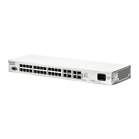
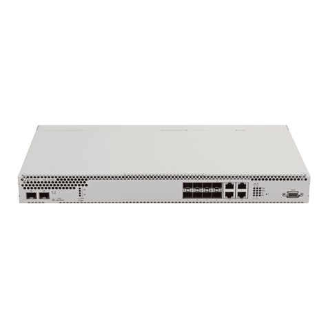
ELTEX MES53xx User manual

MES53xx, MES33xx, MES23xx
Operation Manual, Firmware Version 4.0.4
Backbone Switches, Aggregation Switches, Access Switches

MES53xx, MES33xx, MES23xx Ethernet Switch Series 2
Document Version
Issue Date
Revisions
Version 1.4
09.09.2016
Chapter added:
2.4 Design –MES2308 Switch description is added
5.8 Configuring ‘time-range’ intervals
5.15.8 Configuring OAM protocol
5.17.4 Function of the multicast traffic limitation
5.24 Power supply via Ethernet (PoE) lines
5.27 Configuring PPPoE Intermediate Agent
Changes in sections:
2.3 The main technical specification
5.4 System control commands
5.7 System time configuration
5.8 Configuring interfaces
5.12 IPv4-addressing configuration
5.15.5 STP (STP, RSTP, MSTP)
5.17.1 Rules of multicast addressing
5.17.2 Agent function of IGMP (IGMP Snooping)
5.19.1 AAA mechanism
5.19.2 RADIUS protocol
5.19.4 TACACS+ protocol
5.19.5 SNMP
Version 1.3
22.07.2016
Chapter added:
5.15.6 Configuring G.8032v2 (ERPS)
Changes in sections:
2.2.3 L2 functions of the OSI model
5.4 Command of system control
5.8.2 VLAN interface configuration
5.19.1 AAA mechanism
5.19.8.1 Telnet, SSH, HTTP and FTP
5.20 Error log, SYSLOG protocol
5.27 ACL configuration (Access Control List)
Version 1.2
25.05.2016
Chapter added:
2.3 Main Specifications
2.4 MES2348B Switch Design
Version 1.1
12.05.2016
Chapter added:
2.3 Main Specifications
2.4 MES3324 and MES2324 Switch Design
Chapter deleted:
5.14.2 IPv6 Protocol Tunnelling (ISATAP)
Version 1.0
25.03.2016
First issue
Firmware Version
4.0.4

MES53xx, MES33xx, MES23xx Ethernet Switch Series 3
CONTENTS
1 INTRODUCTION ...........................................................................................................................................7
2 PRODUCT DESCRIPTION ..............................................................................................................................8
2.1 Purpose................................................................................................................................................8
2.2 Switch Features ...................................................................................................................................8
2.2.1 Basic Features ............................................................................................................................8
2.2.2 MAC address processing features .............................................................................................8
2.2.3 Layer 2 Protocol Tunneling (L2PT) Features ..............................................................................9
2.2.4 Layer 3 Protocol Tunneling (L3PT) Features ............................................................................11
2.2.5 QoS Features............................................................................................................................11
2.2.6 Security features......................................................................................................................12
2.2.7 Switch Control Features...........................................................................................................12
2.2.8 Additional Features..................................................................................................................14
2.3 Main specifications............................................................................................................................14
2.4 Design ................................................................................................................................................18
2.4.1 Appearance and description of the front panel of MES53xx, MES33xx, MES23xx switches. .18
2.5 Rear panel of the device....................................................................................................................23
2.5.1 Side panels of the device .........................................................................................................25
2.5.2 Light Indication ........................................................................................................................25
2.6 Delivery Package................................................................................................................................27
3 INSTALLATION AND CONNECTION............................................................................................................28
3.1 Support brackets mounting...............................................................................................................28
3.2 Device rack installation......................................................................................................................28
3.3 Power module installation ................................................................................................................30
3.4 Connection to power supply .............................................................................................................30
3.5 Battery connection to MES2324B, MES2324FB, MES2348B.............................................................31
3.6 SFP transceiver installation and removal ..........................................................................................31
4 INITIAL SWITCH CONFIGURATION.............................................................................................................33
4.1 Configuring the Terminal...................................................................................................................33
4.2 Turning on the device........................................................................................................................33
4.3 Startup menu.....................................................................................................................................34
4.4 Switch operation modes....................................................................................................................34
4.4.1 Switch operation in stacking mode .........................................................................................34
4.5 Switch function configuration ...........................................................................................................36
4.5.1 Basic switch configuration.......................................................................................................36
4.5.2 Security system configuration .................................................................................................39
4.5.3 Banner configuration...............................................................................................................40
5 DEVICE MANAGEMENT. COMMAND LINE INTERFACE .............................................................................41
5.1 Basic commands ................................................................................................................................41
5.2 Filtering command line messages .....................................................................................................43
5.3 Macrocommand configuration..........................................................................................................43
5.4 System management commands ......................................................................................................44
5.5 Password parameters configuration commands ..............................................................................48
5.6 File operations...................................................................................................................................49
5.6.1 Command parameters description..........................................................................................49
5.6.2 File operation commands ........................................................................................................49
5.6.3 Automatic update and configuration commands....................................................................51
5.7 System time configuration ................................................................................................................52
5.8 Configuring time ranges ....................................................................................................................56
5.9 Interface configuration......................................................................................................................56
5.9.1 Ethernet, Port-Channel and Loopback interface parameters .................................................56
5.9.2 VLAN interface configuration ..................................................................................................65

MES53xx, MES33xx, MES23xx Ethernet Switch Series 4
5.10 Selective Q-in-Q ................................................................................................................................ 71
5.11 Broadcast Storm Control .................................................................................................................. 72
5.12 Link Aggregation Groups (LAG)......................................................................................................... 73
5.12.1 Static link aggregation groups.............................................................................................. 74
5.12.2 LACP link aggregation protocol............................................................................................ 75
5.13 IPv4 addressing configuration .......................................................................................................... 76
5.14 Green Ethernet configuration........................................................................................................... 77
5.15 IPv6 addressing configuration .......................................................................................................... 79
5.15.1 IPv6 protocol........................................................................................................................ 79
5.16 Protocol configuration...................................................................................................................... 82
5.16.1 DNS configuration................................................................................................................ 82
5.16.2 ARP configuration ................................................................................................................ 83
5.16.3 GVRP configuration.............................................................................................................. 84
5.16.4 Loopback detection mechanism.......................................................................................... 85
5.16.5 STP family (STP, RSTP, MSTP) .............................................................................................. 86
5.16.6 G.8032v2 (ERPS) protocol configuration ............................................................................. 92
5.16.7 LLDP configuration............................................................................................................... 94
5.16.8 OAM protocol configuration................................................................................................ 99
7.1 Voice VLAN...................................................................................................................................... 102
7.2 Multicast addressing....................................................................................................................... 103
7.2.1 Multicast addressing rules .................................................................................................... 103
7.2.2 IGMP snooping function ....................................................................................................... 108
7.2.3 MLD snooping is a multicast traffic control protocol for IPv6 networks.............................. 111
7.2.4 Multicast-traffic restriction................................................................................................... 113
7.2.5 IGMP Proxy multicast routing function................................................................................. 115
7.3 Multicast routing. PIM protocol ..................................................................................................... 116
7.4 Control functions ............................................................................................................................ 119
7.4.1 AAA mechanism .................................................................................................................... 119
7.4.2 RADIUS .................................................................................................................................. 123
7.4.4 TACACS+................................................................................................................................ 125
7.4.5 Simple network management protocol (SNMP)................................................................... 126
7.4.6 Remote network monitoring protocol (RMON).................................................................... 129
7.4.7 ACL access lists for device management .............................................................................. 136
7.4.8 Access configuration ............................................................................................................. 137
7.5 Alarm log, SYSLOG protocol............................................................................................................ 141
7.6 Port mirroring (monitoring)............................................................................................................ 143
8.1 sFlow function................................................................................................................................. 144
8.2 Physical layer diagnostics functions ............................................................................................... 146
8.2.1 Copper-wire cable diagnostics.............................................................................................. 146
8.2.2 Optical transceiver diagnostics ............................................................................................. 147
8.3 Power supply via Ethernet (PoE) lines............................................................................................ 148
11.1 Security functions ........................................................................................................................... 151
11.1.1 Port security functions....................................................................................................... 151
11.1.2 Port-based client authentication (802.1x standard).......................................................... 153
11.1.3 DHCP management and Option 82.................................................................................... 159
11.1.4 Client IP address protection (IP Source Guard) ................................................................. 162
11.1.5 ARP Inspection ................................................................................................................... 164
11.2 DHCP Relay features ....................................................................................................................... 166
11.1 PPPoE Intermediate Agent (PPPoEIA) configuration...................................................................... 167
11.2 DHCP Server Configuration............................................................................................................. 169
11.3 ACL Configuration ........................................................................................................................... 172
11.3.1 IPv4-based ACL Configuration............................................................................................ 174
11.3.2 IPv6 ACL Configuration ...................................................................................................... 177

MES53xx, MES33xx, MES23xx Ethernet Switch Series 5
11.3.3 MAC-based ACL Configuration ...........................................................................................179
11.4 DoS attack protection configuration ...............................................................................................180
11.5 Quality of Services (QoS) .................................................................................................................181
11.5.1 QoS Configuration ..............................................................................................................181
11.5.2 QoS Statistics ......................................................................................................................187
11.6 Routing protocol configuration .......................................................................................................188
11.6.1 Static Routing Configuration...............................................................................................188
11.6.2 RIP Configuration................................................................................................................189
11.6.3 OSPF and OSPFv3 configuration .........................................................................................191
11.6.4 Configuration of Virtual Router Redundancy Protocol (VRRP)...........................................196
12 SERVICE MENU, CHANGE OF FIRMWARE................................................................................................198
12.1 Startup Menu...................................................................................................................................198
12.2 Updating firmware from TFTP server..............................................................................................198
12.2.1 System firmware update ....................................................................................................198
APPENDIX A. EXAMPLE OF DEVICE USAGE AND CONFIGURATION..............................................................201
APPENDIX B. CONSOLE CABLE......................................................................................................................205
APPENDIX C. SUPPORTED ETHERTYPE VALUES............................................................................................206

MES53xx, MES33xx, MES23xx Ethernet Switch Series 6
LEGEND
Label
Description
[ ]
Square brackets are used to indicate optional parameters in the command
line; when entered, they provide additional options.
{}
Curly brackets are used to indicate mandatory parameters in the command
line. You need to choose one of them.
-
In the command description, these characters are used to define ranges.
In the command description, this character means 'or'.
In the command description, this character indicates the default value.
Calibri Italic
Calibri Italic is used to indicate variables and parameters that should be
replaced with an appropriate word or string.
Bold
Notes and warnings are shown in semibold.
<Bold Italic>
Keyboard keys are shown in bold italic within angle brackets.
Courier New
Command examples are shown in Courier New Bold.
Courier New
Command execution results are shown in Courier New in a frame with a
shadow border.
Notes and Warnings
Notes contain important information, tips or recommendations on device operation and
set-up.
Warnings tell the user about situations that may be harmful to the user, cause damage
to the device, malfunction or data loss.

MES53xx, MES33xx, MES23xx Ethernet Switch Series 7
1INTRODUCTION
Over the last few years, more and more large-scale projects are utilising NGN concept in
communication network development. One of the main tasks in implementing large multiservice networks
is to create reliable high-performance backbone networks for multilayer architecture of next-generation
networks.
High-speed data transmission, especially in large-scale networks, requires a network topology that
will allow flexible distribution of high-speed data flows.
MES53xx, MES33xx, MES23xx series switches can be used in large enterprise networks, SMB
networks and carrier networks. These switches deliver high performance, flexibility, security, and multi-
tier QoS. MES5324 and MES3324 switches provide better availability due to protection of nodes that
enable fail-over operation and backup of power and ventilation modules.
This operation manual describes intended use, specifications, first-time set-up recommendations,
and the syntax of commands used for configuration, monitoring and firmware update of the switches.

MES53xx, MES33xx, MES23xx Ethernet Switch Series 8
2PRODUCT DESCRIPTION
2.1 Purpose
High-performance aggregation switches MES5324 and MES3324 have 10GBASE-X, 40GBASE-X ports
and are designed to be used in carrier networks as aggregation devices and in data processing centres as
top-of-rack or end-of-row switches.
The ports support 40 Gbps (QSFP) (MES5324), 10 Gbps (SFP+) or 1 Gbps (1000BASE-X and
1000BASE-T SFP) for higher flexibility and ensure that you can gradually move to higher transfer rates.
Non-blocking switch fabric ensures correct packet processing with minimal and predictable latency at
maximum load for all types of traffic.
Front-to-back ventilation ensures efficient cooling in data processing centres.
Redundancy fans and AC or DC power supplies along with a comprehensive hardware monitoring
system ensure high reliability. The devices allow hot swapping of power and ventilation modules providing
smooth network operation.
MES2324 and MES2348 series access switches are L2+ managed switches with 24-
48x10/100/1000Base-T ports and 4x10GBase-X (SFP+)/1000Base-X (SFP) ports.
MES2308 access switches include 10x10/100/1000Base-T ports, (MES2308P –8x10/100/1000Base-T
ports supporting PoE+, and 2x10/100/1000Base-T ports), 2x1000Base-X (SFP) ports.
The switches provide end users with connection to SMB networks and carrier networks through the
Gigabit Ethernet interface.
2.2 Switch Features
2.2.1 Basic Features
Table 2.1 lists the basic administrable features of the devices of this series.
Table 2.1. Basic features of the device
Head-of-Line blocking
(HOL)
HOL blocking occurs when device output ports are overloaded with traffic coming
from input ports. It may lead to data transfer delays and packet loss.
Jumbo frames
Enables jumbo frame transmission to minimize the amount of transmitted
packets. This reduces overhead, processing time and interruptions.
Flow control
(IEEE 802.3X)
With flow control you can interconnect low-speed and high-speed devices. To
avoid buffer overrun, the low-speed device can send PAUSE packets that will force
the high-speed device to pause packet transmission.
Operation in device
stack
You can combine multiple switches in a stack. In this case, switches are considered
as a single device with shared settings. There are two stack topologies—ring and
chain. All port parameters of each stack unit can be configured from the master
switch. Device stacking allows for reducing network management efforts.
2.2.2 MAC address processing features
Table 2.2 lists MAC address processing features.

MES53xx, MES33xx, MES23xx Ethernet Switch Series 9
Table 2.2. MAC address processing features
MAC address
table
The switch creates an in-memory look-up table that maps MAC addresses and
switch port nodes.
Learning mode
When learning is not available, the incoming data on a port will be transmitted to
all other ports of the switch. Learning mode allows the switch to analyse the
frame, discover sender's MAC address and add it to the routing table. Then, if the
destination MAC address of an Ethernet frames is already in the routing table, that
frame will be sent only to the port specified in the table.
MAC Multicast support
This feature enables one-to-many and many-to-many data distribution. Thus, the
frame addressed to a multicast group will be transmitted to each port of the
group.
Automatic Aging for
MAC Addresses
If there are no packets from a device with a specific MAC address in a specific
period, the entry for this address expires and will be removed. It keeps the switch
table up to date.
Static MAC Entries
The network switch allows you to define static MAC entries that will be saved in
the routing table.
2.2.3 Layer 2 Protocol Tunneling (L2PT) Features
Table 2.3 lists Layer 2 features and special aspects (OSI Layer 2).
Table 2.3. Layer 2 feature description (OSI Layer 2)
IGMP Snooping
(Internet Group
Management Protocol)
IGMP implementation analyses the contents of IGMP packets and discovers
network devices participating in multicast groups and forwards the traffic to the
corresponding ports.
MLD Snooping
(Multicast Listener
Discovery)
MLD protocol implementation allows the device to minimize multicast IPv6 traffic.
MVR
(Multicast VLAN
Registration)
This feature can redirect multicast traffic from one VLAN to another using IGMP
messages and reduce uplink port load. Used in III-play solutions.
Broadcast Storm Control
Broadcast storm is a multiplication of broadcast messages in each host causing
their exponential growth that can lead to the network meltdown. The switches
can restrict the transfer rate for multicast and broadcast frames received and sent
by the switch.
Port Mirroring
Port mirroring is used to duplicate the traffic on monitored ports by sending
ingress or and/or egress packets to the controlling port. Switch users can define
controlled and controlling ports and select the type of traffic (ingress or egress)
that will be sent to the controlling port.
Protected ports
This feature assigns the uplink port to the switch port. This uplink port will receive
all the traffic and provide isolation from other ports (in a single switch) located in
the same broadcast domain (VLAN).
Private VLAN Edge
This feature isolates the ports in a group (in a single switch) located in the same
broadcast domain from each other, allowing traffic exchange with other ports that
are located in the same broadcast domain but do not belong to this group.

MES53xx, MES33xx, MES23xx Ethernet Switch Series 10
Private VLAN
(light version)
Enables isolation of devices located in the same broadcast domain within the
entire L2 network. Only two port operation modes are implemented—
Promiscuous and Isolated (isolated ports cannot exchange traffic).
Spanning Tree Protocol
Spanning Tree Protocol is a network protocol that ensures loop-free network
topology by converting networks with redundant links to a spanning tree topology.
Switches exchange configuration messages using frames in a specific format and
selectively enable or disable traffic transmission to ports.
IEEE 802.1w Rapid
spanning tree protocol
Rapid STP (RSTP) is the enhanced version of the STP that enables faster
convergence of a network to a spanning tree topology and provides higher
stability.
ERPS (Ethernet Ring
Protection Switching)
protocol
Protocol used for increasing stability and reliability data transmission network
having ring topology. It is realized by reducing recovery network time in case of
breakdown. Recovery time does not exceed 1 second. It is much less than
network changeover time in case of spanningtree protocols usage.
VLAN support
VLAN is a group of switch ports that form a single broadcast domain. The switch
supports various packet classification methods to identify the VLAN they belong
to.
Supporting OAM
protocol
(Operation, Administration,
and Maintenance, IEEE
802.3ah)
Ethernet OAM (Operation, Administration, and Maintenance), IEEE 802.3ah –
functions of data transmission channel level corresponds to channel status
monitor protocol. The protocol uses data blocks of OAM (OAMPDU) to transmit
information about the channel status between connected Ethernet devices. Both
devices must support standard IEEE 802.3ah.
GARP VLAN (GVRP)
GARP VLAN registration protocol dynamically add/removes VLAN groups on the
switch ports. If GVRP is enabled, the switch identifies and then distributes the
VLAN inheritance data to all ports that form the active topology.
Port Based VLAN
Distribution to VLAN groups is performed according to the ingress ports. This
solution ensures that only one VLAN group is used on each port.
802.1Q support
IEEE 802.1Q is an open standard that describes the traffic tagging procedure for
transferring VLAN inheritance information. It allows multiple VLAN groups to be
used on one port.
Link aggregation with
LACP
(Link Aggregation
Control Protocol)
The LACP enables automatic aggregation of separate links between two devices
(switch-switch or switch-server) in a single data communication channel.
The protocol constantly monitors whether link aggregation is possible; in case one
link in the aggregated channel fails, its traffic will be automatically redistributed to
functioning components of the aggregated channel.
LAG group creation
(Link Aggregation
Group)
The device allows for link group creation. Link aggregation, trunking or IEEE
802.3ad is a technology that enables aggregation of multiple physical links into
one logical link. This leads to greater bandwidth and reliability of the backbone
'switch-switch' or 'switch-server' channels. There are three types of balancing—
based on MAC addresses, IP addresses or destination port (socket).
A LAG group contains ports with the same speed operating in full-duplex mode.
Auto Voice VLAN
support
Allows you to identify voice traffic by OUI (Organizationally Unique Identifier—first
24 bits of the MAC address). If the MAC table of the switch contains a MAC
address with VoIP gateway or IP phone OUI, this port will be automatically added
to the voice VLAN (identification by SIP or the destination MAC address is not
supported).

MES53xx, MES33xx, MES23xx Ethernet Switch Series 11
Selective Q-in-Q
Allows you to assign external VLAN SPVLAN (Service Provider’s VLAN) based on
configured filtering rules by internal VLAN numbers (Customer VLAN). Selective Q-
in-Q allows you to break down subscriber’s traffic into several VLANs, change
SPVLAN stamp for the packet in the specific network section.
2.2.4 Layer 3 Protocol Tunneling (L3PT) Features
Table 2.4 lists Layer 3 functions (OSI Layer 3).
Table 2.4. Layer 3 Features description (Layer 3)
BootP and DHCP clients
(Dynamic Host Configuration
Protocol)
The devices can obtain IP address automatically via the BootP/DHCP.
Static IP routes
The switch administrator can add or remove static entries into/from the routing
table.
Address Resolution
Protocol
ARP maps the IP address and the physical address of the device. The mapping is
established on the basis of the network host response analysis; the host address is
requested by a broadcast packet.
Routing Information
Protocol
(RIP)
The dynamic routing protocol that allows routers to get new routing information
from the neighbour routers. This protocol detects optimum routes on the basis of
hops count data.
Supported by MES5324, MES3324F switches
IGMP Proxy function
IGMP Proxy is a feature that allows simplified routing of multicast data between
networks. IGMP is used for routing management.
OSPF protocol (Open
Shortest Path First)
A dynamic routing protocol that is based on a link-state technology and uses
Dijkstra's algorithm to find the shortest route. OSPF protocol distributes
information on available routes between routers in a single autonomous system.
Supported by MES5324, MES3324F switches
Virtual Router
Redundancy Protocol
(VRRP)
VRRP is designed for backup of routers acting as default gateways. This is achieved
by joining IP interfaces of the group of routers into one virtual interface which will
be used as the default gateway for the computers of the network.
Protocl
IndependentMulticast
(PIM)
The Protocol-Independent Multicast protocols for IP networks were created to
address the problem of multicast routing. PIM relies on traditional routing
protocols (such as, Border Gateway Protocol) rather than creates its own network
topology. It uses unicast routing to verify RPF. Routers perform this verification to
ensure loop-free forwarding of multicast traffic.
Supported by MES5324, MES3324F switches
2.2.5 QoS Features
Table 2.5 lists the basic quality of service features.
Table 2.5. Basic quality of service features
Priority queues support
The switch supports egress traffic prioritization with queues for each port. Packets
are distributed into queues by classifying them by various fields in packet headers.
802.1p class of service
support
802.1p standard specifies the method for indicating and using frame priority to
ensure on-time delivery of time-critical traffic. 802.1p standard defines 8 priority

MES53xx, MES33xx, MES23xx Ethernet Switch Series 12
levels. The switches can use the 802.1p priority value to distribute frames
between priority queues.
2.2.6 Security features
Table 2.6. Security features
DHCP snooping
A switch feature designed for protection from DHCP attacks. Enable filtering of
DHCP messages coming from untrusted ports by building and maintaining DHCP
snooping binding database. DHCP snooping performs functions of a firewall
between untrusted ports and DHCP servers.
DHCP Option 82
An option to tell the DHCP server about the DHCP relay and port of the incoming
request.
By default, the switch with DHCP snooping feature enabled identifies and drops all
DHCP requests with Option 82, if they were received via an untrusted port.
UDP relay
Broadcast UDP traffic forwarding to the specified IP address.
DHCP server features
DHCP server performs centralised management of network addresses and
corresponding configuration parameters, and automatically provides them to
subscribers.
IP Source address guard
The switch feature that restricts and filters IP traffic according to the mapping
table from the DHCP snooping binding database and statically configured IP
addresses. This feature is used to prevent IP address spoofing.
Dynamic ARP Inspection
(Protection)
A switch feature designed for protection from ARP attacks. The switch checks the
message received from the untrusted port: if the IP address in the body of the
received ARP packet matches the source IP address.
If these addresses do not match, the switch drops this packet.
L2 –L3 –L4 ACL (Access
Control List)
Using information from the level 2, 3, 4 headers, the administrator can configure
up to 1024 rules for processing or dropping packets.
Time Based ACL
Allow you to configure the time frame for ACL operation.
Blocked ports support
The key feature of blocking is to improve the network security; access to the
switch port will be granted only to those devices whose MAC addresses were
assigned for this port.
Port based
authentication (802.1x
standard)
IEEE 802.1x authentication mechanism manages access to resources through an
external server. Authorized users will gain access to the specified network
resources.
2.2.7 Switch Control Features
Table 2.7. Switch control features
Uploading and
downloading the
configuration file
Device parameters are saved into the configuration file that contains configuration
data for the specific device ports as well as for the whole system.

MES53xx, MES33xx, MES23xx Ethernet Switch Series 13
Trivial File Transfer
Protocol (TFTP)
The TFTP is used for file read and write operations. This protocol is based on UDP
transport protocol.
The devices are able to download and transfer configuration files and firmware
images via this protocol.
Secure Copy protocol
(SCP)
SCP is used for file read and write operations. This protocol is based on SSH
network protocol.
The devices are able to download and transfer configuration files and firmware
images via this protocol.
Remote monitoring
(RMON)
Remote network monitoring (RMON) is an extension of SNMP that enables
monitoring of computer networks. Compatible devices gather diagnostics data
using the network management station. RMON is a standard MIB database that
contains actual and historic MAC-level statistics and control objects that provide
real-time data.
Simple Network
Management Protocol
(SNMP)
SNMP is used for monitoring and management of network devices. To control
system access, the community entry list is defined where each entry contains
access privileges.
Command Line Interface
(CLI)
Switches can be managed using CLI locally via serial port RS-232, or remotely via
telnet or ssh. Console command line interface (CLI) is an industrial standard. CLI
interpreter provides a list of commands and keywords that help the user and
reduce the amount of input data.
Syslog
Syslog is a protocol designed for transmission of system event messages and error
notifications to remote servers.
Simple Network Time
Protocol
(SNTP)
SNTP is a network time synchronization protocol; it is used to synchronize time on
a network device with the server and can achieve accuracy of up to 1ms.
Traceroute
Traceroute is a service feature that allows the user to display data transfer routes
in IP networks.
Privilege level controlled
access management
The administrator can define privilege levels for device users and settings for each
privilege level (read-only - level 1, full access - level 15).
Management interface
blocking
The switch can block access to each management interface (SNMP, CLI). Each type
of access can be blocked independently:
Telnet (CLI over Telnet Session)
Secure Shell (CLI over SSH)
SNMP
Local authentication
Passwords for local authentication can be stored in the switch database.
IP address filtering for
SNMP
Access via SNMP is allowed only for specific IP addresses that are the part of the
SNMP community.
RADIUS client
RADIUS is used for authentication, authorization and accounting. RADIUS server
uses a user database that contains authentication data for each user. The switches
implement a RADIUS client.
Terminal Access
Controller Access
Control System
(TACACS+)
The device supports client authentication with TACACS+ protocol. The TACACS+
protocol provides a centralized security system that handles user authentication
and a centralized management system to ensure compatibility with RADIUS and
other authentication mechanisms.

MES53xx, MES33xx, MES23xx Ethernet Switch Series 14
SSH server
SSH server functionality allows SSH clients to establish secure connection to the
device for management purposes.
Macrocommand
support
This feature allows the user to create sets of commands—macrocommands—and
user them to configure the device.
2.2.8 Additional Features
The table lists additional device features.
Table 2.8. Additional functions
Virtual Cable Test (VCT)
The network switches are equipped with the hardware and software tools that
allow them to perform the functions of a virtual cable tester (VCT). The tester
check the condition of copper communication cables.
Optical transceiver
diagnostics
The device can be used to test the optical transceiver. During testing, the device
monitors the current, power voltage and transceiver temperature. To use this
function, these features should be supported by the transceiver.
Green Ethernet
This mechanism reduces power consumption of the switch by disabling inactive
electric ports.
2.3 Main specifications
Table 2.9 lists main specifications of the switch.
Table 2.9. Main specifications
General parameters
Packet processor
MES5324
Marvell 98CX8129-A1 (Hooper)
MES3324F
Marvell 98DX3336-A1 (PonCat3)
MES2324,
MES2324B,
MES2324FB
MES2348B
MES2308
MES2308P
Marvell 98DX3236-A1 (AlleyCat3)
Interfaces
MES5324
1x10/100/1000Base-T (OOB), 1x10/100/1000Base-T (Management),
24x10G Base-X(SFP+)/1000Base-X (SFP), 4x40G Base-SR4/LR4 (QSFP)
MES3324F
1x10/100/1000Base-T (OOB),
20x1000 Base-X (SFP), 4x(10G Base-X(SFP+)/1000Base-X (SFP),
4x10/100/1000 Base-T/1000 Base-X Combo
MES2324,
MES2324B
24x10/100/1000Base-T, 4x(10G Base-X(SFP+)/1000Base-X (SFP))
MES2324FB
20x1000 Base-X (SFP)
4x(10G Base-X(SFP+)/1000Base-X (SFP)
4x10/100/1000 Base-T/1000 Base-X Combo
MES2348B
48x10/100/1000Base-T, 4x(10G Base-X(SFP+)/1000Base-X (SFP))
MES2308
10x10/100/1000Base-T
2x1000Base-X(SFP)

MES53xx, MES33xx, MES23xx Ethernet Switch Series 15
MES2308P
8x10/100/1000Base-T (PoE+)
2x10/100/1000Base-T
2x1000Base-X (SFP)
Capacity
MES5324
800 Gbps
MES3324F
MES2324,
MES2324B,
MES2324FB
128 Gbps
MES2348B
176 Gbps
MES2308,
MES2308P
24 Gbps
Buffer memory
MES5324
32Mb
MES3324F
MES2324,
MES2324B,
MES2308,
MES2324FB,
MES2348B
12Mb
MES2348B
24 Mb
MAC Address Table
MES5324
64K entries (some MAC addresses are reserved by the system).
MES3324F,
MES2324,
MES2324B,
MES2324FB,
MES2348B,
MES2308,
MES2308P
16K entries (some MAC addresses are reserved by the system).
TCAM routing volume
MES5324
2 K
MES3324F
3 K
MES2324,
MES2324B,
MES2324FB,
MES2348B,
MES2308,
MES2308P
1 K
L3 Unicast routs
number
MES5324
8K
MES3324F
13K
MES2324
MES2324B
MES2348B
MES2324FB
MES2308
MES2308P
L3 functionality is disabled
ARP records number
MES5324
8K
MES3324F
4K

MES53xx, MES33xx, MES23xx Ethernet Switch Series 16
MES2324
MES2324BM
ES2324FB
MES2348B
MES2308
MES2308P
1K
L2 Multicast (IGMP
snooping) group
number
MES5324
4K
MES3324F
4K
MES2348B
MES2324
MES2324BM
ES2324FB
MES2308
MES2308P
2K
L3 Multicast
(IGMPProxy, PIM) rout
number
MES5324
4K
MES3324F
4K
MES2348B
MES2324
MES2324BM
ES2324FB
MES2308
MES2308P
L3 functional is disabled
Data transfer rate
MES5324
optical interfaces 1/10/40 Gbpselectric interfaces 10/100/1000Mbps
SQinQ rules number
MES5324
1375(ingress)/75(egress)
MES3324F
1320(ingress)/72(egress)
MES2324
MES2348B
MES2324BM
ES2324F
MES2308
MES2308P
360(ingress)/72(egress)
VLAN support
up to 4K active VLANs as per 802.1Q
Quality of Services (QoS)
Traffic priority, 8 tiers
8 output queues with different priorities for each port
Total number of VRRP routers
255
Total number of L3 interfaces
up to 129
Total number of virtual Loopback
interfaces
64
LAG
16 groups with up to 8 ports in each
MSTP instances qty
64
Jumbo frames
Max. packet size 10K
Stacking
Up to 8 devices

MES53xx, MES33xx, MES23xx Ethernet Switch Series 17
Compliance
IEEE 802.3 10BASE-T Ethernet
IEEE 802.3u 100BASE-T Fast Ethernet
IEEE 802.3ab 1000BASE-T Gigabit Ethernet
IEEE 802.3z Fiber Gigabit Ethernet
IEEE 802.3x Full Duplex, Flow Control
IEEE 802.3ad Link Aggregation (LACP)
IEEE 802.1p Traffic Class
IEEE 802.1q VLAN
IEEE 802.1v
IEEE 802.3 ac
IEEE 802.1d Spanning Tree Protocol (STP)
IEEE 802.1w Rapid Spanning Tree Protocol (RSTP)
IEEE 802.1s Multiple Spanning Tree Protocol (MSTP)
IEEE 802.1x Authentication
IEEE 802.3af PoE, IEEE 802.3at PoE+ (only for MES2308P)
Control
Local control
Console
Remote control
SNMP, Telnet, SSH, WEB
Physical specifications and ambient conditions
Power supply
MES5324
MES3324F
AC: 220V+-20%, 50 Hz
DC: -36.. -72V
Power options:
- Single AC or DC power supply
- Two AC or DC hot-swappable power supplies
MES2324
MES2308
MES2308P
AC: 220V+-20%, 50 Hz
MES2324B,
MES2324FB,
MES2348B
AC: 220V+-20%, 50 Hz
and a lead-acid battery.
Charger specifications:
- charge current - 1.7 A;
- voltage of the load current release - 10–10.5 V;
- threshold voltage for low batter indication - 11 V
Battery connection wire size -
Battery capacity - min 20Ah (for example, GP12200)
Power consumption
MES5324
MES3324F
max 85 W
MES2324
max 25 W
MES2324B
max 50 W
MES2324FB
max 45 W
MES2348B
max 44 W / max 84 W (including for battery charging)
MES2308
up to 12,5 W
MES2308P
up to 275 W
Dimensions
MES5324
MES3324F
430x298x44 mm
430 x 280 x 44 mm
MES2324
MES2324B
430 x 158 x 44 mm
MES2324FB
430 x 243 x 44 mm
MES2348B
430 x 280 x 44 mm

MES53xx, MES33xx, MES23xx Ethernet Switch Series 18
MES2308
310 x 158 x 44 mm
MES2308P
430 х 158 х 44 mm
Operating temperature range
from -20 to +45°C
Storage temperature range
from -40 to +70°C
Operational relative humidity (non-
condensing)
up to 40%
Storage relative humidity (non-
condensing)
from 10% to 95%
Average lifetime
20 years
Power supply type is specified when ordering.
2.4 Design
This section describes the design of devices. It provides the images of front, rear and side panels of
the device, the description of connectors, LED indicators and controls.
Ethernet switches MES53xx, MES33xx, MES23xx have a metal-enclosed design for 1U 19" racks.
2.4.1 Appearance and description of the front panel of MES53xx, MES33xx, MES23xx
switches.
Front panel layout of the MES53xx, MES33xx and MES23xx series is shown in Figure 1–8.
Figure 1. MES5324, front panel
.
Table 2.10 lists connectors, LEDs and controls located on the front panel of the switch.
Table 2.10. Description of MES5324 connectors, LEDs and front panel controls
No
Front panel element
Description
1
Unit ID
Indicator of the stack unit number.
Power
Device power LED.
Master
Device operation mode LED (master/slave).
Fan
Fan operation LED.
RPS
Backup power supply LED.

MES53xx, MES33xx, MES23xx Ethernet Switch Series 19
2
Console
Console port for local management of the device.
Connector pinning:
1not used
2not used
3RX
4GND
5GND
6TX
7not used
8not used
9not used
Soldering pattern of the console pattern is given in Appendix B
3
USB
USB port.
4
OOB
Out-of-band 10/100/1000 Base-T (RJ-45) port for remote device
management.
Management is performed over network other than the transportation
network.
5
Mgmt
10/100/1000 Base-T (RJ-45) port for remote device management over the
transportation network.
6
F
Functional key that reboots the device and resets it to factory default
configuration:
- pressing the key for less than 10 seconds reboots the device.
- pressing the key for more than 10 seconds resets the device to factory
default configuration.
7
[1-24]
Slots for 10G SFP+/ 1G SFP transceivers.
8
XLG1, XLG2
XLG3, XLG4
Slots for XLG1-XLG4 transceivers.
Transceivers 40GQSFP.
Figure 2. MES3324F, front panel
Table 2.11 lists connectors, LEDs and controls located on the front panel of the MES3324F switch.
Table 2.11. Description of MES3324F connectors, LEDs and front panel controls
No
Front panel element
Description
1
UnitID
Indicator of the stack unit number.
Power
Device power LED.
Master
Device operation mode LED (master/slave).
Fan
Fan operation LED.
RPS
Backup power supply LED.
2
Console
Console port for local management of the device.

MES53xx, MES33xx, MES23xx Ethernet Switch Series 20
3
OOB
Out-of-band 10/100/1000 Base-T (RJ-45) port for remote device
management.
Management is performed over network other than the transportation
network.
4
F
Functional key that reboots the device and resets it to factory default
configuration:
- pressing the key for less than 10 seconds reboots the device.
- pressing the key for more than 10 seconds resets the device to factory
default configuration.
5
[1-24]
Slots for 1GSFP transceivers.
6
[11-12, 23-24]
Combo ports: 10/100/1000 Base-T (RJ45) ports
7
XG1, XG2
XG3, XG4
Slots for 10GSFP+/ 1GSFP transceivers.
Figure 3. MES2324, front panel
Figure 4. MES2324B, front panel
Figure 5. MES2324FB, front panel
Figure 6. MES2348B, front panel
This manual suits for next models
2
Table of contents
Other ELTEX Switch manuals