MRMC Robotic Pod User manual

Robotic Pod
(Stadium)
Quick Start Guide
Part number: MRMC-1464-00
Product code: MRMC-1292-C

ii
Robotic Pod (Stadium) Quick Start Guide
Part number: MRMC-1464-00
Product code: MRMC-1292-C
© 2017 Mark Roberts Motion Control Ltd. All rights reserved.
No part of this publication may be reproduced, transmitted, or translated
by any means — graphical, electronic, or mechanical — including
photocopying, recording, taping, or storage in an information retrieval
system, without the express written permission of Mark Roberts Motion
Control.
Although every care has been taken to ensure that the information in this
document is accurate and up to date, Mark Roberts Motion Control
continuously strives to improve their products and may make changes to
the hardware, firmware, and software described in this document. Mark
Roberts Motion Control therefore cannot be held responsible for any
error or omission in this document.
All product names mentioned herein are the trademarks or registered
trademarks of their respective owners.
Contact information
Mark Roberts Motion Control Ltd.
Unit 3, South East Studios
Blindley Heath
Surrey
RH7 6JP
United Kingdom
Telephone: +44 (0) 1342 838000
E-mail: info@mrmoco.com (sales and general enquiries)
Web: www.mrmoco.com
www.mrmocorentals.com

iii
Robotic Pod (Stadium) Quick Start GuideRobotic PodQuick Start Guide
Contents
Chapter 1 Quick Start..................................................................... 1
Important safety instructions ...............................................1
Power and connections ................................................1
General care...................................................................1
Location .........................................................................2
Intellectual property.....................................................2
Overview .................................................................................3
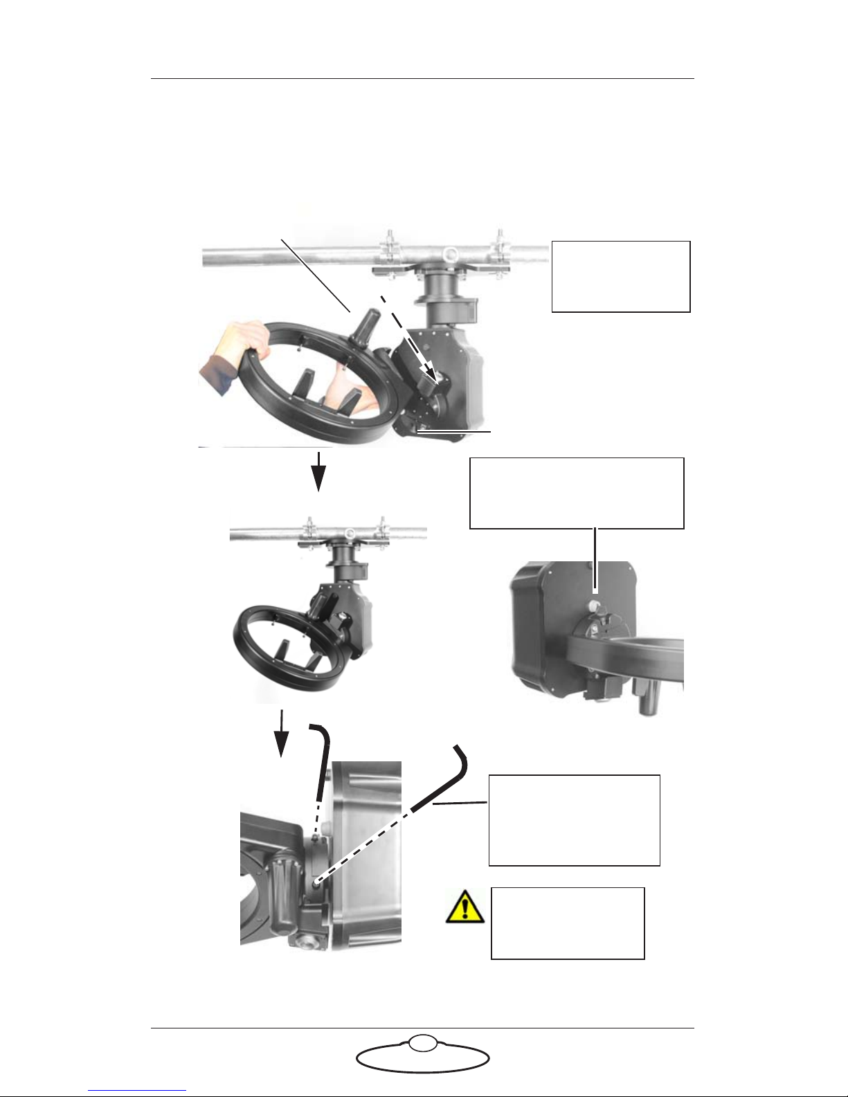
Setting up the hardware ........................................................3
Connecting the cables ...........................................................9
Setting up the Robotic Pod System using the MHC
software .................................................................................11
Home Zeroing .....................................................................12
Changing system configuration and network settings....13
Launching MHC as Admin .......................................13
Network setup ......................................................................15
Adding Pods ................................................................15
Adding Pods by using FIND............................15
Adding Pods manually......................................16
Changing a Pod’s name..............................................16
Assigning Pods to user(s) ..........................................16
Removing a Pod..........................................................17
Editing network settings on the Pod........................17
Adding users.........................................................................17
Changing the Server IP address................................18
Logging in as a User ...................................................18
TDCGraphics software ..............................................19
Port tabs .......................................................................20
Polycam system ....................................................................22
Polycam settings..........................................................22
Tracking data...............................................................26

Robotic Pod Quick Start Guide
iv
Lens tab .................................................................................27
Linearise Zoom button .....................................28
Importing lens settings .....................................28
Exporting lens settings .....................................28
Infinity offset......................................................29
Lens Focal Length .............................................29
Sensor Width and Height.................................30
Use Pan to Calibrate FOV ................................30
Focus calibration ...............................................30
Zoom linearisation............................................31
Tools tab.......................................................................32
EXPORT ROBOT SETTINGS.........................32
Reset Robot ........................................................33
IMPORT ROBOT SETTINGS.........................34
Reset Camera ....................................................34
Camera Direct Connection Toggle ................34
TenPin Init .........................................................34
Subsequent sessions.............................................................34
Appendix 1 Troubleshooting........................................................... 36
Typical symptoms, causes, and actions .............................36
Appendix 2 Pod connectors ............................................................ 39
Connector pin-outs..............................................................39
Panel mount connector..............................................39
Panel mount connector..............................................40
Power In connector ....................................................40
Mains In connector ....................................................41
SDI Out Connector ....................................................41
Appendix 3 Specifications............................................................... 43

1
Robotic Pod (Stadium) Quick Start GuideRobotic Pod (Stadium) Quick Start Guide
Chapter 1 Quick Start
Important safety instructions
To ensure the best from the product, please read this manual carefully.
Keep it in a safe place for future reference.
To reduce the risk of electric shock, do not remove the cover from the
unit. No user serviceable parts inside. Refer servicing to qualified
personnel.
Power and connections
This unit must be connected to a mains socket outlet with a
protective earth connection.
This unit is not disconnected from the AC power source as
long as it is connected to the wall outlet.
When not using the unit for a long period of time, ensure that
the AC power cord is disconnected from the wall outlet.
The AC wall outlet should be installed near to the unit and be
easily accessible.
Do not plug in or attempt to operate an obviously damaged
unit.
General care
Do not force switches or external connections.
When moving the unit, disconnect the mains cable and then
disconnect the long umbilical cable.
Do not attempt to clean the unit with chemical solvents or
aerosol cleaners, as this may damage the unit. Use a clean dry
cloth.
Do not use around flammable gas. All electrical equipment can
generate sparks that can ignite flammable gas.
Keep away from pets and children. The head has powerful
motors that can pinch, so take care not to get your hands
trapped in the head or cabling.

Robotic Pod (Stadium) Quick Start Guide
2
Keep cables tidy. Use cable ties to keep them out of harm’s way.
If you have a head with slip rings then make use of them; avoid
running any cables between the base and the rotating head or
camera.
Location
Installation of this unit should be away from sources of excessive heat,
vibration, and dust.
Intellectual property
This product includes confidential and/or trade secret property.
Therefore, you may not copy, modify, adapt, translate, distribute, reverse
engineer, or decompile contents thereof.

Robotic Pod (Stadium) Quick Start Guide
3
Overview
Thank you for using the robotic Pod camera head from Mark Roberts
Motion Control (MRMC). The Pod head is designed for reliable day-in,
day-out use in professional studio and Outside Broadcast environments.
The versatility of the Pod head makes it suitable for live action, stills, and
time-lapse applications.
You can use the Ethernet connection on the Pod head to connect directly
to a PC running Multi-Head Controller (MHC) software
Setting up the hardware
1. Mount the Pan Tilt Arm (PTA) onto a heavy-duty scaffolding pole
by securing the PTA to the pole using the two scaffolding clamps.
Ensure the nuts on the clamps are tight and the arm cannot twist on
the scaffolding plate.
Note
Ensure the mounting bar can take the weight without stress and that
the space on the bar is free to allow full movement of the pod when
panning without hitting any obstacles. The maximum weight of the
PTA system is 30kg but due to motion and, if mounted outdoors
possible high winds, the bar should be able to support at least 100kg.
The torque setting of the screws in the scaffolding clamps is
159.1Nm. Always ensure there is enough thread going through the
nyloc.

Nuts
PTA underslung
PTA overslung
If the head is going to be
used for target tracking,
then ensure that the PTA
is perfectly levelled to the
ground using a spirit level.
Robotic Pod (Stadium) Quick Start Guide
4

Robotic Pod (Stadium) Quick Start Guide
5
2. Attach the safety cable around the bar, through at least one eyelet,
and through the pan safety hole (near the connector socket).
Remove any excess slack by making extra loops around the bar.
Then join with a carabiner and screw the carabiner shut.
Pan safety hole
Eyelet Wind any excess
cable around
scaffolding pole
Carabiner screwed shu
t
Note
Safety cables should be wound up to keep them short:
In the event of a fall, the falling item has less opportunity
to get speed before the cable catches it.
This prevents them catching on any moving parts.

Robotic Pod (Stadium) Quick Start Guide
6
3. Attach the roll ring to the arm by sliding the roll wedge into the side
plate and ensure the safety catch locks into place —preventing the
roll ring to be detached again. Then tighten the two captive screws
to firmly secure the roll.
Safety catch
Once the roll ring is
attached to the arm, safety
catch locks into place
Roll motor
Do not use the
roll motor as a
carrying handle.
Tighten the screws
using 4mm allen key.
The torque setting of
the screws is 11.2Nm.
Do not touch the
contacts on the roll
ring or the PTA.

Robotic Pod (Stadium) Quick Start Guide
7
4. Attach the pod to the roll ring by sliding the pod front into the roll
ring from rear. Note the pod has a wedge on its bottom that will
slide into a plate on the roll ring. You can use the roll ring to help
support the weight of the pod while mounting by pointing the pod
downwards.
5. Tighten the three screws on roll ring to secure the Pod into the head.
The Pod is not secure
until it is screwed in.
The torque setting of
the screws is 11.2Nm.

Robotic Pod (Stadium) Quick Start Guide
8
6. Attach the safety cable between the pod handle and the roll safety
hole. Ensure you do not tie it around the roll ring. Wind up any
excess cable by looping further through the holes. Screw closed the
carabiner.
Pod handle
Roll safety
handle
Ensure that you do
not tie the safety
cable around the roll
ring.

Robotic Pod (Stadium) Quick Start Guide
9
Connecting the cables
Attach the power cables ensuring each connector is fully secured into the
socket and that the cable or connector is not caught in any moving part.
Communications / POWER 24V
PC running MHC
Software
ETHERNET
SDI OUT
From Mains
100-240V 447-63Hz
1.6A Max
1
2
3
4
USB joystick, such as an XBox
joystick or MRMC Joystick
Controller
5
6
USB
Break-out box

Robotic Pod (Stadium) Quick Start Guide
10
1. Connect the short umbilical cable to the power connectors in the
PTA and the Pod. Ensure the red markers on the socket and the plug
align.
2. Connect one end of the long umbilical cable to the
PTA-1 and the other to the power supply socket in the
break-out box. Ensure the red markers on the socket
and the plug align.
3. Connect one end of the network cable to the Ethernet connector in
the junction box and the other to the PC. If your setup contains
multiple heads connected via Ethernet, then the network cable
would connect to a network switch, which in turn would be
connected to the PC.
4. Connect the SDI Out connector to a video output device using a
standard coaxial cable.
5. Optionally, connect the USB port on the PC to a joystick, such as an
Xbox joystick or a MRMC Joystick Controller. This device gives you
a precise and real-time control of the camera direction and
functions. You can use the MHC screen to control the camera
instead if you omit a joystick.
6. Finally, connect the mains cable to the power supply.

Robotic Pod (Stadium) Quick Start Guide
11
Setting up the Robotic Pod System using the MHC
software
To control and use the Pods, you need to connect them to the network
that has the PC running the MHC server software. You can choose to
assign the Pods to specific users using MHC server. Then, each user can
use the MHC client application to control the Pod assigned to them
1. Attach the cables to the Pod and PC, as described in the previous
section.
2. There is no power switch on the Pod; it is
powered on whenever the mains supply is
attached and live. After you have attached the
power cable, make sure the power indicator
LED on the Pod lights up.
3. Similarly, to turn off the Pod you simply
remove the power cable.
4. Power up the PC. Both the MHC Server and Client applications are
started. The MHC Main page appears.
Observe that the cabled Pod appears as a white or green icon to
show that it is connected over the network.

Robotic Pod (Stadium) Quick Start Guide
12
5. Clicking/tapping the Pod icon enables the Pod and changes the icon
to green showing it is selected for control from the Main page.
Observe that the un-cabled Pods appear as red icons.
Cable together and power up the remaining Pods. They will appear on
MHC connected, as white icons.
Home Zeroing
Pan, Tilt and Roll axes in Pods are absolute encoders making Homing an
automatic function. Therefore these axes do not need to be Homed by the
User. However, the lens axes Zoom and Focus do need to be Homed. To
home the axes, left-click and hold the Pod head icon and select HOME
FOCUS or HOME ZOOM.

Note
The focus and zoom axes must be homed individually. If an error
occurs after homing, do the following:
1. In the > Robot > Axes tab, check that the Status of the axis
is ON in the grey box. If it is not, click the ENABLE button to
turn it on.
Status should
be ON
2. Click/tap the HOME button to home the selected axis.
Robotic Pod (Stadium) Quick Start Guide
13
Changing system configuration and network
settings
Launching MHC as Admin
To change any network setting, you need to be logged in to the MHC
Client as the Administrator.
1. Log out of the User login.
2. Log in to the MHC client as Administrator using the following
credentials:
Username: Admin
Password: Admin1234

Note
At any time, if you need to restart MHC, perform the following steps:
1. Close the MHC Client and the MHC Server windows.
2. Double-click or tap the MHC Server desktop icon to launch it.
3. Double-click or tap the MHC Client icon to launch it. The
MHC Client can be launched on the same or a different
computer present on the same network.
Robotic Pod (Stadium) Quick Start Guide
14

Robotic Pod (Stadium) Quick Start Guide
15
Network setup
Heads on the network Heads not on the network
Manual Pod
addition
Automatic Pod
addition
Settings Log out
Note
You can click the Settings ( ) button to display the Settings menu.
The tabs in the menu are:
Network – Settings regarding connected/connecting Pods
User – Add/change user accounts
The Settings menu is different for Administrator and User login. For
more information on Settings menu for the User login, go to Settings
menu on page 12.
When you log in as the Administrator, the NETWORK SETUP page
launches and provides a general overview of all the Pods linked to the
system’s network. The two row colours represent the status of the Pods:
Green: The Pod is connected and ready to operate.
Grey: The Pod with the IP address is not connected with the
system’s network or is not powered up.
Adding Pods
MHC allows you to add Pods in two ways:
Adding Pods by using FIND
You can click the FIND button to automatically find the
connected Pod(s). This will appear in a new row. Select the

Robotic Pod (Stadium) Quick Start Guide
16
Pod’s row that you want to connect to and click the appearing ADD
button. This will connect the Pod to the system, and move it to the group
of the connected Pods (the green section).
Adding Pods manually
Alternatively, if your Pod is not present at the time and will be connected
later, you can add the Pod by manually typing its IP address. If you know
the IP address of the Pod you want to add, you can use the NEW button,
then enter the IP address, and click ADD NEW.
Then, enter the TYPE of head and a NAME for it.The row for the Pod
stays grey until the Pod is actually present on the network.
Caution
Do not connect a Pod with the same IP address as another Pod on
the network. This would cause an IP address conflict and both Pods
will not function.
Changing a Pod’s name
You can change the name of a connected or disconnected Pod. The name
appears in the ROBOT NAME column. To change the Pod’s name:
1. Select the row for the Pod.
2. Click or tap in the box representing the name of the Pod.
3. Enter the name for the Pod.
Assigning Pods to user(s)
A Pod can only be used by a user, if it is assigned to the user. Assign a Pod
to the user by selecting the user from the drop-down list.
Other manuals for Robotic Pod
1
This manual suits for next models
2
Table of contents
Other MRMC Camera Accessories manuals

MRMC
MRMC MRMC-1488-00 User manual

MRMC
MRMC MRMC-1167-02 User manual

MRMC
MRMC MRMC-1166-02 User manual

MRMC
MRMC MRMC-1502-04 User manual

MRMC
MRMC MRMC-2318-00 User manual

MRMC
MRMC SFH-50 User manual

MRMC
MRMC Robotic Pod User manual

MRMC
MRMC MRMC-2016-00 User manual

MRMC
MRMC MRMC-1096-00 User manual

MRMC
MRMC Pan Bars User manual