ELV Electronik ETH comfort100 User manual

A
B
C
D
E
F
G
H
I
Radio electronic thermostat
ETH comfort100
Operation and display General function
This electronic thermostat for radiators can be used to control
room temperature on the basis of time. The actuator moves a
valve, thereby allowing the amount of heat flowing to the heating
appliance to be controlled. The controller is compatible with all
standard heating appliance valves. The large illuminated display
ensures user-friendly operation. A wireless receiver allows the
device to receive commands from taught-in system components.
Installation can be achieved in 3 easy steps.
Step 1: Inserting (replacing) the batteries
Remove the battery compartment cover.•
Insert 2 new LR6 batteries (Mignon/AA)•
into the side battery compartments, en-
suring they are the right way round.
Reattach the battery compartment cover•
and click into place.
New alkaline batteries have a life of ap-
proximately two years. A battery symbol
() will indicate when the batteries
need to be replaced. After removing the
old batteries, please wait approximately 1 minute before
inserting the new ones. This device does not support op-
eration with rechargeable batteries.
Never recharge standard batteries.
Doing so will present a risk of explosion.
Do not throw the batteries into a fire.
Do not short-circuit batteries.
Used batteries should not be disposed of with
regular domestic waste. Instead, they
should be taken to your local battery dis-
posal point.
Step 2: Setting the date and time of day
The firmware version number will be displayed briefly once
you have inserted/replaced the batteries and then you will be
automatically prompted to set the date and time of day.
Use the setting wheel (C) to set the year (B).•
Confirm with OK (D).•
Use the setting wheel (C) to set the month (B).•
Confirm with OK (D).•
Use the setting wheel (C) to set the day (B).•
Confirm with OK (D).•
Use the setting wheel (C) to set the hour (A).•
Confirm with OK (D).•
Use the setting wheel (C) to set the minute (A).•
Confirm with OK (D).•
The motor will start moving back the control pin while the
entries are still being made.
If “InS” is displayed with a rotating “•
∏
” symbol, this
indicates that the motor is still moving back. Once the
device is ready for the actuator to be installed on the
valve, just “InS” will appear on the display.
The weekly program and other settings can be cus-•
tomisedprior toinstallation.To do this, press the menu
button when “InS” is shown on the display. For further
details, please see “4. Configuration menu”.
Once programming is complete, “InS” will reappear on•
the display and installation (Step 3) can commence.
When “InS” is visible on the display, you can activate
the teach-in function prior to installation by pressing
the
button briefly.
Step 3: Installing the electronic thermostat
The actuator can be installed on all standard heating
valves. There is no need to drain away water or fiddle
around with the heating system before doing this. First,
you need to remove the old thermostat dial:
Turn the thermostat dial anti-•
clockwise as far as it will go (A).
Release the thermal ring of the•
thermostat (B).
Remove the thermostat from•
the valve (C).
An adapter will need to be used in the
case of certain valves. Adapters for Dan-
foss valves (RA, RAV, RAVL) are included in the scope of delivery. For
details, please refer to the adapter overview (see 20).
The adapter must be placed on the valve and turned until•
it is securely seated.
In the case of the RAV adapter, the•
extension supplied must be at-
tached to the valve tappet.
The RA and RAV adapters must, in•
addition, be secured by means of
the bolt and nut supplied.
The electronic thermostat can only
be installed if “InS” is showing on the
display. Following installation, the actuator will perform an
adjustment run so that it can adapt to the valve. During
this process, “AdA” will be displayed.
Place the actuator on the valve.•
Tighten the union nut.•
“InS” will appear on the display, press the OK button.•
The actuator will perform an adjustment run (“AdA” will•
appear on the display, operation not possible).
After that, the actuator will be ready for operation (Auto mode).•
If the adjustment run was initiated prior to installa-
tion, or if an error message will be displayed (F1, F2,
F3); press OK to move the motor back to the “InS”
position.
1. Setting the weekly program
The weekly program allows you to set up to 3 separate
heating periods (7 switching times) for each day of the
week. Programming is performed in relation to the se-
lected days, for which temperatures must be stored for a
period from 00:00 to 23:59.
Press and hold down the menu button for more than•
3 seconds.
“Pro” will appear on the display.•
Confirm with OK.•
“dAy” will appear on the display.•
The setting wheel can be used
to select an individual day of the
week , a l l wo r k i ng da y s, th e w e ek-
end or the entire week (example
shows working days selected).
Confirm with OK.•
Use the setting wheel to set the first time segment (exam-•
ple shows 0:00 to 6:00).
Confirm with OK.•
Then, select the required temperature for the selected time•
segment (example shows 17.0°C).
Confirm with OK.•
Keep repeating this process until you have finished storing•
temperatures for the period from 0:00 to 23:59.
In Auto mode, the temperature can be modified at any time
via the setting wheel. The modified temperature will then
be retained until the next program changeover.
2. Weekly program: Examples
Th e ele ctr oni c the rmo stat a llow s you to s to re up to 3 he at-
ing periods (7 switching times) with individual tempera-
ture settings for each day of the week. The factory set-
ting consists of two heating phases (from 6:00 until 9:00
and from 17:00 until 23:00 respectively) for every single
day of the week:
From 00:00 to 06:00 17.0°C
From 06:00 to 09:00 21.0°C
From 09:00 to 17:00 17.0°C
From 17:00 to 23:00 21.0°C
From 23:00 to 23:59 17.0°C
To represent the switching periods, the display shows
bars for every other switching interval. In this exam-
ple, no bars are shown for the interval from 0:00 to
6:00. Bars are only shown on the display for the in-
tervals from 6:00 to 9:00 and from 17:00 to 23:00.
If a room also needs to be heated at around noon, the cor-
responding program might look like this:
Monday to Sunday
From 00:00 to 06:00 16.0°C
From 06:00 to 09:00 22.0°C
From 09:00 to 12:00 17.0°C
From 12:00 to 14:00 20.0°C
From 14:00 to 17:30 17.0°C
From 17:30 to 23:30 21.0°C
From 23:30 to 23:59 16.0°C
If you have a home office and only want it to be heated
during the day on working days, you can program the fol-
lowing times:
Monday to Friday
From 00:00 to 08:30 17.0°C
From 08:30 to 17:00 21.0°C
From 17:00 to 23:59 17.0°C
Saturday and Sunday
From 00:00 to 23:59 15.0°C
3. Operating modes
To switch between the 3 operating modes described be-
low, press the menu button briefly (these operating modes
can only be selected following installation/Step 3):
Holiday function• ( ) : Set a temperature that is to be
maintained until a fixed point in time.
Manu:• Manual operation – The temperature is set manu-
ally using the setting wheel.
Auto:• W e e k l y p r o g r a m – T h e t e m p e r a t u r e i s c o n t r o l l e d a u t o -
matically in accordance with the stored weekly program.
4. Configuration menu
The configuration menu can be used to modify settings.
To access this menu, press and hold down the menu
button (for more than 3 seconds).
Pro: For setting the weekly program (see Section “1 Set-•
ting the weekly program”)
dAt: For modifying the time of day and date•
POS: For querying the actuator’s current position•
dSt: Automatic switchover at the start or end of daylight•
saving time can be deactivated.
AEr: For setting the “window open” temperature and•
time so that the temperature is automatically reduced
in the event of ventilation
tOF: For setting the offset temperature•
rES: For restoring the factory settings•
Please read this manual carefully in order to help you put
the device into operation. Keep the manual handy so you
can refer to it at a later date!
A Day of the week
B Holiday function ( ), manual operation (Manu), au-
tomatic operation (Auto), “battery empty” symbol
( ), set-back/comfort temperature ( ), “window
open” symbol ( )
C Menu button: Press and hold down the button for more
than 3 seconds to open the configuration menu
D Settingwheel:Formakingadjustments(e.g.temperature)
E Time and date indicator, menu items, functions
F Current temperature setting
G Switching periods set within weekly program
H OK button: For confirming/saving, teaching in
I button: For switc hin g bet wee n set-b ack a nd co m-
fort temperatures
5
2
6
3
7
4
8
A
C
B
D
ELV Elektronik AG · P.O.Box 1000 · D-26787 Leer
UnL: For teaching out all taught-in wireless compo-•
nents
Use the setting wheel to select menu items and the OK but-
ton to confirm your choice. Press the menu button again to
return to the previous level. After 65 seconds without any-
thing happening, the menu will close automatically.
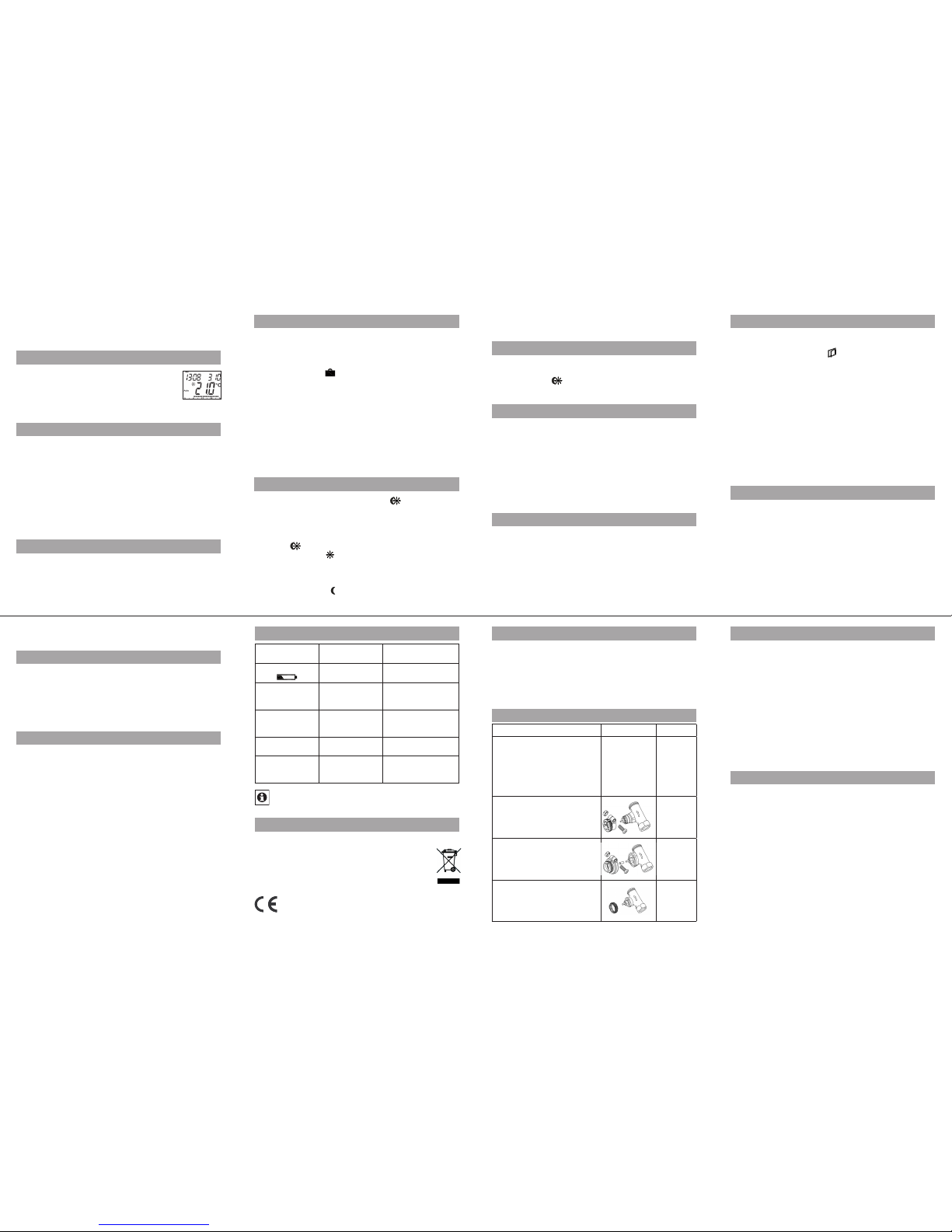
5. Display content during normal operation
During normal operation, the following are dis-
played: day of the week, time of day, date, oper-
ating mode, temperature setting and switching
pe rio ds. T he ba rs indica ting the we ekly program’s
switching p erio ds are s hown fo r every ot her t ime interva l. For an
example, please refer to “2. Weekly program: Examples”
.
6. Teaching in wireless components
The actuator supports the teaching in of up to 4 system
components (e.g. remote control and window contact).
Press and hold down the OK button for more than 3 seconds.•
The remaining teach-in time will be displayed (30 seconds).•
The device being taught-in now needs to send a wireless•
signal (e.g. press button on remote control).
The display will then switch to the normal view.•
On ce this has bee n don e, the ac tua to r will respon d to w ire -
le ss co mma nds f rom t aug ht-i n devic es. W heneve r the ac-
tuator receives a signal from a window contact or remote
control, the display will light up briefly.
7. Teaching out wireless components
Components that have been taught in on the actuator can be
taught out again using the “U nL” (Unle arn) fun cti on. A ll wire-
less components are taught out at once with this function.
Press and hold down the menu button for more than 3 seconds.•
Use the setting wheel to select the “UnL” menu item.•
Confirm with OK.•
“ACC” will appear on the display; press OK to confirm.•
8. Setting the holiday function
If you want a fixed temperature to be maintained for a set
period of time while you are on holiday or during a party,
you can make use of the Holiday function.
Press and release the menu button repeatedly until the•
suitcase symbol ( ) appears on the display.
Use the setting wheel to set the end of the time period•
during which the temperature is to be maintained.
Press the OK button to confirm.•
Then use the setting wheel to set the date.•
Press the OK button to confirm.•
Use the setting wheel to set the temperature; press OK to•
confirm. The display will flash to confirm your settings.
The set temperature will remain in force until the speci-
fied time. After that, the actuator will adopt Auto mode.
Wireless commands from the window contact and remote
control will continue to be executed.
9. Comfort and set-back temperatures
The comfort/set-back temperature button ( ) provides an easy
and convenient way of switching between these two temperatures.
The factory settings are 21.0°C and 17.0°C respectively. To adapt
them, proceed as follows:
Press and hold down the comfort/set-back temperature•
button ( ) for more than 3 seconds.
The sun symbol (• ) will appear on the display along
with the current comfort temperature.
Use the setting wheel to modify the temperature; press•
OK to confirm.
The moon symbol (• ) will appear together with the set-
back temperature.
Use the setting wheel to modify the temperature; press•
OK to confirm.
The temperature can even be modified in Auto mode at any
time by using this button. The new setting will be retained
until the program’s next switching time.
10. Child-proof lock/Operating inhibit
Operation can be inhibited.
To activate/deactivate the operating inhibit, briefly press•
the Menu and buttons at the same time.
Once the function is active, “LOC” will appear on the display.•
To deactivate the function, press both buttons again.•
11. Setting the heating break
If the heating is being switched off for the summer, you
can save battery power. This involves opening the valve
up fully. Limescale protection measures remain in place.
Wireless commands from the window contact or remote
control will no longer be executed.
To activate the heating break, turn the setting wheel•
clockwise during manual operation (Manu) until “On”
appears on the display.
To terminate the heating break, quit manual operation•
(Manu) or turn the setting wheel anticlockwise.
12. Setting frost protection mode
If you do not want the room to be heated, the valve can
be closed. It will only be opened again if there is a risk of
freezing due to frost. Limescale protection measures re-
main in place. Wireless commands from the window con-
tact or remote control will no longer be executed.
To activate frost protection mode, turn the setting wheel•
anticlockwise during manual operation (Manu) until
“OFF” appears on the display.
To terminate frost protection mode, quit manual opera-•
tion (Manu) or turn the setting wheel clockwise.
13. “Window open” function
If the room is being ventilated, the actuator controls the tem-
perature to save on heating costs. While this function is active,
the “window open” symbol ( ) appears on the display.
Wi th out win dow con ta ct : The actuator will automatically de-
tect a significant drop in temperature due to ventilation. You
can set your own “window open” temperature and time.
With taught-in window contact: T he te mpe rature wil l only
be redu ced du rin g the tim e that th e win dow is le ft open. You
can set your own “window open” temperature.
Press and hold down the menu button for more than 3•
seconds.
Use the setting wheel to select the “AEr” menu item.•
Confirm with OK.•
Use the setting wheel to set the temperature/time.•
Then press OK to confirm.
Without a taught-in window contact, this function can•
be deactivated by selecting a time of “0”.
14. Setting the offset temperature
The temperature is measured at the heating appliance it-
self, with the result that other parts of the room may be
warmer or colder than this. To allow for this, you can set
a temperature offset of ±3.5°C. If, for example, a temper-
ature of 18°C is measured somewhere within the room
instead of the 20°C set, it means that an offset of -2.0°C
needs to be configured.
Press and hold down the menu button for more than•
3 seconds.
Use the setting wheel to select the “tOF” menu item.•
Confirm with OK.•
Use the setting wheel to modify the temperature.•
Press the OK button to confirm.•
15. Restoring the factory settings
You can reset the actuator to its initial state manually. This
will clear all the settings that have been made manually.
Press and hold down the menu button for more than•
3 seconds.
Use the setting wheel to select the “rES” menu item.•
Confirm with OK.•
“ACC” will appear on the display; press OK to confirm.•
16. Intended use
The electronic thermostat has been designed for the pur-
pose of controlling a standard heating appliance valve.
The device may only be operated indoors and must be
protected from the effects of damp and dust, as well as
solar radiation and sources of radiant heat.
Using the device for a purpose or in a manner other than
that described in this operating manual constitutes a
breach of the “intended use” and shall invalidate the war-
ranty and any liability claims. The same shall apply in the
event of any conversion or modification work. The devices
are intended exclusively for domestic use.
17. Troubleshooting and maintenance
Error code on
display Problem Remedy
Battery symbol
()
Battery power
too low Replace batteries
F1 Valve actuator
sluggish
Check installation,
inspect heating
valve
F2 Adjusting range
too large
Check
actuator
fastening
F3 Adjusting range
too small
Check heating
valve
F5
4 wireless com-
ponents already
taught in
Teach out devices
At 12:00 every Saturday, the actuator performs a
weekly descaling function to prevent valve calcifica-
tion. “CAL” will appear on the display.
18. Instructions for disposal
Do not dispose of the device with regular
domestic waste.
Electronic equipment must be disposed of at local
collection points for waste electronic equipment in
compliance with local directives governing waste
electrical and electronic equipment.
The CE sign is a free trade sign addressed ex-
clusively to the authorities and does not warrant
any properties.
21. Information about radio operation
Radio transmission is performed on a non-exclusive trans-
mission path, which means that there is a possibility of
interference occurring.
Switch ing oper ations, ele ctr ic mo to rs or fault y elect ric d e-
vices are some of the reasons why interference may oc-
cur. The range of transmission within buildings can deviate
greatly from open air distances. Besides the transmitting
power and the reception characteristics of the receiver,
environmental infl uen ces su ch as humidit y and loc al struc -
tures also play an important role.
ELV Elektronik AG hereby declares that this device con-
forms with the essential requirements and other relevant
regulations of Directive 1999/5/EC.
Th e full de clar ati on of confor mity is p rovi ded at w ww.elv.de.
22. Technical properties
Supply voltage: 3 V
Max. current consumption:
100 mA
Batteries: 2x LR6 batteries (Mignon/AA)
Battery life: Approx. 2 years
Display: LC display
Receiver frequency: 868.3 MHz
Housing dimensions: 56 x 99 x 98 mm (W x H x D)
Connection: M30 x 1.5
Ambient temperature: +5 to +55°C
Max. surface temperature: +90°C (of radiator)
Linear travel: 4.2 mm
Spring force: max. 80 N
We reserve the right to make any technical changes
that constitute an improvement to the device.
Issue 1 English 02/2010
Documentation © 2010 ELV Elektronik AG. All rights reserved.
90667, V1.4, www.elv.com
9
13
10
14
11
15
12
16
19. Safety instructions
The devices concerned are not intended for children and
must not be used as toys. Do not leave packaging material
lying around, as children might be tempted to play with it,
which is extremely dangerous. Do not open the device: it
does not contain any components that need to be serv-
iced by the user. In the event of an error, please return the
device to our service department.
20. Adapter overview
Manufacturer Figure Adapter
Heimeier, MNG, Junkers,
Landis&Gyr “Duodyr”, Ho-
neywell- Braukmann, Oven-
trop, Schlösser, Simplex,
Valf Sanayii, Mertik Maxitrol,
Watts, Wingenroth (Wiro-
flex), R.B.M., Tiemme, Jaga
No
adapter
required
Danfoss RA
Included
in scope
of
supply
Danfoss RAV
Included
in scope
of
supply
Danfoss RAVL
Included
in scope
of
supply
Other adapters available as accessories.
Popular Thermostat manuals by other brands


Lennox
Lennox ComfortSense L3021H installation instructions

Honeywell
Honeywell RTH2510 Series Quick installation guide

GE
GE PROGRAMMABLE THERMOSTAT installation instructions

Tracon
Tracon GPT-130 quick start guide

LUX
LUX TX9600TS user manual

Honeywell
Honeywell Honeywell Thermostat PRO TH3000 Series operating manual