IDEAL Halo Combi RF User manual

w
w
w
.
i
d
e
a
l
b
o
i
l
e
r
s
.
c
o
m
H
a
l
o
C
o
m
b
i
R
F
I
n
s
t
a
l
l
a
t
i
o
n
G
u
i
d
e


HALO COMBI RF
Product Code: 222140
Wireless single zone combi Programmable Room
Thermostat (PRT)
ERP Class V Boiler+ Compliant
Compatible with the following boilers serial letter
code AFQ onwards: Logic Combi C, Logic Combi
C IE, Logic Combi ESP1, Logic Code Combi ESP1,
Logic+ Combi C, Logic Max Combi C, Logic Max
Combi C IE, Vogue Gen2 Combi, Vogue Max
Combi, Vogue Max Combi IE.
To install Halo with older boilers a separate bracket
is required (Product Code: 220366), for further
details on the compatibility of older boilers with
Halo plus installation details please go to
www.idealboilers.com
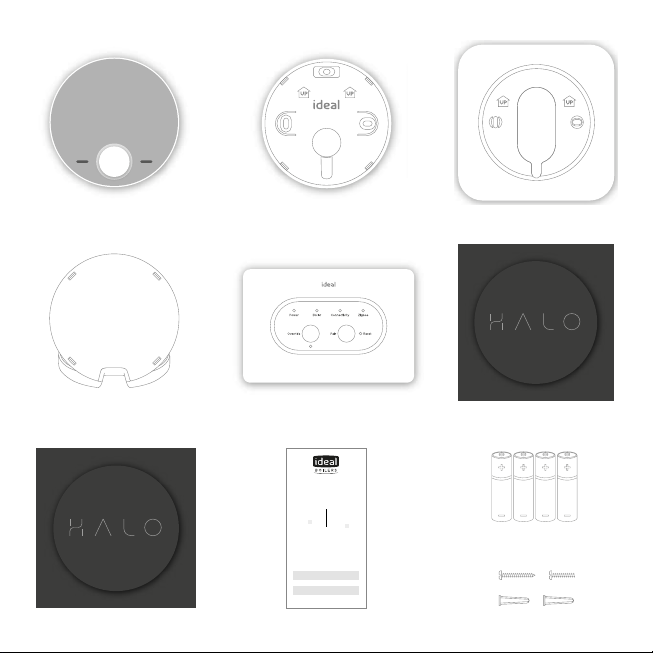
The Ideal Halo Combi RF is a wireless PRT that is
paired with the Halo Smart Interface installed in
the boiler. The Halo Smart Interface plugs into the
front aperture on the boiler and communicates
to the boiler via OpenTherm. The Halo unit is
powered by 4 AA batteries and communicates
with the Smart Interface through Zigbee, a local
RF protocol.
SAFETY INFORMATION
The Ideal Halo Combi RF must be installed by a
competent person with the appropriate safety
qualifications. Please read the instructions
carefully. Failure to follow these instructions
can damage the product or cause a hazardous
condition.
These instructions are applicable to the Ideal
Boiler models stated and must not be used with
any other make or model of boiler. This product
must be installed to all applicable standards.
Always isolate the mains supply before installing
or working on any components relating to the
boiler electronics.

8. SAP registration label 10. Screws & RawlplugsTM
6. Installation guide
7. User guide
9. 4 x AA batteries
A. KIT CONTENTS
1. Ideal Halo Combi RF
display unit
3. Trim plate
4. Desk stand 5. Smart Interface
2. Rear housing
w
w
w
.i
d
ea
l
bo
il
e
rs
.c
o
m
U
s
er
g
u
id
e
Model Name:
Halo Combi RF
Model Qualifier:
ErP Class V or ErP Class VI
I certify that this boiler is connected to a
compensation controller as indicated:
This product is compatible with the boiler
and provides compensation control that
has been permanently enabled. The boiler
has been commissioned in accordance with
the manufacturer’s instructions which have
been supplied to the householder.
The central heating temperature control
knob should normally be set in the
mid-position.
Signed:
Date:
UIN 223825 A01
Halo Combi RF
enhanced load
compensator
(Class V)
Halo Combi RF
& OS2 weather
compensator
temperature sensor
(Class VI)
w
w
w
.i
d
ea
l
bo
il
e
rs
.c
o
m
H
al
o
C
o
m
b
i
R
F
In
s
ta
ll
at
io
n
G
u
i
de

B. LOCATION
GUIDELINES
The Halo uses wireless Zigbee
communication between the
control and the Smart Interface,
up to a maximum range of 30
metres. Occasionally house
construction and materials can
reduce this communication
range and it is advisable,
where possible, to try and
avoid directing communication
through metal frames or solid
concrete walls.
If the distance between the
Halo and Smart Interface is
above 30 metres or the install
location is challenging, consider
using the Ideal Zigbee Booster
(Product Code: 221132) or
mounting the Smart Interface
externally to the boiler using
a bracket (Product Code:
220366). Further details on this
at www.idealboilers.com
1.2-1.5m
1. Mounted 1.2-1.5m above the floor 2. Not above a radiator/heat source
3. Not in direct sunlight 4. Away from any drafts
5. Not fitted behind curtains 6. Internal use only

1. The Halo can be installed with
or without the provided trim plate.
3. Insert the 4 AA batteries provided into the front
housing of the Halo. Pay close attention that the
orientation of the batteries is as indicated in the
housing.
4. Locate the front housing (display) in position
paralell to the rear housing and clip
into place.
2.
If no trim plate is required, use the rear housing
of the Halo to position the unit on the wall,
alternatively secure rear housing to trim plate.
Take care not to overtighten the screws.
C. INSTALLATION OF THE HALO
The Halo can be either wall mounted or desk mounted.
Wall mounting the Halo
If there are any concerns regarding signal strength and location of the wall mounted Halo it is advisable to
pair the control (section E) and check signal strength before fixing to the wall.

Desk mounting the Halo
1. The Halo has an integrated rear housing and desk
stand.
2. Insert the 4 AA batteries provided into the front
housing of the Halo. Pay close attention that the
orientation of the batteries is as indicated in the
housing.
3. Clip the combined rear housing and desk stand
into place.

1. Isolate mains supply to boiler.
D. INSTALLATION OF THE SMART INTERFACE
To install the Halo Smart Interface into a new boiler with serial letter code AFQ (found on the data plate)
follow the steps below. For further details on the compatibility of older boilers and how to install the
Smart Interface into a bracket and wire into the boiler please go to www.idealboilers.com
OFF
4. If an existing Opentherm device has been used,
ensure its removal and add the link wire into the
“opentherm” connection (see diagram) On brand
new boilers the link should already be in place
2. Locate the wiring terminals (230V connections
are on the left and low voltage on the right).
3. If existing 230V device is already installed
remove wiring from the 230V connections
and add the link wire into the room stat/timer
connection (see diagram). On brand new boilers
the link will already be in this position.
Link wire in
room stat/ timer
connection
230V connections
Frost stat
optional
Room stat/
timer
Mains
IN
L N
Low voltage
connections
Opentherm Weather
compensation
R
230V connections
L
Frost stat
optional
Room stat/
timer
Mains
IN
L N
Low voltage
connections
Opentherm Weather
compensation
R

7. Connect the plug on the Halo Smart Interface to
the connector in the aperture.
8. Push fit the Halo Smart Interface into
the boiler aperture.
5. Locate the blanking plate on the front of the boiler
and remove carefully with a small flat bladed
screwdriver.
6. Remove link wire plug and keep
in a safe place.
Link wire plug
Blanking
plate

10. Check the Smart Interface connection to the boiler
by pressing the Override button. The Override LED
should be green and the boiler will fire. Press the
Override button again to switch o the boiler, the
Override LED should now go out.
11. Press and hold the Pair button on the Smart
Interface until the Zigbee LED starts flashing red to
begin the pairing process with the Halo.
9. Switch on the boiler, the Halo Smart Interface will
power up and begin setup, this can take up to 90
seconds. Once setup is complete the green Power
LED should be the only LED illuminated.
ON

E. PAIRING OF THE HALO
The Halo unit now needs to be paired with the Smart Interface installed in the boiler.
Ensure the Halo Smart Interface is in pairing mode and the Zigbee LED is flashing red.
1. After the batteries are inserted, the Halo will
power up automatically.
2. The device will prompt pairing with the Halo
Smart Interface using an easy step-by-step
process.
3. Simply follow the on screen guide to select
the type of boiler and number of zones. In
this case select Combi boiler and single zone.
4. The Halo screen will show “Pairing in
Progress”, then “Synchronisation in Progress”
and then “Pairing Complete” when the Halo
has successfully connected to the Smart
Interface.
5. The device will automatically prompt set up
of the time and date.
6. There is the opportunity to add an installer
contact phone number into the device at this
stage, if not changed this will default to the
Ideal Boilers Customer Service number.
7. The home screen will be displayed showing
the current and target temperature and the
temperature bar. The Zigbee communication
icon will also be visible on the display.
8. Press and hold the Pair button on the Halo
Smart Interface until the Zigbee LED goes
from flashing red to solid green.
Pairing to smart interface in
progress, this could take a little
while
12 91
menu
Sat, 17 Nov
mode
auto
9:33pm
05
target temp
until 10:00pm
current room
temp
12 91
menu
Sat, 17 Nov
mode
auto
9:33pm
05
target temp
until 10:00pm
current room
temp
Zigbee icon

G. HALO FEATURES AND CONFIGURATION
To enter the settings menu press the menu button.
Menu options Action
Holiday Holiday mode allows the device to be switched o for a pre-defined period of
time then automatically returns to the pre-programmed heating schedule.
Timed heating schedule Set a heating schedule with up to 6 periods per day.
Support Includes information such as software version and key contact numbers.
Fault page Shows the latest fault code and fault description.
Time and date Time and date are set on power up and can be adjusted via the menu.
Advanced settings Advanced features of the device setup should be set by a competent person.
Landlord settings Specific settings for landlords.
SMART INTERFACE LED KEY
LED Status
Power Green - Power ON
No illumination - No Power
Boiler Green - Demand
No illumination - No Demand
Connectivity† No illumination - Cloud configuration not required for
Halo Combi RF
Zigbee No illumination - No Zigbee network
Green - Zigbee network active
Green flashing - Identify function
Red flashing - Pairing
Red flashing then orange - Zigbee network deletion
Orange for 30s - Factory reset
Override Green - Override active*
Green flashing - Failsafe active*
No illumination - Override OFF*
† Only applicable for Halo Combi
Wi-Fi not Halo Combi RF.
* Override and failsafe only active
when communication is lost
between Halo and Halo Smart
Interface. See Halo User Guide for
more information.

ADVANCED SETTINGS
Advanced settings should only be adjusted by a competent person, the wrong configuration can have
a detrimental eect on the thermostat and the heating system.
Description Factory setting New setting
Optimised start
Boiler starts heating in advance of schedule so heating reaches the
required temperature at the time specified.
OFF
Optimised stop
Boiler stops heating in advance of schedule so heating reaches the
required temperature at the time specified.
OFF
Delayed start
If the room temperature is close to target temperature the heating
start time is delayed to save energy.
OFF
Display tolerance
Select the display tolerance of the room temperature, this can be set
at increments of 0.5 or 0.1°C.
0.1°C
Temperature oset
Fine tune the room temperature display -2.5 to 2.5°C. 0
Daylight saving time
Automatically move to daylight saving. ON
Frost protection
The temperature that will be used to protect your home when the
thermostat is o. Can be set 5°C.
50C
Service phone number
Opportunity to input Installer contact number for service reminders.
Ideal Boilers
number

COMMISSIONING CHECKLIST
When the Halo is set up use this commissioning checklist to check and complete the install.
Description Confirmed
Use the “Identify” function to confirm successful pairing has
taken place. Short press on the Pair button on the Smart
Interface. Press Pair button again to exit “Identify” function.
Zigbee LED on Smart Interface
flashes green
Halo home screen flashes to
indicate successful pairing
Halo is positioned in the homeowners chosen location if desk mounted.
Check RSSI (Received Signal Strength Indication) of the
Zigbee wireless connection via support page on the PRT
(access via the menu).
Target RSSI between 0 and -65
and text green
On the Halo set the mode to AUTO then increase the
temperature to 30°C.
Flame ON
Boiler ON
Boiler LED on Smart Interface
ON (Green)
On the Halo set the mode to AUTO then decrease the
temperature to 5°C.
Flame OFF
Boiler OFF
Boiler LED on Smart Interface
OFF
Check the Smart Interface indication is correct. Power LED green
Zigbee LED green
Full battery level indication on Halo home screen.
Zigbee network icon is present on the Halo home screen.
Time and date correct.
Installer contact details inputted if required.
Suitable schedule has been entered for the user.
General overview of operation provided to user - refer to use guide.
Any advanced settings changes have been recorded.
Remember to leave this guide with the householder.

TROUBLE SHOOTING
No power LED on
Smart Interface
Check Smart Interface is securely plugged into boiler aperture.
Check boiler power is on.
Boiler fails to fire when
increasing target
temperature on the
Halo
Check the target temperature is above current temperature.
Check Smart Interface power LED is green.
Check Smart Interface is securely plugged into boiler aperture.
Halo screen shows
failed to pair
Check Smart Interface is in paring mode (Zigbee LED flashing red).
Check distance between Smart Interface and Halo (see section B).
Reset Smart Interface by inserting a paperclip or pen tip into reset button.
Start pairing mode again on the Smart Interface and press retry on the Halo.
If the situation persists then consider using Zigbee Booster (available separately) or
mounting the Smart Interface externally to the boiler using a bracket (further details on
www.idealboilers.com).
Halo screen shows
Replace Halo
If you have no other Halo thermostats connected to the Smart Interface or are not
replacing an existing Halo then press accept.
In the support page the
Zigbee RSSI is lower
than -65 and text red
Consider moving the Halo closer to the Smart Interface.
If the situation persists then consider using Zigbee Booster (available separately) or
mounting the Smart Interface externally to the boiler using a bracket (further details on
www.idealboilers.com).
Deleting Halo from the
Zigbee Network
On the Halo press the dial and the right hand key together for 15 seconds, this will delete
the Halo from the Zigbee network and factory reset the device.
Deleting Zigbee
Network
To delete all devices from the Zigbee network, press and hold the Pair button on the Halo
Smart Interface. The Zigbee LED on the Smart Interface will flash red then orange to
confirm the devices have been deleted from the network.
Factory reset of the
Halo Smart Interface
Press and hold the Pair button and the Override button for 20 seconds.
The Halo Smart Interface will delete all Zigbee devices from the network, this will take
approximately 20 seconds. On disconnection, the Smart Interface will automatically
begin the setup process as per section D6 of the installation guide.

www.idealboilers.com | welcome to our ideology
Hereby, Ideal Boilers Ltd declares that this device (model 222140) is in
compliance with: Directive 2014/53/EU.
The full text of the EU declaration of conformity is available at the
following internet address www.idealboilers.com
UIN: 223827 A02
Ideal Boilers Ltd
National Avenue
Hull, HU5 4JN
T: 01482 498660
RF frequency: 2405 –2480MHz
Max. RF output power: 10dBm
Other manuals for Halo Combi RF
1
This manual suits for next models
1
Table of contents
Other IDEAL Thermostat manuals

IDEAL
IDEAL RF Electronic User manual

IDEAL
IDEAL LOGIC COMBI User manual

IDEAL
IDEAL Touch User manual

IDEAL
IDEAL Vogue S15 User manual

IDEAL
IDEAL RF Electronic User manual

IDEAL
IDEAL LOGIC+ Combi 24 User manual

IDEAL
IDEAL Touch User manual

IDEAL
IDEAL Touch Logic Combi C User manual

IDEAL
IDEAL Halo Combi Wi-Fi User manual

IDEAL
IDEAL Halo Combi RF User manual