manuals.online logo
Brands
  1. Home
  2. •
  3. Brands
  4. •
  5. OJ Electronics
  6. •
  7. Thermostat
  8. •
  9. OJ Electronics ETN4-1999 User manual

OJ Electronics ETN4-1999 User manual

© 2011 OJ Electronics A/S
1
Contents
MCS4-10 / MSD4-1999 / MSA4-10
67097 07/11 (MBC)
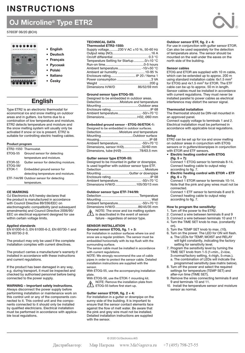
Thermostat ETN4-1999
English
MANUAL
Introduction ................................................................................ 1
Thermostat operation .............................................................. 1
Temperature setting .................................................................. 1
Settings ...................................................................................... 1
Max. temperature .................................................................... 2
Min. temperature ..................................................................... 2
Max. limit temperature ............................................................. 2
Min. limit temperature .............................................................. 2
Frost protection ....................................................................... 2
Night setback / energy-saving function ................................... 2
Measured floor temperature .................................................... 2
Measured room temperature ................................................... 2
Application ............................................................................... 2
Scale ........................................................................................ 2
Temperature reading ................................................................ 2
Oset ....................................................................................... 2
Control method ........................................................................ 2
PWM cycle time ....................................................................... 2
Dierential temperature ........................................................... 2
Backlighting ............................................................................. 2
Relay function .......................................................................... 2
Program version ...................................................................... 2
Child lock .................................................................................. 2
Control signal ............................................................................. 2
Factory settings ......................................................................... 2
Error messages ......................................................................... 3
Introduction
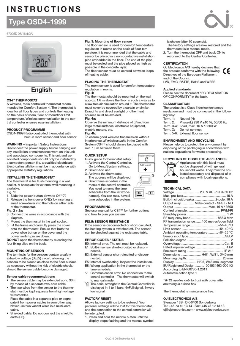
ETN4-1999 is an all-in-one thermostat for DIN-rail mounting in an
approved cabinet. It covers the needs of a variety of applications
in which maximum comfort and minimum energy consumption are
required, e.g. electric floor heating, frost protection, ice and snow
melting, cooling, etc. The thermostat allows a required temperature
to be set within the range -19.5 to +70°C. The large backlit display
provides a clear view of status, while the three navigation buttons
allow easy menu operation.
1234567
8 9 10 11 12 13 14
All-in-one Thermostat
Centremost
button
Programming
ON/OFF
switch
Left-hand button
Lower tempera-
ture
Right-hand
button
Raise tempera-
ture
ETN4-1999 THERMOSTAT
Thermostat operation
The ON/OFF button is used to turn the thermostat o “0” or on “I”.
When the ON/OFF switch is in position “0”, the relay is deactivated.
All settings are saved.
The thermostat is easily operated using the navigation buttons.
Basic functions like temperature and thermostat settings are sim-
ple to perform. Whenever a button is pressed, the backlighting will
come on and stay lit for 30 seconds after a button is last pressed.
Temperature setting
The thermostat has a temperature setting range of -19.5 to +70°C.
The menu allows limits to be defined for the range within tempera-
ture may be set (factory setting = 0-40°C).
The required temperature
is set using the left- or right-hand button. The temperature setting
flashes on the display. Five seconds after the setting has been made,
the required temperature will be shown on the display continuously.
Settings
To set parameter values, press and hold the centremost button for
three seconds. SCA  Hi  40 will appear on the display. Firstly,
SCA will be displayed for 1 second, followed by Hi, and finally 40.
The required value can now be set using the navigation buttons. To
access the next parameter, press the programming button again.
If no button is pressed for 30 seconds, the program returns to the
initial display.
2© 2011 OJ Electronics A/S
ETN4-1999 English
controlled via an external signal (fig. 3 in instructions).
Example: The setpoint is 25°C.
Energy-saving function = -5°C means temp. setting = 20°C.
Energy-saving function = +3°C means temp. setting = 28°C.
Measured floor temperature
Displays actual floor temperature (if a floor sensor is fitted).
Measured room temperature
Displays actual room temperature.
Application
Sets thermostat function. Select the required control type. Four
alternatives exist:
Floor (F): The thermostat controls floor temperature
alone.
A floor sensor must be fitted.
Room (A): The thermostat controls room temperature
alone.
Room/limit (AF): The thermostat controls room temperature
while respecting min. and max. limits for floor
temperature. A floor sensor must be fitted.
Regulator (C): The thermostat functions as a simple regulator
and no sensors are used. The setting is in per
cent.
Scale
Choose between degrees Celsius and a numerical scale. If the
numerical scale is selected, temperature is set on a scale from
0.0 to 10.0 where 0.0 corresponds to min. temperature (SCA Lo)
and 10.0 corresponds to max. temperature (SCA  Hi).
Temperature reading
Defines which temperature is to be shown on the start display: the
setpoint (SP) or the actual, measured temperature.
Offset
If the actual temperature (measured using a thermometer) diers
from that displayed by the thermostat, the thermostat can be
adjusted to oset the dierence.
Control method
PWM or ON/OFF control can be selected. PWM is an advanced
control method which calculates the most eective and economi-
cal way to heat homes and other buildings. ON/OFF control is
traditional dierential control (e.g. 0.3°C) for other tasks.
PWM cycle time
Allows cycle time to be set when using PWM control. At least 20
min is recommended.
Differential temperature
Allows temperature dierential to be set when using ON/OFF con-
trol. The higher the dierential temperature, the lower the number
of relay operations.
Relay function
When used for heating purposes, the relay should be in normally
open position (NO). If the thermostat is used for cooling purposes,
the relay should be turned to normally closed (NC).
Software version
Displays thermostat software version.
Child lock
Allows thermostats in public and other places to be locked, thus
preventing unauthorised alteration of the settings. Press and hold
the left- and right-hand buttons simultaneously for 10 seconds. A
symbol indicates that the thermostat is locked.
The child lock can be released by pressing the left- and right-hand
buttons simultaneously for 10 seconds.
Factory settings
Allows factory settings to be restored. Your personal settings will
be deleted from the thermostat.
Parameter Shown on display Factory settings
Max. temperature SCA  Hi  40 40°C
(-19.5/+70°C)
Min. temperature SCA  Lo  0 0°C
(-19.5/+70°C)
Max. limit temperature
FLOOR *1 Li  Hi  28 28°C
(-19.5/+70°C + OFF)
Min. limit temperature
FLOOR *1 Li  Lo  15 15°C
(-19.5/+70°C + OFF)
Frost protection dEF  8.0 8°C
(0/+10°C)
Night setback nSb  -5.0 -5°C
(-19.5/+30°C)
Measured floor tem-
perature FLo  24.5 (example) *4
Measured room
temperature ro  21.5 (example) *4
Application APp  F (Floor sensor)
 A (Room sensor)
 AF (Room sensor with
floor temperature
limits)
 C : Regulator
F : Floor
Scale LCd  C C = Celsius
(nU = numerical)
Temperature reading in
start display dF  SP SP = Setpoint
(tP = actual temp.)
Oset OFF  0 0
(+/- 10°C)
Control method PWM  On On
(OFF)
PWM cycle time *2 cyc  20 20 minutes
(10-60 min)
Dierential tempera-
ture *3 dIF  0.3 0.3°C
(0.3/10°C)
Relay function rEL  no
no = normally open
(nc = normally
closed)
Software version SU  1.0
*1 : Only available if APp  AF is selected under Application.
*2 : Only available if PWM is ON under Control Method.
*3 : Only available if PWM is OFF under Control Method.
*4 : With no or disconnected sensor, - - is shown on the display.
If Regulator (C) is selected under Application, the floor and room sensors are discon-
nected and heating is controlled on a scale of 0-10, corresponding to 0-100% of full
power.
Max. temperature
The highest temperature to which the thermostat can be set.
Min. temperature
The lowest temperature to which the thermostat can be set.
Max. limit temperature
Allows the highest permissible floor temperature to be set for
wooden and other floor types when control type has been set to
room sensor with floor limit (AF).
Min. limit temperature
Allows the lowest permissible floor temperature to be set for tiled
and other floor types when control type has been set to room sen-
sor with floor limit (AF).
Frost protection
The lowest temperature for frost protection when the function is
activated via an external signal (fig. 4 in instructions).
Example: The setpoint is 25°C.
Frost protection = 8°C means temp. setting = 8°C.
Night setback / energy-saving function
The number of degrees the temperature setting is to be reduced.
The night setback setting must be preceded by a minus sign (-). Is
© 2011 OJ Electronics A/S 3
Press and hold the centremost button for 10 seconds. The display
is switched o and then on again. Application is shown on the
display (APp F) followed by the temperature setting.
Error messages
If a fault occurs, the master/thermostat will display one of the fol-
lowing error codes:
Error code Fault Remedy
E0 Internal fault. Thermostat defective. Replace thermostat.
E1 External room sensor defective or short-
circuited (terminals 10-11).
Replace sensor/sensor cable. To continue to operate the system without
sensor, set control type to Regulator under Application (APp C).
E2 External floor sensor defective or short-circuited
(terminals 8-9).
Replace sensor/sensor cable. To continue to operate the system without
sensor, set control type to Regulator under Application (APp C).
E5 Internal overheating. Thermostat shuts o heat-
ing.
Check installations. Check that heating cables are not overloaded or
that ambient temperature is excessive. When internal temperature drops,
the thermostat automatically reactivates.
ETN4-1999 English
INSTRUCTIONS
1
© 2011 OJ Electronics A/S
67096A 10/11 (MBC)
Type ETN4-1999
English
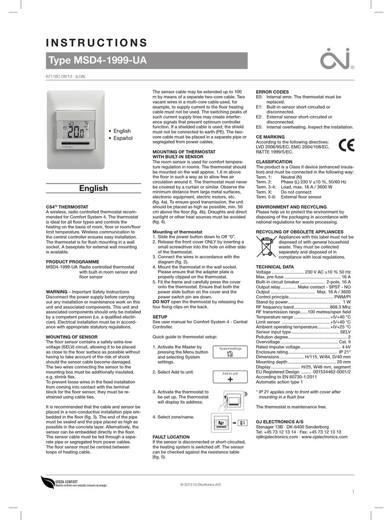
The ETN4-1999 All-in-one is an electronic on/
o thermostat for 1 or 2 NTC sensors located
externally.
An All-in-one thermostat for many application
types:
• Electrical floor heating
• Frost protection
• Ice and snow melting
• Cooling
The thermostat should be DIN rail mounted.
A floor sensor is supplied.
PRODUCT PROGRAMME
ETN4-1999 Thermostat incl. floor sensor
ETF-944/99-H Remote room sensor
ETNK Wall box for ETN4-1999
MM-7595 Electronic day/week timer
WARNING – Important Safety Instructions.
Disconnect the power supply before carrying
out any installation or maintenance work on this
control unit and associated components. This
control unit and associated components should
only be installed by a competent person (i.e. a
qualified electrician). Electrical installation must
be in accordance with appropriate statutory
regulations.
NOTE: Use philips PH2 or slotted 4x0.8 mm
screwdriver. Screws must be tightened with a
torque of 1,0 Nm.
MOUNTING OF SENSORS
The 2 sensors contain a safety extra-low volt-
age (SELV) circuit, allowing the sensors to be
placed as close to the floor surface as neces-
sary without the risk of electric shock, should
the sensor cable become damaged. The two
wires from the sensor to the thermostat must be
separated from high voltage wires/cables.
The sensor cable may be extended up to 100
m by means of a separate two-core cable. The
two-core cable must be placed in a separate
pipe or segregated from power cables. Two
vacant wires in a multi-core cable used for
example to supply current to the floor heating
cable must not be used. The switching peaks of
such current supply lines may create interfer-
ence signals that prevent optimum controller
function. If a shielded cable is used, the shield
must not be connected to earth (PE).
Floor sensor
It is recommended that the cable and sensor be
placed in a non-conductive installation pipe em-
bedded in the floor (fig. 2). The end of the pipe
must be sealed and the pipe placed as high as
possible in the concrete layer. Alternatively, the
sensor can be embedded directly in the floor.
The sensor cable must be led through a sepa-
rate pipe or segregated from power cables.
The floor sensor must be centred between the
heating cable.
Room sensor
The room sensor is used for comfort tempera-
ture regulation in rooms. The sensor should be
mounted on the wall approx. 1.6 m above the
floor in such a way as to allow free air circula-
tion around it. Draughts and direct sunlight or
other heat sources must be avoided (fig. 5).
INSTALLATION OF THERMOSTAT
ETN4-1999 should be DIN rail mounted. To
cover the terminals, use ETNK wall box. The
mains, load and sensor cables should be con-
nected as shown in fig. 1+2.
To prevent loose cables from the fixed instal-
lation from coming into contact with the
terminal block for the floor sensor, they must be
restrained using cable ties.
NIGHT SETBACK / FROST PROTECTION
The ETN4-1999 has 2 inputs for night setback
and frost protection. See fig. 3+4. Do not use
night setback and frost protection at the same
time.
POWER UP
To turn on the ETN4-1999 thermostat, push the
power slide button up to On “I”. The backlit dis-
play will briefly show the application and then
the set temperature.
PROGRAMMING
See ETN4-1999 user manual.
FAULT LOCATION
If the sensor is disconnected or short-circuited,
the heating system is switched o. The sensor
can be checked against the resistance table
(fig. 6).
ERROR CODES
E0: Internal error. The thermostat must be
replaced.
E1: External room sensor short-circuited or
disconnected (terminal 10-11).
E2: External floor sensor short-circuited or
disconnected (terminal 8-9).
E5: Overheating. The temperature is too high in
the thermostat and the heating is switched
o.
CE MARKING
According to the following standard:
LVD/EMC: EN 60730-2-9.
CLASSIFICATION
The product is a Class II device (enhanced
insulation) and must be connected in the follow-
ing way:
Term. 1: Line (L1) 230 V ±10%, 50/60 Hz
Term. 2: Neutral (L2/N)
Term. 3: Output for control, max. 100mA
Term. 4–5: Load, max. 16 A / 3600 W
Term. 6: Input, night setback (S)*
Term. 7: Input, frost protection ( )*
Term. 8-9: External floor sensor (SELV)
Term. 10-11: External room sensor (SELV)
Term. X: Do not connect
* Do not use night setback and frost protection
at the same time.
ENVIRONMENT AND RECYCLING
Please help us to protect the environment by
disposing of the packaging in accordance with
national regulations for waste processing.
RECYCLING OF OBSOLETE APPLIANCES
Appliances with this label must not
be disposed of with general
household waste. They must be
collected separately and disposed
of in compliance with local
regulations.
TECHNICAL DATA
Voltage .................... 230 VAC ±10% 50/60 Hz
Max. pre-fuse .............................................16 A
Built-in circuit breaker .................. 2-pole, 16 A
Output relay .......... Make contact - SPST - NO
Output .............................. Max. 16 A / 3600 W
Control principle ............... ON/OFF or PWM/PI
Sensor type ....NTC (12kOhm) 3 m/max. 100 m
Stand-by power ...................................... 0.5 W
Control temperature range ............ -19,5/+70°C
Limit sensor .................................-19,5/+70°C
Ambient operating temperature * .....-20/+55°C
Night Setback relative ................... -19,5/+30°C
Night Setback regulator .......................0-100%
Frost protection, absolute ..................... 0-10°C
Frost protection regulator, relative ......0-100%
Control pollution degree ................................ 2
Rated impulse voltage .............................. 4 kV
Enclosure rating ....................................... IP 20
Automatic action .......................................... 1B
Dimensions ................ H/86, W/52,5, D/58 mm
DIN module size .....................................3xM36
Display ........ H/25, W/38 mm. segment backlit
* At very low ambient temperatues the display
may respond slowly.
The thermostat is maintenance free.
FIGURES
Located on page 2.
Fig. 1: ETN4-1999 terminal overview
Fig. 2: Application with floor and room sensor
Fig. 3: Night setback connection
Fig. 4: Frost protection connection
Fig. 5: Mounting room sensor
Fig: 6: Sensor resistance table
OJ ELECTRONICS A/S
Stenager 13B · DK-6400 Sønderborg
Tel: +45 73 12 13 14 · Fax: +45 73 12 13 13
[email protected] · www.ojelectronics.com
• English
• Deutsch
• Русский
4 The trademark is registered and belongs to OJ Electronics A/S · © 2011 OJ Electronics A/S
BR929A08
Sensor
Temp.(˚C) Value (ohm)
-10
0
10
20
30
64000
38000
23300
14800
9700
Fig. 6Fig.5
BR-0991-A04b
Fig.1 Fig.2 Fig.3
Fig.4
OJ ELECTRONICS A/S
Stenager 13B · DK-6400 Sønderborg
Tel: +45 73 12 13 14 · Fax: +45 73 12 13 13
[email protected] · www.ojelectronics.com
ROOM SENSOR

Other manuals for ETN4-1999

7

Other OJ Electronics Thermostat manuals

OJ Electronics OCD4 Installation and operation manual

OJ Electronics

OJ Electronics OCD4 Installation and operation manual

OJ Electronics OJ Microline ICD3-1999 User manual

OJ Electronics

OJ Electronics OJ Microline ICD3-1999 User manual

OJ Electronics OCC4 User manual

OJ Electronics

OJ Electronics OCC4 User manual

OJ Electronics MCC4 User manual

OJ Electronics

OJ Electronics MCC4 User manual

OJ Electronics PISTESARJAT Microtemp MCD5 User manual

OJ Electronics

OJ Electronics PISTESARJAT Microtemp MCD5 User manual

OJ Electronics MWD5-1999-OJC3 User manual

OJ Electronics

OJ Electronics MWD5-1999-OJC3 User manual

OJ Electronics OCD2-1999 User manual

OJ Electronics

OJ Electronics OCD2-1999 User manual

OJ Electronics UWG4 User manual

OJ Electronics

OJ Electronics UWG4 User manual

OJ Electronics MWD5-1999-UAC3 User manual

OJ Electronics

OJ Electronics MWD5-1999-UAC3 User manual

OJ Electronics ETR2 User manual

OJ Electronics

OJ Electronics ETR2 User manual

OJ Electronics 29071 User manual

OJ Electronics

OJ Electronics 29071 User manual

OJ Electronics ETN4-1999 User manual

OJ Electronics

OJ Electronics ETN4-1999 User manual

OJ Electronics OCD6-1999 User manual

OJ Electronics

OJ Electronics OCD6-1999 User manual

OJ Electronics ETN4-1999 User manual

OJ Electronics

OJ Electronics ETN4-1999 User manual

OJ Electronics MTD2 User manual

OJ Electronics

OJ Electronics MTD2 User manual

OJ Electronics Microline OTN Series User manual

OJ Electronics

OJ Electronics Microline OTN Series User manual

OJ Electronics OCC4 User manual

OJ Electronics

OJ Electronics OCC4 User manual

OJ Electronics ETN4-1999 User manual

OJ Electronics

OJ Electronics ETN4-1999 User manual

OJ Electronics ETN4-1999 User manual

OJ Electronics

OJ Electronics ETN4-1999 User manual

OJ Electronics ETV Series User manual

OJ Electronics

OJ Electronics ETV Series User manual

OJ Electronics OCC2-1991H1 User manual

OJ Electronics

OJ Electronics OCC2-1991H1 User manual

OJ Electronics OCD6-1999 User manual

OJ Electronics

OJ Electronics OCD6-1999 User manual

OJ Electronics MSW4-10 User manual

OJ Electronics

OJ Electronics MSW4-10 User manual

OJ Electronics ADG4 User manual

OJ Electronics

OJ Electronics ADG4 User manual

Popular Thermostat manuals by other brands

HAI Omnistat RC-81 installation manual

HAI

HAI Omnistat RC-81 installation manual

Salus ERT50T Triac instruction manual

Salus

Salus ERT50T Triac instruction manual

Theben RAMSES 725 operating instructions

Theben

Theben RAMSES 725 operating instructions

Watts Tekmar WiFi Thermostat 561 user manual

Watts

Watts Tekmar WiFi Thermostat 561 user manual

hager EK053 User instructions

hager

hager EK053 User instructions

Mitsubishi Electric RMF-CA200-V2 Installation instructions manual

Mitsubishi Electric

Mitsubishi Electric RMF-CA200-V2 Installation instructions manual

Vaillant VRT 50 OPERATING AND INSTALLATION Manual

Vaillant

Vaillant VRT 50 OPERATING AND INSTALLATION Manual

HRT 6018 quick start guide

HRT

HRT 6018 quick start guide

Honeywell RTHL3550 Quick installation guide

Honeywell

Honeywell RTHL3550 Quick installation guide

Siemens RDG140 quick start guide

Siemens

Siemens RDG140 quick start guide

Vive Comfort TP-P-725 installation manual

Vive Comfort

Vive Comfort TP-P-725 installation manual

Crestron CHV-TSTAT-FCU-PIR-10 Supplemental guide

Crestron

Crestron CHV-TSTAT-FCU-PIR-10 Supplemental guide

Sabiana 9060134 instruction manual

Sabiana

Sabiana 9060134 instruction manual

Salus ST320 instruction manual

Salus

Salus ST320 instruction manual

VLM HP-2F operating manual

VLM

VLM HP-2F operating manual

Vimar SMART CLIMA manual

Vimar

Vimar SMART CLIMA manual

Lux Products CAG111 Series Installation and operating instructions

Lux Products

Lux Products CAG111 Series Installation and operating instructions

One Hour Comfort Sentry OH-522 Installation and operating instructions

One Hour

One Hour Comfort Sentry OH-522 Installation and operating instructions

manuals.online logo
manuals.online logoBrands
  • About & Mission
  • Contact us
  • Privacy Policy
  • Terms and Conditions

Copyright 2025 Manuals.Online. All Rights Reserved.