elv WS 200 User manual

Operating Instructions
Weather station
„WS 200“
ELV Elektronik AG · PF 1000 · D-26787 Leer
Telefon 0491/6008-88 · Telefax 0491/6008-244

2
These operating instructions belong with this product. They contain important information
for putting it into service and operating it. This should be noted also when this product is
passed on to a third party.
Therefore look after these operating instructions for future reference!
A list of contents with the corresponding page numbers can be found in the index on page 44.

3
Introduction
Dear Customer,
Thank you for purchasing this product.
The product has been EMV-tested and thus meets the requirements of the valid European
and national guidelines. CE-conformity has been proven and the corresponding declarations
deposited with the manufacturer.
In order to maintain this condition and ensure safe operation, you, as the user, have to observe
this operating manual.
Prior to using the product for the first time, please read the entire operating manual and observe
all operating and safety instructions.
We should already like to point out now the correct order for commissioning the
products. Please also observe the installation and calibration instructions in this
operating manual as well as the information about impairment of radio transmission
between the sensors and base station.
All company names and product descriptions listed herein are the trademarks of the
respective manufacturers. All rights are reserved.

4
Table of Contents
Page
1. Intended Use ................................................................................................................... 6
2. Scope of Delivery ............................................................................................................ 6
3. Explanation of Symbols ................................................................................................. 7
4. Features and Functions ................................................................................................. 7
a) Base Station ................................................................................................................ 7
b) Multipurpose Sensor .................................................................................................. 9
c) Outdoor Sensor .......................................................................................................... 9
5. Safety Instructions ......................................................................................................... 9
6. Battery and Accumulator Information ....................................................................... 10
7. Preparation and Start-up ............................................................................................. 11
a) Start-up of the Multipurpose Sensor ....................................................................... 11
b) Start-up of Other Sensors ........................................................................................ 14
c) Start-up of the Base Station ..................................................................................... 14
d) Log-In of Sensors during Operation ......................................................................... 15
8. Indications of the LC Display ...................................................................................... 16
9. Configuration and Operation ...................................................................................... 18
a) Basic Settings, Configuration ................................................................................... 18
Calling-up the configuration mode ........................................................................... 19
Setting the date and time ......................................................................................... 19
Entering degrees of latitude and longitude .............................................................. 20
Setting the time zone ................................................................................................ 21
Assigning the march indication ................................................................................ 21
Selecting the unit for the temperature indication .................................................... 22
Selecting the unit for the wind speed ...................................................................... 22
Exiting the configuration mode ................................................................................ 22
b) Operation .................................................................................................................. 23
Selecting the indoor temperature ............................................................................. 23
Selecting the outdoor temperature .......................................................................... 23
Selecting the outdoor sensor ................................................................................... 23
Indicating the MIN/MAX values ................................................................................ 23
Indicating the time/date for the single extreme value ............................................. 24
Deleting the MIN/MAX values ................................................................................... 25
Setting the contrast of the LC display ..................................................................... 25

5
Page
c) Further Functions ...................................................................................................... 26
Indication of the moon phases ................................................................................. 26
Weather Willi ............................................................................................................. 26
Weather forecast....................................................................................................... 26
Wind symbol indication (wind cone) ........................................................................ 27
Comfort indicator ...................................................................................................... 27
Frost warning ............................................................................................................ 27
Storm warning ........................................................................................................... 27
10. Replacing the Battery .................................................................................................. 28
a) Base Station .............................................................................................................. 28
b) Multipurpose Sensor, Outdoor Sensors .................................................................. 28
11. Troubleshooting ............................................................................................................ 29
12. Coverage ........................................................................................................................ 31
13. Maintenance and Cleaning .......................................................................................... 32
a) General ...................................................................................................................... 32
b) Cleaning the Base Station ........................................................................................ 32
c) Cleaning the Multipurpose Sensor and the Outdoor Sensors ................................ 33
14. Handling ......................................................................................................................... 34
a) General ...................................................................................................................... 34
b) Base Station .............................................................................................................. 34
c) Multipurpose Sensor ................................................................................................ 34
15. Explanation of Terms ................................................................................................... 35
16. Disposal ......................................................................................................................... 37
a) General ...................................................................................................................... 37
b) Disposal Instructions for Batteries/Accumulators ................................................... 37
17. Technical Data .............................................................................................................. 38
18. Position Table (Latitude and Longitude Degrees) .................................................... 39
19. Brief Instructions .......................................................................................................... 40

6
1. Intended Use
The Weather Station WS 200 is a high-quality universal weather measuring system which is able
to process a large number of weather data and additional information and can indicate both
current values and forecasts.
All relevant data are simultaneously presented on the LC display, further data can be indicated
by pressing a key.
A special feature is the figure of the ”Weather Willi”. The clothes he wears show the current
outdoor temperature range, his hair and scarf reflect the range of the current wind speed and
his umbrella indicates prognosticated rain.
The forecasts of the basis station are to be considered orientation values. They do not represent
an absolutely accurate prognosis. The manufacturer does not take over any responsibility for
incorrect indications, measured values or weather forecasts and the consequences thereof.
This product is designed for private use and is not suitable for medical purposes or for informing
the public.
The components of this product are not a toy, they contain fragile glass and ceramic parts.
Set up all the components in such a manner that they are out of the reach of children.
The product is operated by batteries. All external sensors transmit their data to the base station
via radio in the range of 868 MHz (coverage up to 100m in the free field).
Use other than that described above will lead to damage to the product.
Please read the complete operating instructions before use. They contain important
information for correct installation, functioning and operation.
2. Scope of Delivery
•Weather Station WS 200
•Plastic foot for the weather station
•Multipurpose sensor KS 200
•Mounting rod for the multipurpose sensor
•Specially shaped aluminium part for installing the mounting rod
•Hose band clip
•Operating instructions

7
3. Explanation of Symbols
The symbol with the lightening in the triangle is used when your health is at risk, e.g.
through an electric shock
An exclamation mark in a triangle indicates important information in these operating
instructions which must be observed without fail.
The ”hand” symbol can be found when you are to be given tips and information on
operation.
4. Features and Functions
a) Base Station
Indication of indoor temperature and air humidity
•temperature indication in °C or °F / air-humidity indication in % rH (% relative air humidity))
•can be switched to the indication of the inside dew point
•storage of minimum/maximum temperatures with the corresponding times/dates of
measurement
•storage of minimum/maximum air humidity with the corresponding times/dates of measurement
•Climatic comfort zone indicator
•graphical representation of the march of temperature over the last 24 hours
Indication of an outdoor sensor (temperature and air humidity)
•indication of the data of the multipurpose sensor or of the 8 outdoor sensors for temperature/
air humidity
•optional indication of temperature, dew point or perceived temperature (windchill)
•storage of minimum and maximum temperatures with the corresponding times/dates of
measurement
•storage of minimum and maximum air humidity with the corresponding times/dates of
measurement
•Graphical representation of the march of temperature over the last 24 hours
Indication of wind speed
•wind speed indication with selectable units: km/h, m/s, mph
•storage of the maximum wind speed values with the corresponding times/dates of measurement
•additional graphical representation (wind cone) for light, moderate and strong winds

8
Indication of the march of air pressure/indication of the tendency of
air pressure
•graphical representation of the pressure march over the last 24 hours
•storage of the minimum and maximum air pressure values with the corresponding times/
dates of measurement
•indication of the tendency of air pressure in 5 different steps: strongly increasing, increasing,
unchanging, decreasing, strongly decreasing
Symbol indication of the weather forecast
•symbols for: rainy, cloudy, bright, sunny
Indication of time and date
•integrated quartz clock
Indication of sunrise and sunset
•based on the locations which are to be entered individually, a calculation is possible in the
range from -60°N to +60°N
Indication of the phases of the moon
•indication of the current phase of the moon in 8 steps: new moon, waxing moon, full moon,
waning moon (with intermediate steps)
Warning functions
•frost warning for a temperature decreasing below 4°C (symbol: ice crystal)
•storm warning for a sharp air pressure decrease within a short period of time (symbol: danger
sign)
”Weather Willi” weather indicator
Following the almost forgotten weather house, in which a person with an umbrella steps out of
the door in case of bad weather and a person lightly dressed appears in case of good weather,
the WS 200 is provided with the ”Weather Willi”.
The behaviour of this figure depends on various weather factors so that you can see at a glance
which dressing you should put on if you want to go outside.
This indicator does not only reflect the current measured values for outdoor temperature, air
humidity and wind, but also the weather forecast data.
Therefore, many different presentations and kinds of clothing of ”Weather Willi” are
provided and shown according to the weather situation.
•The clothing of ”Weather Willi” depends on the outdoor temperature measured at the
multipurpose sensor and ranges from swimming shorts up to the complete winter dressing
including a cap, a muffler and gloves.
•At wind speeds higher than 20 km/h (moderate wind) the hair of ”Weather Willi” blow in the
wind and if he has put a muffler on – dependent on the temperature, too – it also blows in the
wind.
•If the weather forecast predicts rain, the ”Weather Willi” will take his umbrella with him.

9
b) Multipurpose Sensor
•Radio transmission of:
-wind speed
-temperature
-air humidity
C) Outdoor Sensor
•Radio transmission of:
-temperature
-air humidity
5. Safety Instructions
The warranty will lapse for damage due to non-compliance with these operating
instructions. We shall not be held liable for any consequential damage or loss!
We shall not accept liability for damage to property or personal injury caused
by incorrect handling or non-compliance with the safety instructions. Any claim
to warranty will lapse in such cases.
Dear Customer, the following safety and risk instructions are intended not only for the
protection of your health but also for the protection of the device. Please read through the
following points attentively:
Do not use this product in hospitals or medical institutions. The outdoor sensor does only emit
relatively weak radio signals. These radio signals could, however, lead to malfunctions in life-
supporting systems. The same may possibly apply to other areas.
The weather station is only designed for dry rooms. Do not expose it to direct sunlight, high
temperatures, coldness or excessive dampness and humidity.
The multipurpose sensor (and separately/additionally available outdoor sensors) is suitable for
operation in non-protected outdoor areas.
For safety and licensing (CE) reasons, unauthorised conversion of and/or modifications to the
product are not permitted.
Do not leave packaging material lying around carelessly. Plastic foil/bags and polystyrene parts
etc. could become dangerous toys for children.
Handle the product with care. It can be damaged through impact, blows or by being dropped
even from a low height.

10
6. Battery and Accumulator Information
•Batteries/accumulators must be kept out of the reach of children.
•Make sure that the batteries/accumulators are inserted with the correct polarity.
•Do not leave the batteries/accumulators lying around in the open; there is a risk of their being
swallowed by children or domestic animals. If swallowed, immediately contact a doctor.
•Leaking or damaged batteries/accumulators can cause burning if they come into contact with
the skin. For this reason you should use suitable protective gloves.
•Make sure that batteries/accumulators are not short-circuited or thrown into a fire. There is
a risk of explosion!
•Never dismantle batteries/accumulators!
•Batteries may not be recharged. There is a risk of explosion!
•In case of longer periods of non-use (e.g. during storage) remove the inserted batteries/
accumulators to avoid damage by a leaking battery/accumulator.
•Always replace the whole set of batteries/accumulators. Do not mix batteries/accumulators
of different types/manufacturers.
•Never mix batteries with accumulators!
Please note:
The weather station, multipurpose sensor and possibly used outdoor sensors can be
operated by accumulators. However, due to the lower voltage of accumulators
(accumulator = 1.2 V, battery = 1.5 V) the operating life can be decreased. Moreover,
the radio coverage will be reduced, in rare cases even malfunctions can be caused.
Therefore, the following rule applies:
If you face any problem during the operation based on accumulators, use batteries
instead of them. We recommend you to operate the weather station, multipurpose
sensor and possibly existing outdoor sensors only with high-quality alkaline batteries.
Please refer to chapter 16 for the environmental-friendly disposal of batteries
and accumulators.
11
7. Preparation and Start-up
Please note:
First start up all provided sensors (multipurpose sensor and possibly existing
outdoor sensors) (insert batteries) before starting up the weather station itself.
If you fail to follow this order of proceeding, it may be that the base station is
not able to identify the provided sensors!
It is principally recommended to test the base station with all its sensors (supplied multipurpose
sensor and possibly existing outdoor sensors) first in a room, before installing the sensors
outside.
The distance between the base station and the sensors must be at least 2m to avoid
interference. Do not place the sensors side by side, but install them throughout the
area (e.g. if you have purchased several additional sensors).
If you find out that one of the sensors is not received after the installation, you can take it for
granted that the radio reception is too weak.
You avoid complex and time-consuming troubleshooting, if you perform this first functional test.
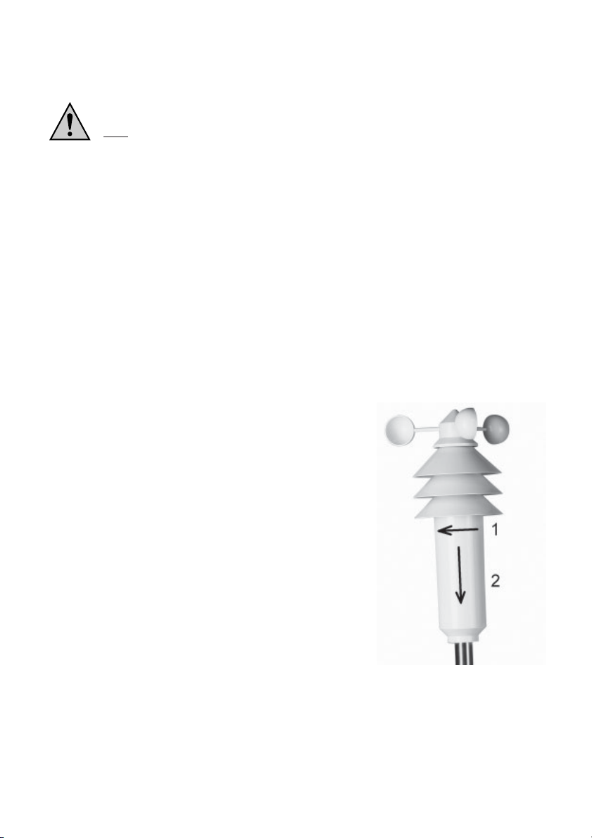
a) Start-up of the Multipurpose Sensor
•Open the housing of the multipurpose sensor. First, turn
the lower cover of the housing a little bit towards the arrow
as shown on the right (1) and then pull it carefully
downwards (2).
•There are two options to mount the sensor on a mast:
1. Own installation mast, e.g. purchased in the DIY
superstore
2. Optionally available installation mast matched to the
system (not included in the scope of delivery, is to be
ordered separately)
Fig. 1
12
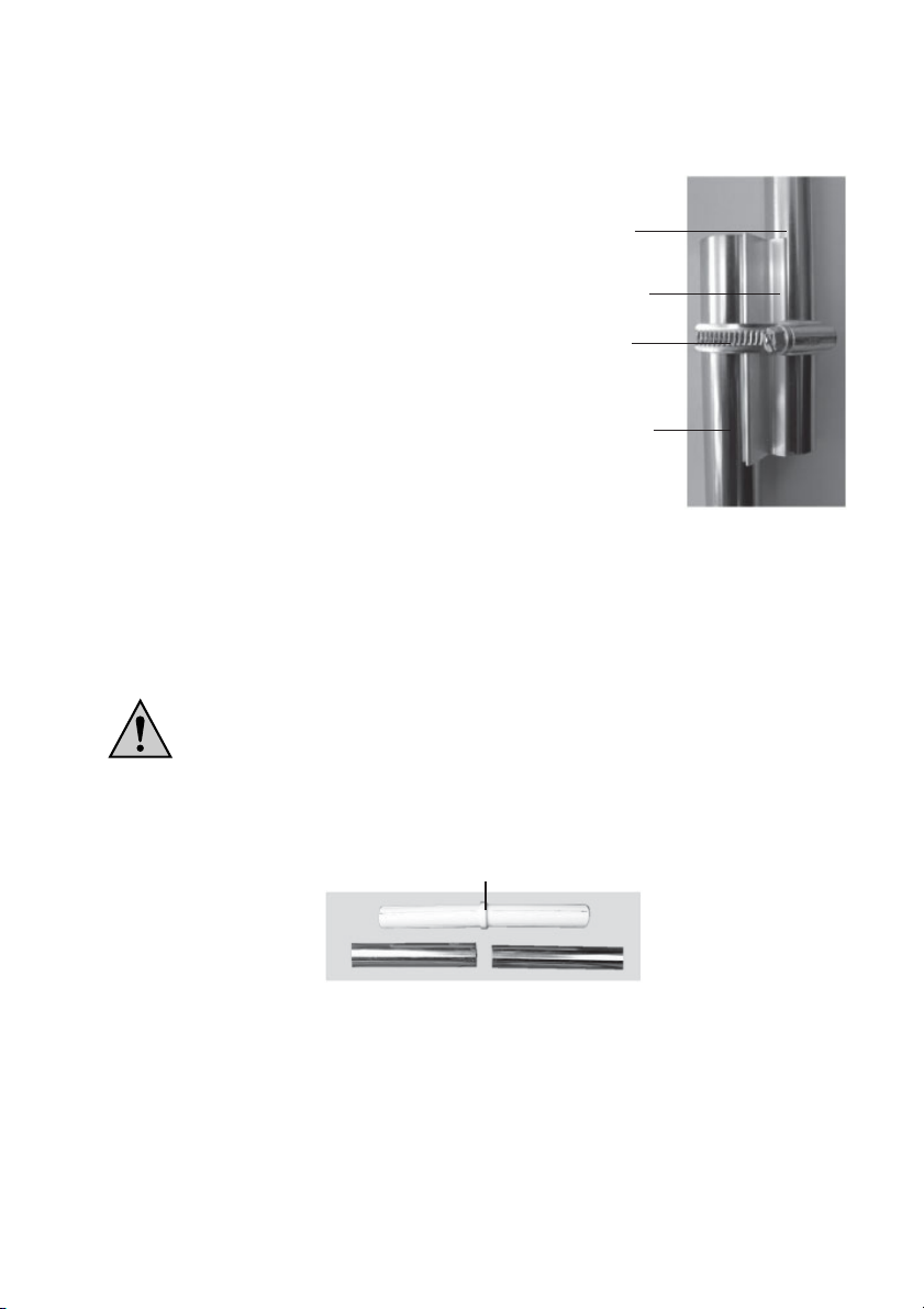
Proceed as follows for mounting:
1. Own individual installation mast
supplied
mounting rod
supplied shaped
aluminium part
mounting clip
installation mast
Fig. 2a
•Screw out the two small screws at the bottom
of the multipurpose sensor a little bit.
•Insert the supplied mounting rod of 25cm
from into the multipurpose sensor the bottom
in such a way that the two holes in the mounting
rod are directly positioned under the screws.
•Then tighten the two screws carefully (screws
are to be screwed into the holes of the
mounting rod).
•The mast required must have a diameter of
between 25mm and 45mm. It can either be a
free mast or a mounting angle, e.g. for a
satellite dish.
•Position the shaped aluminium part on one
side of this mast/mounting angle and put a
hose band clip over the two parts.
•Set the short mounting rod of the sensor against the other side of the shaped aluminium part
(on the right side in Figure 2 above) and tighten the hose band clip by using a screwdriver.
2. Optionally available installation mast (not included in the scope of delivery)
If you want to drive the rod with the flat tip (serves as an earth tip) into the ground by
means of a hammer, use a suited wooden clump in any case to protect the mast.
Otherwise, the upper end of the rod will be damaged (installation of the sensor mast
will not be possible any longer), guarantee will lapse!
•Assemble the single parts of the sensor mast. Plastic couplers combine the individual rods.
plastic coupler
Fig. 2b
•The flat rod end serves as an earth tip.
13
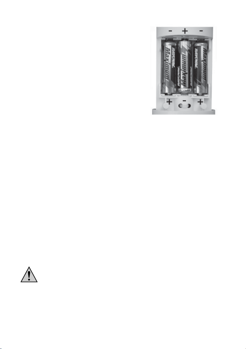
•After the installation of the mast, insert three batteries (AA/
Mignon) with the correct polarity into the battery compart-
ment. You will find the corresponding image in the battery
compartment (see also figure 3 on the right).
If possible use alkaline batteries.
As already described in chapter 6, accumulators
can be used, too. They, however, can have a
negative influence on the operating life, coverage
and operational safety.
•During the following 5 minutes, the sensor is in the so
called synchronisation mode in which it sends one data
package every 4 seconds.
During this period of time you should insert the batteries
into the base station so that it can identify the sensor.
Fig. 3
•Then close the housing of the multipurpose sensor again, slide the cover upwards and lock
it by turning it to the right (reverse direction than shown in Fig. 1).
•To avoid unnecessary long ways for checking the functions, the final positioning, e.g. in the
garden, should be performed only after a successfully completed functional test as described
at the beginning of this chapter.
The correct location of the multipurpose sensor is decisive for obtaining the most accurate
measuring values.
The temperature sensor inside the housing of the multipurpose sensor is positioned
at the top below the ”umbrellas” in a ventilated area of the housing. Therefore, in
direct sunlight only a slightly higher temperature value will be measured.
Please ensure that the wind sensor at the tip of the multipurpose sensor is not
positioned too close to houses, trees etc., because this could falsify the measured
values of the wind speed.
That’s why, the multipurpose sensor should be set up in a free space, e.g. in the
garden.
•The mast must firmly stick in the soil with the multipurpose sensor being positioned
approximately 2 m above the ground.
When selecting the place of installation, consider the safety for children, pets,
vehicles etc.
If the multipurpose sensor falls down, there is risk of injury or damage to
vehicles or other objects.
Make sure that there are no pipes (e.g. hose pipes for irrigating systems or
similar) at the place where the earth rod is inserted/driven into the ground.

14
b) Start-up of Other Sensors
If you want to use several additional temperature/air humidity sensors suited to the Weather
Station WS 200, insert the batteries into the sensor(s) now. A maximum number of 8 of such
sensors can be operated.
The installation, addressing and start-up of the sensor is to be performed according to their
operating instructions.
c) Start-up of the Base Station
The base station is designed to indicate all registered and calculated data on a clearly arranged
LC display. The sensors for indoor use (temperature, air humidity, air pressure) are also included
in the housing of the base station.
For this reason, ensure during the start-up or installation of the base station that a heating or
ventilation system (e.g. an air-conditioning system) is not in its proximity, because false data
could be indicated in such a case. Avoid direct sunlight, too!
Keep to the following order of steps during the start-up:
•Open the battery compartment on the back side of the base station (remove the foot first, if
necessary!).
•Insert four batteries (AA/Mignon) in the battery com-
partment paying attention to the correct polarity. You
will find the corresponding image in the battery
compartment (see also figure 4 on the right).
If possible use alkaline batteries.
As already described in chapter 6, accumu-
lators can be used, too. They, however, can
have a negative influence on the operating
life, coverage and operational safety.
•Close the battery compartment again.
•If the batteries are inserted, all segments of the LC
display will be shown briefly.
Fig. 4
•Afterwards, the base station activates the synchronisation mode for 15 minutes. In this period
of time all sensors received will be indicated one after the other.
If all your installed sensors have already been received, you can cause a premature
exit of the synchronisation mode by pressing any button, provided that all sensors
have already completed their own synchronisation mode.
If you face any problem in the identification of one sensor, you should wait as long
as the synchronisation time is finished. This process takes 15 minutes.

15
•After the synchronisation, the normal display of all weather data is shown.
Only sunrise and sunset as well as the phase of the moon have not been indicated
yet, because time and data are to be set before.
•Configure the base station as described in chapter 9 ”Configuration and Operation”.
•The base station can either be hung up on the wall (a suited opening is provided on the back
side) or placed on a foot onto a surface.
If you drive a nail into the wall or drill a hole for a plug with screw for this
purpose, pay attention that no power, gas or water pipes can be damaged,
grave danger!
•If you want to use the foot, first put the front central spike of the foot into the supports on the
back side of the base station. Then, swing the foot a little bit back till the two rear spikes lock
into the catch supports at the bottom of the base station.
d) Registration of Sensors during Normal Operation
When starting up the product, all available suited sensors are registered at the base station in
the synchronisation mode and then received during normal operation
(time required for the synchronisation of the base station takes about 15 minutes after inserting
the batteries, time required for the synchronisation of the sensors takes about 5 minutes after
inserting the batteries).
To register further new, additionally purchased sensors (or sensors lost during the battery
replacement) you do not need to follow the procedure of the initial start-up.
All data saved (minimum and maximum values, time etc.) would be lost during this
kind of proceeding.
Every day, the base station performs a synchronisation test at 8 a.m. and 6 p.m. so that it can
identify new sensors (or a sensor with battery replacement) automatically.
But if the new sensor is not indicated, the problem may be found in the coverage (see
chapter 12 ”Coverage”).
16
8. Indications of the LC Display
17 16
15 15
18
14
19
20
113
2
12
3
411
510
6 9
8
7
ABCD E

17
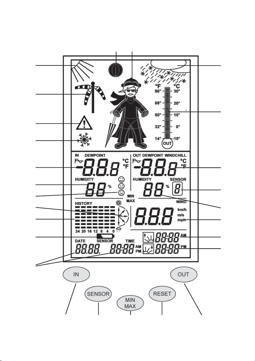
1indoor temperature
2indoor air humidity
3comfort zone indicator (for indicating comfortable/uncomfortable climate)
4indication of the air pressure tendency
5graphical presentation of the march (history), according to the unit selected
6indication of empty battery (”LoBat”)
7time and date indication
8sunset time
9sunrise time
10 current wind speed
11 current air-humidity value of the selected outdoor sensor
12 sensor number (no indication, if the multipurpose sensor has been selected)
13 current temperature value of the selected outdoor sensor
14 analogue temperature indication of the multipurpose sensor
15 symbols for the weather forecast (sunny, bright, cloudy, rainy)
16 animated ”Weather Willi” symbol
17 symbol for the phase of the moon
18 additional graphical representation (wind cone) for light, moderate and strong winds
19 bad weather warning
20 frost warning
Control key functions in normal operation (see chapter ”Configuration” for further functions):
AIN Switching the indoor temperature indication between temperature/dew
point
BSENSOR Selection of the outdoor sensor
CMIN/MAX Selection of the minimum or maximum value indication
DRESET No function
EOUT Switching the outdoor temperature indication between
temperature/dew point/windchill
Other symbols/terms:
Indicates that this value is presented in the march indication (5)
DEWPOINT Dew point
WIND CHILL Perceived temperature
MIN/MAX Minimum or maximum indication is active
18
9. Configuration and Operation
When the batteries have been inserted into the sensors and the batteries have been inserted
subsequently into the base station (this order is to be strictly followed), the data transmitted via
radio by the sensors should appear in the LC display of the base station.
a) Basic Settings, Configuration
The following settings are still required for operation:
•year, month, day, hour, minute
•latitude and longitude degrees of your location
•time zone
Only after these settings, the phase of the moon, MIN-/MAX-data and the sunrise/
sunset times as well as the date and time will be indicated.
Additional setting options:
•assignment of the march indication (air pressure, indoor or outdoor temperature; standard:
air pressure)
•unit of the temperature measurement (standard: °C)
•unit of the wind speed measurement (standard: km/h)
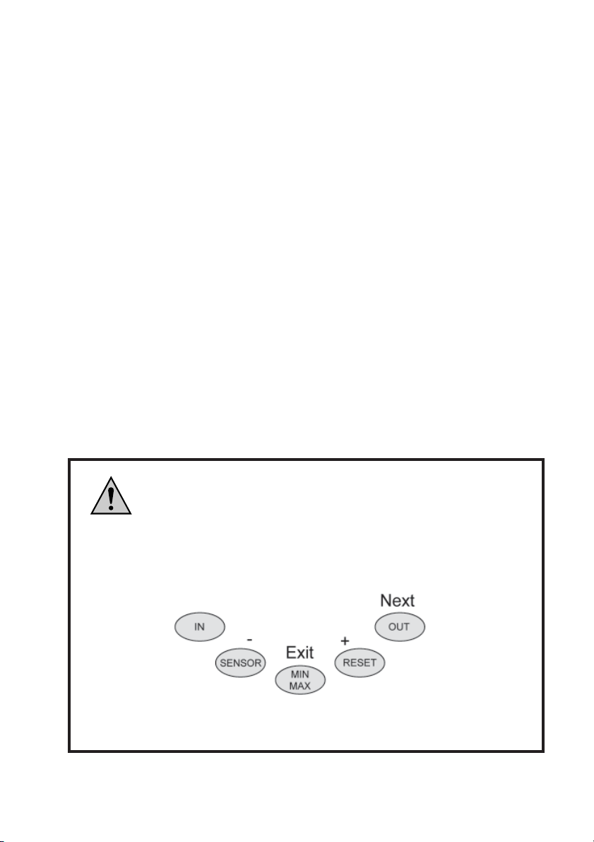
In the configuration mode the keys have the following functions:
Imprint Function Description
IN (not used, no function)
SENSOR - Decrease value
MIN/MAX EXIT Exit the configuration mode
RESET + Increase value
OUT NEXT Go to next setting
This key layout is also given on the back side of the weather station.
19
Please note:
If you press the +or -key during the individual settings a little bit longer, the values
will be changed rapidly.
After each setting procedure you can exit the configuration mode by pressing the
EXIT key or you can go the the next setting by activating the NEXT key.
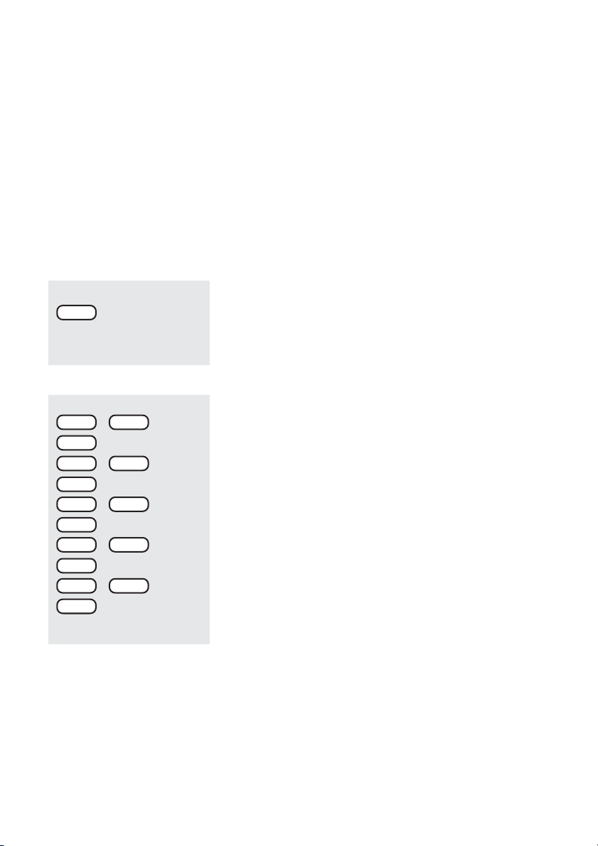
The configuration is performed according to the following order:
year month day minutes hours latitude degree (LA = latitude)
Längengrad (LO = “Longitude”) Zeitzone (ti) assignment of the march indication
temperature unit wind unit
Afterwards, the setting order restarts from the beginning.
IN >2 seconds
+-
+-
+-
NEXT
NEXT
NEXT
NEXT
+-
+-
NEXT
hours
minutes
day
month
year
Calling-up the configuration mode
Press the IN key for approx. 2 seconds till the display
changes.
The configuration mode can be closed at any time by
pressing the EXIT key (= MIN/MAX). See ”Exiting the
Configuration Mode”.
Setting the date and time
Set the current year via the +and -keys.
Press the NEXT key.
Set the month via the +and -keys.
Press the NEXT key.
Set the day via the +and -keys.
Press the NEXT key.
Set the minutes via the +and -keys.
Press the NEXT key.
Set the hours via the +and -keys.
Press the NEXT key, afterwards you can set the latitude
degree (in the display appears LA = latitude). See next page.

20
Entering the degrees of latitude/longitude
The entry of the location of the weather station is required
for the calculation of sunrise and sunset times.
The degree of latitude can be entered in the range from -
60.0°to +60.0°.
The degree of longitude can be entered in the range from
0.0°to 360.0°.
The position of Berlin is programmed by the manufac-
turer.
You can determine your location in different ways:
•You find a table with the coordinates of the most important
German towns in the chapter ”Position Table”. Select a
town close to you and enter its coordinates.
•If you possess a GPS navigation device, e.g. in your car
or a mobile one, you can take over its location information
and then you have your exact position.
•You can also get the exact coordinates via the Internet.
It provides numerous pages which contain information
on navigation.
Please consider the fact that the data for sunrise or sunset
are only exact at the sea or for a totally even landscape.
Hills, high forests etc. alter these values for your location.
Even for ideal positions the data may vary by some minutes,
because an approximation formula is used for the calculation.
Set the degree of latitude via the + and -keys.
For example: 52.5°, entry: 525
Press the NEXT key. Afterwards, the degree of longitude
can be entered. In the display these data are indicated by
LO (= longitude).
Set the degree of longitude via the +and -keys.
For example: 13.4°, entry: 0134
Press the NEXT key. Now, set the time zone. ”ti” is faded
into the display.
+-
NEXT
NEXT
+-
longitude
latitude
Table of contents
Other elv Weather Station manuals


Popular Weather Station manuals by other brands


Jung
Jung KNX 2225WSU-01 operating instructions

Gira
Gira 0334 Series operating instructions

Rain Bird
Rain Bird WS-PRO2 Installation, Operation, Maintenance, and Troubleshooting Manual

Vaillant
Vaillant VRC 470 instruction manual

Omega
Omega WMS831 user guide

Oregon Scientific
Oregon Scientific RGR126NX user manual


