Elvaco CMa10w User manual

CMa10w, CMa11w User's Manual– Version 1.3
CMa10w, CMa11w User's
Manual
CMa10w, CMa11w
The CMa10w/CMa11w is a Wireless M-Bus temperature
and humidity sensor for indoor use.
CMa10w/CMa11w complies with the OMS standard and
operates in Wireless M-Bus mode T1. CMa10w/CMa11w
is the perfect choice when wiring is not an option.

CMa10w, CMa11w User's M anual
Cm a10w ,Cm a11w
T1 Users M anual
English
page |
2
(
32
)
2013
-
06
-
12
Public
/
Published
Document id:
1090054
Version
1.
3
Contents
CONTENTS ............................................................................................................ 2
1DOCUM ENT NOTES .................................................................................... 4
1.1 COPYRIGHT AND TRADEM ARK ......................................................................................... 4
1.2 CONTACTS ..................................................................................................................... 4
2USING THIS M A NUA L ................................................................................. 5
2.1 PURPOSE AND AUDIENCE................................................................................................ 5
2.2 MODELS ........................................................................................................................ 5
2.3 ADDITIONAL AND UPDATED INFORM ATION....................................................................... 5
3INTRODUCTION........................................................................................... 6
3.1 PRODUCT CONFIGURATION ............................................................................................. 6
3.2 CAPABILITIES ................................................................................................................. 6
3.3 APPLICATIONS................................................................................................................ 6
4GETTING STA RTED ..................................................................................... 7
4.1 OVERVIEW ..................................................................................................................... 7
4.2 MOUNTING .................................................................................................................... 9
4.3 WIRELESS M-BUS.......................................................................................................... 9
4.3.1 Installation procedure ............................................................................................... 9
4.3.1.1 Installation procedure – Select Unencrypted m ode...................................... 9
4.3.1.2 Installation procedure – Select Encrypted mode........................................... 9
5A PPLICA TION DESCRIPTION .................................................................... 11
5.1 OPERATION .................................................................................................................. 11
5.1.1 Operation modes..................................................................................................... 11
5.1.1.1 Inactive mode...............................................................................................11
5.1.1.2 Installation procedure...................................................................................11
5.1.1.3 Norm al operation – Unencrypted mode ......................................................11
5.1.1.4 Norm al operation – Encrypted mode ...........................................................11
5.2 DISPLAY (CMA10W) .................................................................................................... 12
5.2.1 Display sym bols ...................................................................................................... 12
5.2.1.1 Operation mode indicator ............................................................................12
5.2.1.2 Battery level indicator ..................................................................................13
5.2.2 Display m enu ........................................................................................................... 14
5.2.2.1 Deactivate the product .................................................................................15
5.2.2.2 Reset to factory default ................................................................................15
5.2.2.3 Change language..........................................................................................15
5.2.2.4 Change contrast ...........................................................................................15
5.2.2.5 Enable/disable encryption ............................................................................15
5.2.2.6 Change transmit interval ..............................................................................15
5.2.2.7 Lock the product...........................................................................................15
5.3 LED INDICATIONS ........................................................................................................ 16
6A DM INISTRA TION OF THE PRODUCT ...................................................... 17
6.1 M-BUS PRODUCT IDENTIFICATION ................................................................................. 17
6.2 WIRELESS M-BUS M ODE.............................................................................................. 17

CMa10w, CMa11w User's M anual
Cm a10w ,Cm a11w
T1 Users M anual
English
page |
3
(
32
)
2013
-
06
-
12
Public
/
Published
Document id:
1090054
Version
1.
3
6.3 M-BUS ADDRESSING .................................................................................................... 17
6.4 OPERATION M ODE ........................................................................................................ 17
6.5 SPONTANEOUS TRANSMISSION .................................................................................... 17
6.6 M-BUS COM M ANDS ..................................................................................................... 17
6.6.1 Send spontaneous data (SND_NR)........................................................................ 17
6.6.1.1 Slave to master – Telegram 1 (SND_NR)......................................................17
7TROUBLESHOOTING ................................................................................. 23
7.1 COLLECTOR DOES NOT RECEIVE ANY TELEGRAM SENT FROM THE PRODUCT .................... 23
7.2 INFORM ATION NOT VISIBLE ON THE DISPLAY .................................................................. 23
7.3 TEMPERATURE VALUE IS INACCURATE........................................................................... 23
8TECHNICA L SPECIFICA TIONS .................................................................. 24
8.1 CHARACTERISTICS ........................................................................................................ 24
8.2 FACTORY DEFAULTS ..................................................................................................... 25
9TYPE A PPROVA LS .................................................................................... 26
10 SA FETY A ND ENVIRONM ENT................................................................... 27
10.1 SAFETY PRECAUTIONS.................................................................................................. 27
11 DOCUM ENT HISTORY ............................................................................... 28
11.1 DOCUMENT SOFTWARE AND HARDWARE APPLIANCE...................................................... 28
12 REFERENCES ............................................................................................. 29
12.1 REFERENCES ................................................................................................................ 29
12.2 TERM S AND ABBREVIATIONS......................................................................................... 29
12.2.1 Num ber representation........................................................................................... 29
13 A PPENDIX A – EX A M PLE ......................................................................... 30
13.1 DENOMINATION OF VALUES IN REPORTS........................................................................ 30
13.2 DENOMINATION OF VALUES FOR USE IN FILTERS ............................................................ 32

CMa10w, CMa11w User's M anual
Cm a10w ,Cm a11w
T1 Users M anual
English
page |
4
(
32
)
2013
-
06
-
12
Public
/
Published
Document id:
1090054
Version
1.
3
1Document notes
All inform ation in this manual, including product data, diagrams, charts, etc. represents
inform ation on products at the tim e of publication, and is subject to change w ithout prior
notice due to product improvements or other reasons. It is therefore recomm ended that
custom ers contact Elvaco AB for the latest product inform ation before purchasing a
CMa10w/CMa11w product.
The docum entation and product are provided on an “as is” basis only and m ay contain
deficiencies or inadequacies. Elvaco AB takes no responsibility for damages, liabilities or
other losses by using this product.
1.1 Co py r i g ht an d t r ad em ar k
© 2012, Elvaco AB. All rights reserved. No part of the contents of this m anual may be
transmitted or reproduced in any form by any m eans without the written perm ission of
Elvaco AB. Printed in Sweden.
CMa10w/CMa11w is a trademark of Elvaco AB, Sweden.
1.2 Co nt ac t s
Elvaco AB Headquarter
Teknikgatan 18
434 37 Kungsbacka
SWEDEN
Phone: +46 300 30250
Fax: +46 300 18440
E-M ail: info@elvaco.com
Elvaco AB Technical Support
Phone: +46 300 434300
E-M ail: support@elvaco.com
Online: http://www .elvaco.com

CMa10w, CMa11w User's M anual
Cm a10w ,Cm a11w
T1 Users M anual
English
page |
5
(
32
)
2013
-
06
-
12
Public
/
Published
Document id:
1090054
Version
1.
3
2Using this manual
2.1 Pu rp o se an d au d i en c e
This m anual covers inform ation needed to mount, configure and use the CMa10w/CMa11w
Wireless M-Bus indoor temperature and hum idity sensor. It is intended for field engineers
and developers.
2.2 M o del s
CMa10w, CMa11w
2.3 A ddi t ional and upd at ed i nf orm at i on
Latest docum entation version is available on Elvaco web site at http://www.elvaco.com.

CMa10w, CMa11w User's M anual
Cm a10w ,Cm a11w
T1 Users M anual
English
page |
6
(
32
)
2013
-
06
-
12
Public
/
Published
Document id:
1090054
Version
1.
3
3Introduction
3.1 Pr od u c t c o nf i g u r at i o n
Use the table below to find out the capabilities of your product.
Pr o d uc t
nam e
Co m m ent s
CMa10w Indoor Wireless M-Bus temperature and hum idity sensor w ith
display
CMa11w Indoor Wireless M-Bus temperature and hum idity sensor w ithout
display
Table 1 Product configuration
3.2 Capab ili t ies
The CM a10w/CMa11w is a 1-way Wireless M -Bus comm unicating temperature and
hum idity sensor for indoor use. CM a10w/CMa11w is the ideal product for com fort level
billing. The high accuracy sensor and user friendly handling m ake the CM a10w/CM a11w
the perfect choice for tenant owners.
3.3 A p pl i c at i ons
The CMa10w/CMa11w should be used in the following scenarios:
Indoor measurement of temperature and/or humidity
High accuracy indoor climate logging
Use instead of CMa10/CM a11 when w iring is not an option
CMa10w, CMa11w User's M anual
Cm a10w ,Cm a11w
T1 Users M anual
English
page |
7
(
32
)
2013
-
06
-
12
Public
/
Published
Document id:
1090054
Version
1.
3
4Getting Started
This chapter covers the steps required for getting the CM a10w/CMa11w installed and
operational. No pre-configuration is needed before using the CM a10w/CMa11w.
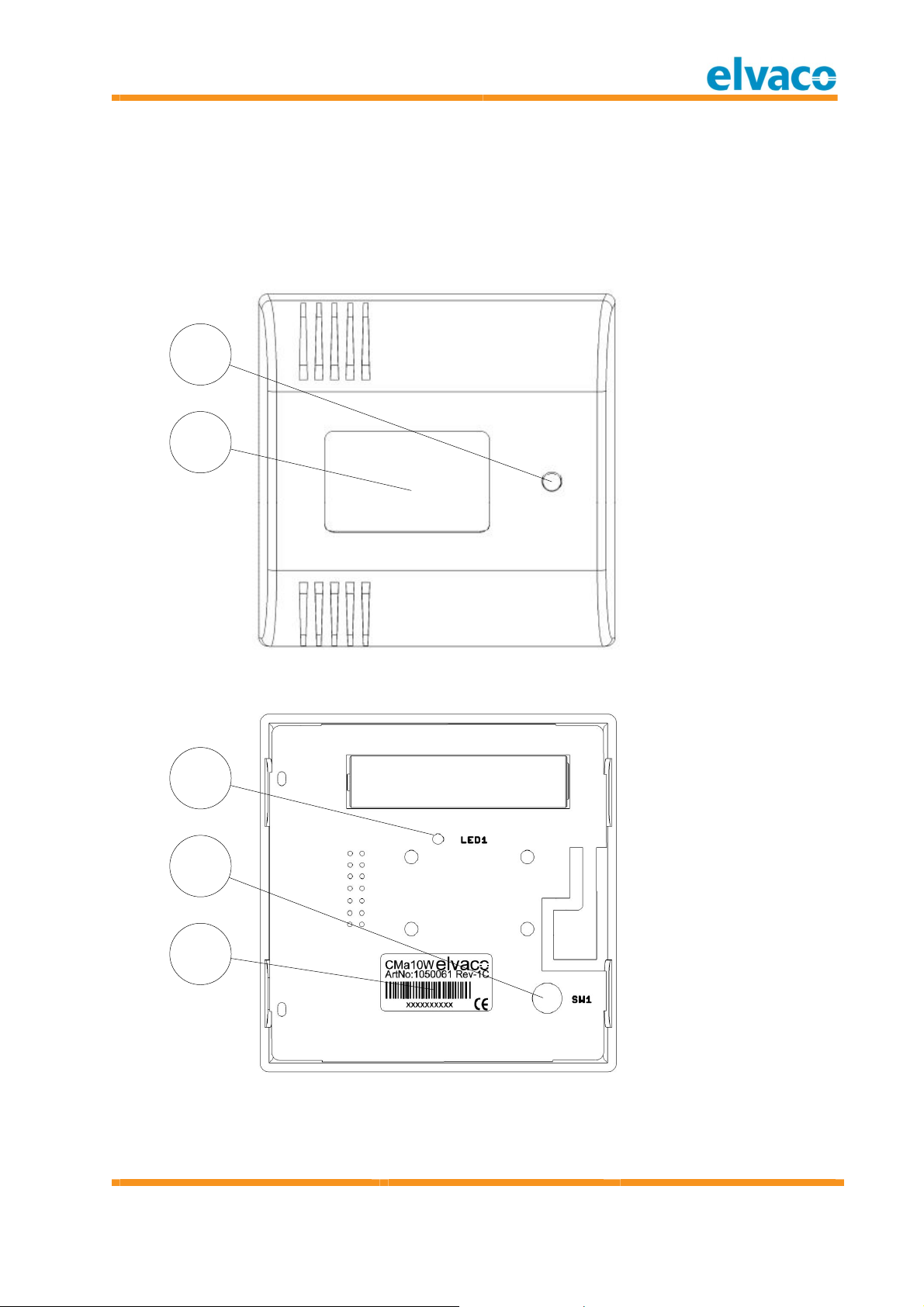
4.1 Ov erv i ew
1
2
Figure 1 Front view
3
4
5
Figure 2 Bottom view (rear cover rem oved)
1. Push-button (SW2)
(CMa10w)
2. Display (CM a10w)
3. LED1
4. Push-button (SW1)
5. Serial Number
(Identification)
CMa10w, CMa11w User's M anual
Cm a10w ,Cm a11w
T1 Users M anual
English
page |
8
(
32
)
2013
-
06
-
12
Public
/
Published
Document id:
1090054
Version
1.
3
6
DOWN
6
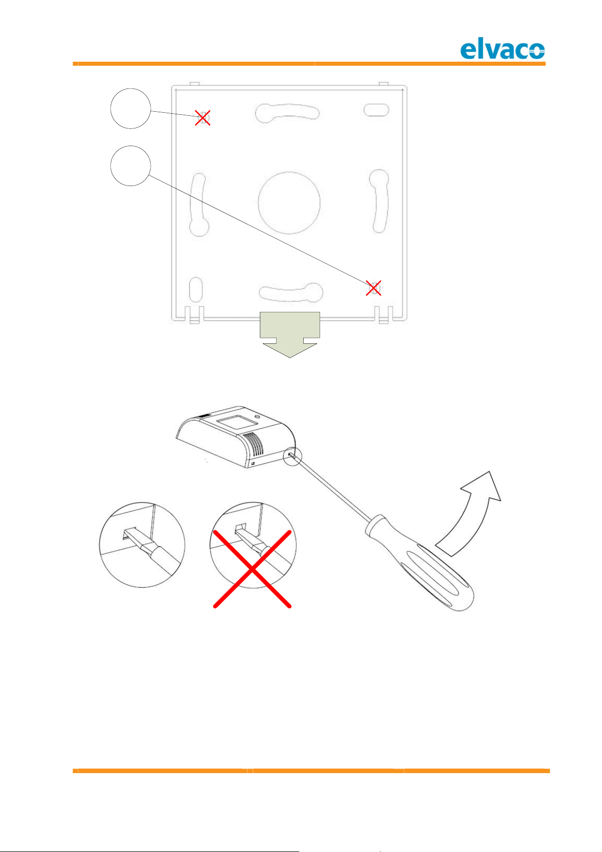
Figure 3 Rear cover
Figure 4 Dem ounting
6. Do not use for
mounting

CMa10w, CMa11w User's M anual
Cm a10w ,Cm a11w
T1 Users M anual
English
page |
9
(
32
)
2013
-
06
-
12
Public
/
Published
Document id:
1090054
Version
1.
3
4.2 M o un t i n g
When mounting the CM a10w/CMa11w, avoid rooms with a lot of supplem entary heat,
such as kitchens or south facing rooms. Position the sensor away from direct sunlight.
Avoid placing on an external wall or near an external door. M ake sure that the sensor is
not positioned closer than 1 m from the nearest radiator and at least 1.5 m above the floor.
The CMa10w/CMa11w can be mounted directly on the wall, or over a mounting box. If the
CMa10w/CMa11w is placed over a conduit pipe, it is recomm ended to fill the pipe to
prevent air flow which could affect accuracy of the values.
Remove the rear cover to be able to press the installation button SW1 (4).
IM PORTA NT
Please take the following in consideration:
Do not use mounting holes (6) as in Figure 3.
Turn the rear cover as shown in Figure 3.
Do not mount the product inside a steel cabinet, which will dram atically low er the
possibilities to connect to a collector.
4.3 Wi rel ess M -Bus
The product is delivered with the radio turned off. The radio must be manually switched on
during the installation procedure.
The pr o d uct w il l n ot be act ivat ed unt i l t he i nst allat ion pr oc ed ure is st art ed.
4.3 .1 In st allat i o n pro ced u re
The product can be installed and enabled in tw o modes:
U n en c ry pt ed m o de: Data is sent unencrypted and the encryption key is not
needed to decrypt the data.
En c ry pt ed m o de: Data is sent in encrypted m ode and the encryption key is
needed to decrypt the data.
Please advise your project m anager which operation mode is used in your project.
4.3 .1 .1 In st al lat i o n p r oc ed u re – Sel ec t U nen cr yp t ed m o d e
By perform ing the following steps, the product will start to send spontaneous
u n en c ry p t ed data:
1. Press and hold button SW1 (4) for 5 seconds, until LED1 (3) flashes fast. See Table 2 for
complete inform ation about LED indication.
2. Release SW1 (4)
The product will now start to send spontaneous unencrypted SND_NR telegrams every 6th
minute (default).
4.3 .1 .2 In st al lat i o n p r oc ed u re – Sel ec t En c r yp t ed m od e
By perform ing the following steps, the product w ill start to send spontaneous en cr y pt ed
data:
1. Press and hold button SW1 (4) for 10 seconds, until LED1 (1) flashes slow. See Table 2
for complete inform ation about LED indication.
2. Release SW1 (4)

CMa10w, CMa11w User's M anual
Cm a10w ,Cm a11w
T1 Users M anual
English
page |
10
(
32
)
2013
-
06
-
12
Public
/
Published
Document id:
1090054
Version
1.
3
3. The product will now start to send spontaneous encrypted SND_NR telegram s every 6th
minute (default).
IM PORTA NT
Please take the following in consideration:
After the product is activated, configuration can still be changed on the CM a10w
using the Setup menu, see section 5.2.
The device can be locked for future configuration, see section 5.2.2.7.

CMa10w, CMa11w User's M anual
Cm a10w ,Cm a11w
T1 Users M anual
English
page |
11
(
32
)
2013
-
06
-
12
Public
/
Published
Document id:
1090054
Version
1.
3
5Application description
This chapter covers general application description and configuration of the product.
5.1 Operat i o n
The product will automatically, after the installation procedure, send T1 messages every 6th
minute containing sensor data, such as instantaneous temperature and hum idity. The
product will also send product status inform ation, containing battery status and other
relevant inform ation.
Product configuration can be changed using the Setup menu (CM a10w) as long as the
product has not been locked for future configuration, see section 5.2.2.7.
5.1 .1 Op erat io n m o d es
The product has the following operation modes:
1. Inactive (on delivery)
2. Installation procedure (during installation)
3. Normal operation - encrypted m ode
4. Normal operation - unencrypted mode
5.1 .1 .1 In ac t iv e m o de
The product is delivered inactive, which means that the product does not perform any
tasks before an installation procedure is started. This saves the battery lifetim e and
ensures that there is no radio activity until the product is manually activated.
5.1 .1 .2 In st al lat i o n p r oc ed u re
The installation procedure is used to activate the product, see 4.3.1.
5.1 .1 .3 N o r m al op er at i o n – U n en c ry p t ed m o d e
In norm al operation unencrypted mode, the product will by default send spontaneous
u n en c ry p t ed m essages every 6th minute. This can be changed as long as the product has
not been locked. This mode is norm ally used w hen the collector or AM R/AMM system
does not handle AES encryption or if the AES key is unknown to the host system.
5.1 .1 .4 N o r m al op er at i o n – En c ry p t ed m o de
In norm al operation encrypted mode, the product will by default send spontaneous
en c r yp t ed messages every 6th m inute. This can be changed as long as the product has not
been locked. This mode is used to secure data sent from the product to the collector or
AM R/AM M system. To be able to decrypt the data, the private 128 bit AES key must be
know n by the collector or by the host system. The private 128 bit AES key is on demand
provided to the custom er by Elvaco AB.

CMa10w, CMa11w User's M anual
Cm a10w ,Cm a11w
T1 Users M anual
English
page |
12
(
32
)
2013
-
06
-
12
Public
/
Published
Document id:
1090054
Version
1.
3
5.2 D i spl ay (CM a1 0 w )
The display shows current sensor inform ation and is also used to change and view the
CMa10w configuration.
The display is in norm al operation turned off to save battery. The display is turned on as
soon as SW2 (1) is pushed and will be turned off if no button is pressed within 5 seconds.
When the display is turned off, the m enu page will be reset to the first page.
Please see Figure 5 for display design.
Figure 5 CMa10w display
5.2 .1 D isp lay sym bo ls
To easily show current operation and functionality of the product, the display is equipped
with display sym bols, w hich indicate Wireless M-Bus mode, encryption and battery level.
5.2 .1 .1 Op er at i o n m ode i n dicat or
This indicator shows if the product runs in encrypted or unencrypted mode. If the indicator
is visible, all comm unication is encrypted, otherwise all com munication is sent
unencrypted.
Sy m bo l D esc r i pt i on
Steady
Product is encrypting all messages with AES 128 bit encryption.
If the product is running in unencrypted mode, the operation mode
indicator is hidden.
CMa10w, CMa11w User's M anual
Cm a10w ,Cm a11w
T1 Users M anual
English
page |
13
(
32
)
2013
-
06
-
12
Public
/
Published
Document id:
1090054
Version
1.
3
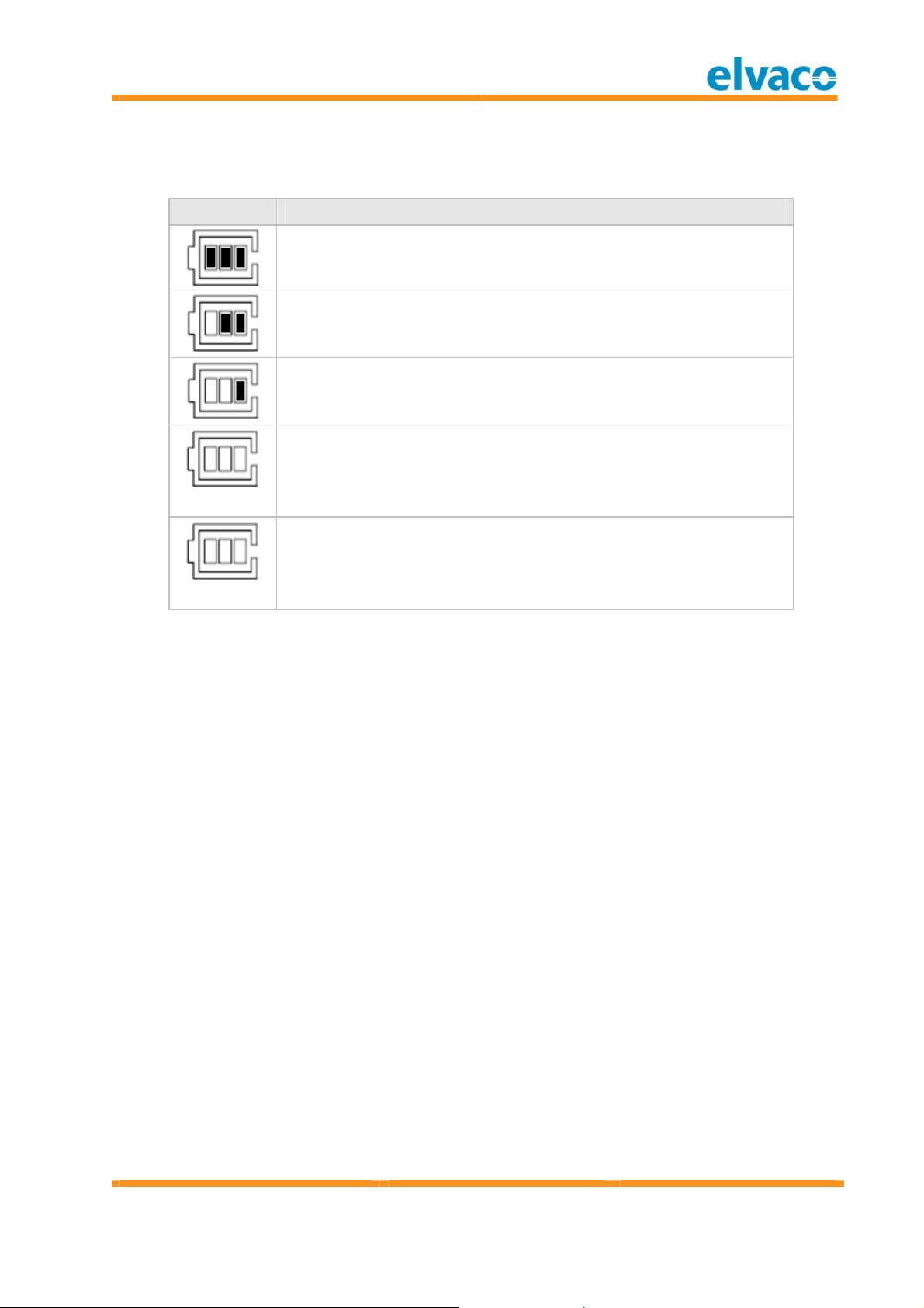
5.2 .1 .2 Bat t er y level indi cat or
The battery level indicator show s current battery level. The product should be exchanged
when the battery level indicator is flashing.
Sy m bo l D esc r i pt i on
Battery has full capacity.
Battery level is m edium .
Battery level is low.
Steady
Battery is almost em pty.
Flashing
Battery is em pty and the product will stop working within 12
months.
CMa10w, CMa11w User's M anual
Cm a10w ,Cm a11w
T1 Users M anual
English
page |
14
(
32
)
2013
-
06
-
12
Public
/
Published
Document id:
1090054
Version
1.
3
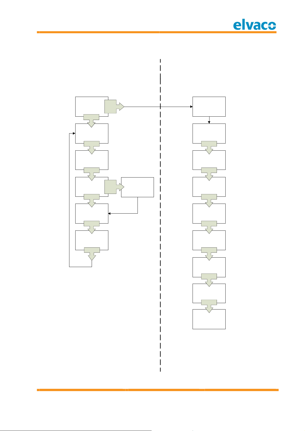
5.2 .2 D isp lay m enu
Please see Figure 6 for m enu options.
SETUP:
Setup Lock=n/Y
SETUP:
Language=Eng/
Deu/Sve
*END OF SETUP*
Restarting...
Temp: 25.5°C
Humi: 40% RH
24h AVERAGE
25.5°C
MIN MAX
25.5°C 25.5°C
40% RH 40% RH
1 h AVERAGE
25.5°C
Press 5 sec. To
reset MIN/MAX
value
SETUP:
Deactivate=n/Y
MIN/MAX values
are now reset
SW2
SW2
SW2
SW2
SW2
5s
SW2
SETUP:
Contrast= -10..+10
SETUP:
Encryption=n/Y
SETUP:
TxIntvl= 1..15 min
Standard menu
Enter next page by pressing SW2 Setup menu
Change valuesusing SW2
Confirm/enter next page by pressing SW1 for 1s.
SETUP:
Total Reset=n/Y
SW1
SW1
SW1
SW1
SW1
SW1
SW2
DISPLAY OFF
SW2
SW1
2s *SETUP STARTS*
SW1
Figure 6 CMa10w Display menu

CMa10w, CMa11w User's M anual
Cm a10w ,Cm a11w
T1 Users M anual
English
page |
15
(
32
)
2013
-
06
-
12
Public
/
Published
Document id:
1090054
Version
1.
3
5.2 .2 .1 D eac t ivat e t he pr oduct
Navigate to Setup m enu and select “y” in “Deactivate” m enu page. This will deactivate the
product and the product must be activated with a new installation procedure.
5.2 .2 .2 Reset t o f ac t ory def aul t
In order to reset the product configuration to factory default, navigate to “Total Reset” in
the setup m enu and select “y”.
5.2 .2 .3 Ch an g e l ang u ag e
Navigate to Setup m enu and select language (English, Deutsch or Svenska) in the
“Language” m enu page.
5.2 .2 .4 Ch an g e c o n t rast
Navigate to Setup m enu and select contrast from -10 to +10 in “Contrast” menu page. A
higher value indicates a higher contrast.
5.2 .2 .5 En ab le/d isab le en c r yp t i on
Navigate to Setup m enu and select “y” to enable encryption and “n” to disable encryption
in the “Encryption” menu page. This has the sam e functionality as activating the product
in encrypted or unencrypted mode.
5.2 .2 .6 Ch an g e t ran sm i t i nt erv al
Navigate to Setup menu and change interval from 1 minute to 15 minutes in the “TxIntvl”
menu page.
5.2 .2 .7 Lo c k t h e pr o d uc t
The product can be locked for future changes. Navigate to Setup menu and select “y” in
“Setup Lock” m enu page. This will disable the possibility to enter the Setup menu again.
IM PORTA NT
Lo ck in g t he p ro d uct c ann ot be u ndo ne and any conf i gu rat io n m ade cann ot be
c hanged. If y ou need t o unl o ck t he pr o duct , it n eeds t o b e sent t o Elvaco.

CMa10w, CMa11w User's M anual
Cm a10w ,Cm a11w
T1 Users M anual
English
page |
16
(
32
)
2013
-
06
-
12
Public
/
Published
Document id:
1090054
Version
1.
3
5.3 LED i ndi cat i ons
LED 1 St at e/D esc r ip t i on V i su al
Perm anently off Off
Fast flash
50 m s on / 50 ms off
Triggered w hen button is
pressed more than 5
seconds to select
unencrypted operation
mode. Releasing the button
in this state w ill select
unencrypted operation
mode.
Slow flash
250 ms on / 250 m s off
Triggered w hen button is
pressed more than 10
seconds to select encrypted
operation mode. Releasing
the button in this state will
select encrypted operation
mode.
Table 2 LED 1 indications

CMa10w, CMa11w User's M anual
Cm a10w ,Cm a11w
T1 Users M anual
English
page |
17
(
32
)
2013
-
06
-
12
Public
/
Published
Document id:
1090054
Version
1.
3
6Administration of the product
This chapter covers the configuration and Wireless M-Bus implementation of the product.
The Wireless M-Bus slave im plem entation is according to the new M -Bus standard
EN13757-2, EN13757-3, EN13757-4 and the OMS specification.
6.1 M -Bus pr oduc t i d ent i f ic at i on
The product can be identified by the following inform ation:
Manufacturer string = ELV
Medium = 0x1B (Room sensor)
Generation = 01-09 (CM a10w), 10-19 (CM a11w)
The generation field betw een product releases will o nly change (increase by 1) if the M-
Bus protocol inform ation changes between versions. Use the software version field in the
M-Bus telegram to identify current software version.
6.2 Wi rel ess M -Bus m ode
The product is using Wireless M -Bus mode T1, w hich m eans that the product sends
spontaneous data in one direction, from product to collector.
6.3 M -Bu s ad d ressi n g
The address used is a globally unique address, which is set during production.
6.4 Operat i o n m o d e
The product can operate in encrypted or unencrypted mode. In encrypted mode, OMS
encryption mode 5 is used with AES 128 bit key for all telegram s. When running in
unencrypted mode, all telegrams will be sent unencrypted
6.5 Spont aneous t ransm issi on
The product will automatically start sending spontaneous telegram s with m easurem ent
data after the installation procedure is completed. The product sends by default an
SND_NR telegram every 6th minute. The transmission interval is configurable in the Setup
menu of the CMa10w.
6.6 M -Bus c om m ands
All data in the tables are described unencrypted.
6.6 .1 Sen d spon t an eo us dat a (SND_NR)
During norm al operation, the Wireless M-Bus comm and SND_NR is sent by default every
6th minute.
6.6 .1 .1 Sl av e t o m ast er – Telegr am 1 (SND _N R)
By t e i n dex D at a D esc r i pt i on
0 0xnn L-Field
1 0x44 C-Field: SND_NR

CMa10w, CMa11w User's M anual
Cm a10w ,Cm a11w
T1 Users M anual
English
page |
18
(
32
)
2013
-
06
-
12
Public
/
Published
Document id:
1090054
Version
1.
3
2..3 0x9615 Manufacturer
“ELV”
4..7 0xnnnnnnnn Identification number
8 0xnn Version field
9 0x1B Device type (Medium) = Room sensor
10..11 0xnnnn CRC-field
12 0x7A CI-Field (Short header)
13 0xnn Access num ber
14 0xnn Status
15..16 0xnnnn Configuration w ord
17..18 0x2f2f AES check (idle filler)
19 0x02 Instantaneous temperature DIF
20 0x65 Instantaneous temperature VIF, external
temperature
21..22 0xnnnn Instantaneous temperature x 100
In case of error the temperature will be set
to 0.
23 0x42 | 0x72 1-hour temperature rolling average DIF,
storage number 1
0x42 = The value is available
0x72 = The value is not yet calculated
24 0x65 1-hour temperature rolling average VIF,
external temperature
25..26 0xnnnn 1-hour temperature rolling average x 100
This value is unavailable (0) until 1 hour has
passed since pow er-on. During this first
hour the value w ill be flagged as “value
during error state”, DIF bits 5 and 4 = 1.
This value is updated every 6 minute.
The temperature data will be 0 in case of
sensor error. See slave status byte in data
header.
27 0x82 | 0xb2 24-hour temperature rolling average DIF,
storage number 2
0x82 = The value is available
0xb2 = The value is not yet calculated
28 0x01 24-hour temperature rolling average DIFE
29 0x65 24-hour temperature rolling average VIF,
external temperature
30..31 0xnnnn 24-hour temperature rolling average x 100

CMa10w, CMa11w User's M anual
Cm a10w ,Cm a11w
T1 Users M anual
English
page |
19
(
32
)
2013
-
06
-
12
Public
/
Published
Document id:
1090054
Version
1.
3
This value is unavailable (0) until 24 hour
has passed since power-on. During this
period the value will be flagged as “value
during error state”, DIF bits 5 and 4 = 1.
This value is updated every hour.
The temperature data will be 0 in case of
sensor error. See slave status byte in data
header.
32 0x22 1-hour minim um tem perature DIF
33 0x65 1-hour minim um tem perature VIF, external
temperature
34..35 0xnnnn 1-hour minim um tem perature x 100
In case of error the temperature will be set
to 0.
This is the low est instantaneous
temperature since last 1-hour period.
36 0x12 1-hour m aximum temperature DIF
37 0x65 1-hour m aximum temperature VIF, external
temperature
38..39 0xnnnn 1-hour m aximum temperature x 100
In case of error the temperature will be set
to 0.
This is the highest instantaneous
temperature since last 1-hour period.
40 0x62 24-hour minimum temperature DIF
41 0x65 24-hour minimum temperature VIF, external
temperature
42..43 0xnnnn 24-hour minimum temperature x 100
In case of error the temperature will be set
to 0.
This is the low est instantaneous
temperature since last 24-hour period.
44 0x52 24-hour m aximum temperature DIF
45 0x65 24-hour m aximum temperature VIF,
external temperature
46..47 0xnnnn 24-hour m aximum temperature x 100
In case of error the temperature will be set
to 0.

CMa10w, CMa11w User's M anual
Cm a10w ,Cm a11w
T1 Users M anual
English
page |
20
(
32
)
2013
-
06
-
12
Public
/
Published
Document id:
1090054
Version
1.
3
This is the highest instantaneous
temperature since last 24-hour period.
48 0x02 Instantaneous relative hum idity DIF
49 0xfb Instantaneous relative humidity VIF,
extension table FB
50 0x1a Instantaneous relative hum idity VIFE
51..52 0xnnnn Instantaneous relative humidity x 10
In case of error the relative humidity will be
set to 0.
53 0x42 | 0x72 1-hour humidity rolling average DIF,
storage number 1
0x42 = The value is available
0x72 = The value is not yet calculated
54 0xfb 1-hour relative humidity VIF, extension
table FB
55 0x1a 1-hour relative humidity VIFE
56..57 0xnnnn 1-hour relative humidity x 10
In case of error the relative humidity will be
set to 0.
58 0x82 | 0xb2 24-hour humidity rolling average DIF,
storage number 2
0x82 = The value is available
0xb2 = The value is not yet calculated
59 0x01 24-hour humidity rolling average DIFE
60 0xfb 24-hour relative humidity VIF, extension
table FB
61 0x1a 24-hour relative hum idity VIFE
62..63 0xnnnn 24-hour relative humidity x 10
In case of error the relative humidity will be
set to 0.
64 0x22 1-hour minim um relative humidity DIF
65 0xfb 1-hour minim um relative humidity VIF,
extension table FB
66 0x1a 1-hour minim um relative humidity VIFE
67..68 0xnnnn 1-hour minim um relative humidity x 10
In case of error the relative humidity will be
set to 0.
This is the lowest instantaneous relative
hum idity since last 1-hour period.
Other manuals for CMa10w
3
This manual suits for next models
1
Table of contents
Other Elvaco Accessories manuals


