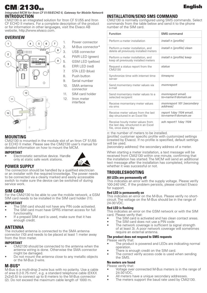
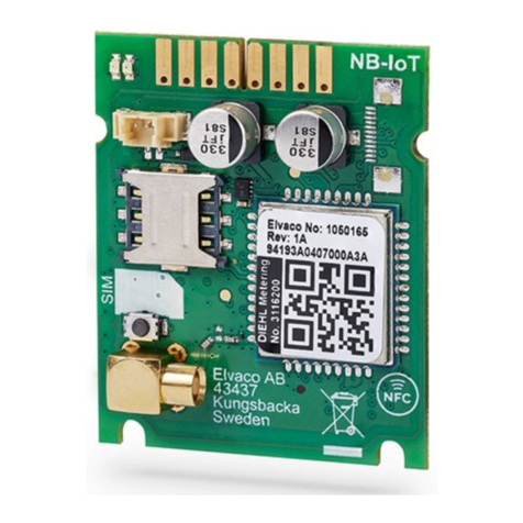
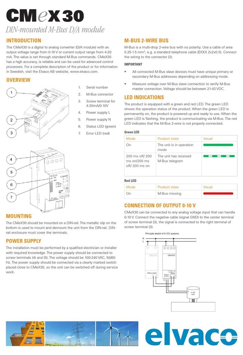
Elvaco CMi6110 User manual

CMi6110 User’s Manual English
CMi6110
User’s Manual
English
V1.3

CMi6110 User’s Manual English
CMi6110 User’s Manual English
page | 2 (42)
[2022-10]
v1.3
CONTENTS
1DOCUMENT NOTES .....................................................................................................4
1.1 COPYRIGHT AND TRADEMARK.........................................................................................4
1.2 CONTACTS..................................................................................................................... 4
2IMPORTANT USAGE AND SAFETY INFORMATION...................................................5
3USING THIS MANUAL ..................................................................................................6
3.1 PURPOSE AND AUDIENCE ............................................................................................... 6
3.2 ONLINE RESOURCES ...................................................................................................... 6
3.3 SYMBOLS.......................................................................................................................6
4INTRODUCTION............................................................................................................7
4.1 PURPOSE....................................................................................................................... 7
4.2 APPLICATION DESCRIPTION.............................................................................................7
4.3 PRODUCT FEATURES......................................................................................................7
4.4 COMPATIBILITY...............................................................................................................8
5GETTING STARTED......................................................................................................9
5.1 PURPOSE....................................................................................................................... 9
5.2 PRODUCT OVERVIEW CMI6110......................................................................................9
5.3 MOUNT AND START-UP THE DEVICE...............................................................................10
5.3.1 Mounting PSU power ................................................................................................ 10
5.3.2Mounting battery power............................................................................................. 10
5.3.3 Antenna connection................................................................................................... 10
5.3.4 Start-up and LED indications..................................................................................... 11
5.3.5 Switch off/reboot module........................................................................................... 12
6INTEGRATION GUIDE ................................................................................................13
6.1 PURPOSE..................................................................................................................... 13
6.2 INTRODUCTION............................................................................................................. 13
6.3 STATUS AND CONFIGURATION PARAMETERS.................................................................. 13
6.3.1 L+G UH50 error codes.............................................................................................. 20
6.4 CHANGING APN VIA THE DM SYSTEM...........................................................................20
7ADMINISTRATION REFERENCE................................................................................21
7.1PURPOSE..................................................................................................................... 21
7.2 SECURITY AND ACCESS CONTROL................................................................................. 21
7.3 SCHEDULING READOUTS /TRANSMISSIONS ...................................................................21
7.3.1 Time handling............................................................................................................ 21
7.3.2 Synchronization......................................................................................................... 21
7.3.3 Randomized transmissions....................................................................................... 21
7.3.4 Data retransmission .................................................................................................. 22
Example 1............................................................................................................................... 22
Example 2............................................................................................................................... 23
7.4 METER DATA TRANSMISSION.........................................................................................23
7.4.1 Message formats....................................................................................................... 23
7.4.2 Message encoding.................................................................................................... 24
7.5 CONFIGURATION OPTIONS ............................................................................................32
8TECHNICAL SPECIFICATIONS..................................................................................38
9TYPE APPROVALS.....................................................................................................40

CMi6110 User’s Manual English
CMi6110 User’s Manual English
page | 3 (42)
[2022-10]
v1.3
10 DOCUMENT HISTORY................................................................................................41
10.1 VERSIONS.................................................................................................................... 41
11 REFERENCES.............................................................................................................42
11.1 TERMS AND ABBREVIATIONS .........................................................................................42
11.2 NUMBER REPRESENTATION ..........................................................................................42

CMi6110 User’s Manual English
CMi6110 User’s Manual English
page | 4 (42)
[2022-10]
v1.3
1 Document notes
All information in this manual, including product data, diagrams, charts, etc. represents information on
products at the time of publication, and is subject to change without prior notice due to product
improvements or other reasons. It is recommended that customers contact Elvaco AB for the latest
product information before purchasing a CMi Series product.
The documentation and product are provided on an “as is” basis only and may contain deficiencies or
inadequacies. Elvaco AB takes no responsibility for damages, liabilities or other losses by using this
product.
1.1 Copyright and trademark
© 2022 Elvaco AB. All rights reserved. No part of the contents of this manual may be transmitted or
reproduced in any form by any means without the written permission of Elvaco AB. Printed in Sweden.
CMi Series is a trademark of Elvaco AB, Sweden.
1.2 Contacts
Elvaco AB
Kabelgatan 2T
434 37 Kungsbacka
SWEDEN
Phone: +46 300 30250
E-Mail: [email protected]om
Elvaco AB Technical Support
Phone: +46 300 434300
E-Mail: support@elvaco.se
Online: http://www.elvaco.com

CMi6110 User’s Manual English
CMi6110 User’s Manual English
page | 5 (42)
[2022-10]
v1.3
2 Important usage and safety information
The following safety precautions must be observed during all phases of the operation, usage, service or
repair of any CMi Series product. Users of the product are advised to convey the information to users and
operating personnel and to incorporate these guidelines into all manuals supplied with the product.
Failure to comply with these precautions violates safety standards of design, manufacture and intended
use of the product. Elvaco AB assumes no liability for customer’s failure to comply with these
precautions.
CMi6110 receives and transmits radio frequency energy while switched on. Remember that interference
can occur if the product is used close to TV sets, radios, computers or inadequately shielded equipment.
Follow any special regulations and always switch off the product wherever forbidden, or when you
suspect that it may cause interference or danger.
The device or antenna of the product must not be mounted closer than 0.5 m from areas where people
are staying permanently in order not to risk exposing people to RF fields.
To use the product's NFC TAG, follow the instructions issued by the manufacturer of the NFC reader for
safe and efficient operation.
Ensure yourself that power supply and/or battery-unit connected to CMi6110 fulfil EN 62368-1 or
equivalent safety standard.
For guaranteed lifetime of a battery-operated device, configuration and settings must be approved by
Elvaco and not changed during the lifetime of the device.

CMi6110 User’s Manual English
CMi6110 User’s Manual English
page | 6 (42)
[2022-10]
v1.3
3 Using this manual
3.1 Purpose and audience
This manual provides all information needed to mount, connect, configure and integrate a CMi6110 NB-
IoT module and targets system integrators.
This manual will provide device-specific information for CMi6110, such as status/configuration
parameters and message formats, needed to integrate the module with a DM system and a receiving MD
server.
It is meant to be used along with the common “Elvaco NB-IoT Module Integrators Manual”, which
provides information about the bootstrapping process, device management, data transport and
encryption.
3.2 Online resources
To download the latest version of this user’s manual, or to find information in other languages, please
visit https://www.elvaco.com/.
3.3 Symbols
The following symbols are used throughout the manual to emphasize important information and useful
tips:
The Note symbol is used to mark information that is important to take into consideration for
safety reasons or to assure correct operation of the meter connectivity module.
The Tip symbol is used to mark information intended to help you get the most out of your
product. It can for example be used to highlight a possible customization option related to the
current section.
The following symbols are used to provide information on how the product should be used:
Symbol
Description
Waste electrical products should not be disposed of with household waste. Please recycle
where facilities exist. Contact your Local Authority for recycling advise.
Electrostatic-sensitive device. Please observe the necessary ESD protective measures when
installing the MCM.

CMi6110 User’s Manual English
CMi6110 User’s Manual English
page | 7 (42)
[2022-10]
v1.3
4 Introduction
4.1 Purpose
This chapter provides a general description of CMi6110. In the next-coming sections you will learn more
about possible applications for the product and how it can be combined with other products to build
versatile solutions.
4.2 Application description
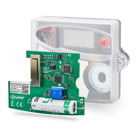
CMi6110 is a cost-effective NB-IoT meter connectivity module, which is mounted inside a Landis+Gyr
UH50 heat meter or UC50 calculator. As soon as the device has been mounted and deployed, it will start
to deliver meter data to a receiving system via the NB-IoT (LPWAN) network. The product is ideal for
applications where long range and high energy-efficiency are required and a lower bandwidth is not a
concern.
4.3 Product features
Key features of CMi6110 include:
•IoT-ready
As soon as the meter connectivity module has been mounted and started up, it will automatically
initiate transmission of meter data without any manual steps needed. The CMi6110 is prepared
for seamless integration with all leading IoT platforms. It utilizes standards such as LWM2M,
MQTT-SN and SenML-CBOR for fast and easy integration.
•Battery or mains supply operated
CMi6110 has several options for power supply. It can be battery operated for up to 10 years with
daily transmission of meter data.
•One-Touch Commissioning
The product uses the Elvaco One-Touch Commissioning (OTC) to configure and deploy products
quickly and securely. Using the Elvaco OTC App, simply enter your desired settings and place
your mobile phone on the right side of the UH50 meter/UC50 calculator. New settings will be
applied instantaneously via NFC.
•Flexible message scheme
CMi6110 has different message formats to choose from, which makes it easy to setup the device
for your specific project.

CMi6110 User’s Manual English
CMi6110 User’s Manual English
page | 8 (42)
[2022-10]
v1.3
4.4 Compatibility
CMi6110 is compatible with any L+G UH50 meter using software version 5.15 or later and L+G UC50
calculators using software version 8.06 or higher.
CMi6110 can be supplied by using one of the following PSUs: Elvaco’s 230V CMip2110 or Landis+Gyr:
WZU-110/AC230-xx, WZU-ACDC24-50 or battery WZU-NB-IoT-BAT.

CMi6110 User’s Manual English
CMi6110 User’s Manual English
page | 9 (42)
[2022-10]
v1.3
5 Getting started
5.1 Purpose
This chapter provides instructions on how to get started with the CMi6110. After reading and carefully
following each step of this chapter, the MCM will be mounted and deployed.
Product specification CMi6110
5.2 Product overview CMi6110
Figure 1: CMi6110 frontside
1. Meter Interface
2. PSU Power Connector
3. Battery Power Connector
4. Push Button
5. Antenna Connector (MCX female)
6. NFC Antenna
7. SIM card holder
8. Green LED
9. Red LED
Figure 2: CMi6110 backside

CMi6110 User’s Manual English
CMi6110 User’s Manual English
page | 10 (42)
[2022-10]
v1.3
5.3 Mount and start-up the device
In order to use CMi6110, a SIM card (size: Nano) needs to be mounted in the SIM card holder (7), see
Figure 3. The module is thereafter mounted in module slot 2 of a L+G UH50 heat meter or a L+G UC50
heat calculator with software version 5.15/8.06 or higher. Grab the module by the outer edges and gently
press it into position.
Figure 3: SIM card mounting
5.3.1 Mounting PSU power
Make sure to connect the (longer) 2-wire cord from the power supply unit (24V or 110/230V) in the right
compartment, see
Figure 4, to the power connector (2). For more information about PSU, please see manual for CMip2110/
WZU-AC230-xx.
5.3.2 Mounting battery power
Remove the red flap inside the meter. If the right compartment for power supplies is equipped, remove
that battery or power supply unit. For the meter supply, a Landis+Gyr WZU-BC+GUM battery has to be
inserted into the left compartment, as illustrated in
Figure 4. Mount the Landis+Gyr WZU-NB-IoT-BAT (battery+holder) in the right compartment. Battery
operation is available from FW 1.03. Models with earlier FW can be remotely updated.
•The battery supplying the meter must be connected before connecting the battery supplying the
CMi6110.
•Removing the meter’s red flap is only allowed for this purpose!
•The battery holder (made of isolating material) substitutes the function of the red flap. Once
inserted into the meter it cannot be removed.
5.3.3 Antenna connection
Make sure to connect an external antenna (released by the supplier) with MCX connector to the module
in the UH50/UC50.
Figure 4 below illustrates how the antenna cable should be routed. Push the connector gently into the
socket on the module.
•The antenna should be mounted at least 0.5 meter away from the meter to avoid interference.
•The rubber gromets may not be cut.
•Punch a small hole with 3mm diameter through the gromet.A 3mm hex key (Allen key), for
example, is a suitable tool.
•Make sure to remove the strain relief (metallic clip) and do not remount it due to the risk of
damaging the antenna cable. If you want to add additional strain relief, mount a cable tie on the
antenna cable, close to the cable entry inside the enclosure.

CMi6110 User’s Manual English
CMi6110 User’s Manual English
page | 11 (42)
[2022-10]
v1.3
Figure 4: Mounting instructions
Note that the battery supplying the
meter must be connected before the
battery supplying the NB-IoT module
is connected to the CMi6110.
5.3.4 Start-up and LED indications
Module activation
Upon delivery, CMi6110 will be set to passive mode, which means that no messages will be transmitted
from the module. Please make sure a SIM card (size: Nano) has been mounted before activating the
module. There are two ways to activate the module:
1. Press down the push button for at least 5 seconds until the green LED lights up, then release the
button. CMi6110 will confirm start-up by flashing its red and green LEDs for one second. At the
order process a configuration can be added and the product will utilize the settings of this
configuration when activated.
2. Via the Elvaco mobile application. Go to Apply mode, set the power mode to “active” and press
Apply settings.Place the phone on the right side of the meter. The mobile phone should vibrate
three times. This indicates that settings have successfully been applied.
Network Connection
When activated, CMi6110 will attempt to connect to the mobile network. The phase is indicated by the
green and red LED lights up for 1 second, followed by short flashes on the green LED until the module
has joined the mobile network. When CMi6110 succeeds in connecting to the mobile network, the green
LED will lighten up for 8 seconds, as illustrated by Figure 5. A meter readout will automatically be sent to
the receiving system.
If the module fails to join the mobile network, it will perform retries until it succeeds. The time between
each attempt will increase for every attempt until it is performed once every day. A new join attempt cycle
can be manually started anytime by using the push button to reboot the module or by deactivating and
activating the module using the Elvaco OTC App.
Figure 5: LED indications, network connection

CMi6110 User’s Manual English
CMi6110 User’s Manual English
page | 12 (42)
[2022-10]
v1.3
5.3.5 Switch off/reboot module
To reboot the module, press and hold the push button for 5-15 seconds. Release the button when the
green LED is lit.
To switch off the module, press and hold the push button for 15-20 seconds. Release the button when
the red LED is lit.
Figure 6: LED indication, reboot / switch-off

CMi6110 User’s Manual English
CMi6110 User’s Manual English
page | 13 (42)
[2022-10]
v1.3
6 Integration guide
6.1 Purpose
This chapter provides the technical details needed to integrate an Elvaco NB-IoT module with a MD
and/or DM server.
Note that this section will provide device-specific information and is meant to be used with the
common “Elvaco NB-IoT MCM Integrator’s guide”.
6.2 Introduction
For device management, the module will act as a LWM2M client connecting to a LwM2M server. The
Device Management system enables configuration and monitoring of a CMi6110 module remotely. This
includes setting configuration parameters, update the firmware and trigger momentaneous/historical
readouts of the module.
Upon activation, the device will attempt to connect to its configured bootstrap server via the mobile (NB-
IoT) network. When successful, the module will receive connection credentials, i.e. IP addresses to the
DM server and the meter data server.
The module will thereafter connect to the DM server and perform a DTLS handshake to generate the
session key used to encrypt the data that is transmitted between DM server and module. Note that using
DTLS is optional, and the product also support unencrypted communication.
The module will thereafter connect to the MQTT-SN gateway and perform a DTLS handshake to
generate the sessions keys used to encrypt the session key used to encrypt the meter data transport.
Each module has a security chip where a device-unique set of keys are stored. These are provisioned to
the module during production. The UDP transport of both DM and MDM can be secured using DTLS 1.2.
Either the pre-provisioned keys can be used, or new keys can be provisioned during the bootstrap phase.
6.3 Status and configuration parameters
Table 1 below provides a list of all standard LwM2M status and configuration parameters available for
CMi6110. Elvaco product specific LwM2M objects are listed in Table 2.
Standard LwM2M status and configuration parameters:
Op.
LwM2M object
LwM2M resource
ID
Type
Range or
Enumeration
Comment
R
LwM2M Security
LWM2M Server
URI
0/0/0
String
Bootstrap URI
R
LwM2M Security
Bootstrap server
0/0/1
Bool
TRUE
R
LwM2M Security
Security Mode
0/0/2
Integer
0..4
BS Security
mode
0 = PSK mode
3 = No security
R
LwM2M Security
PSK Identity
0/0/3
Opaque
DevEUI
-
LwM2M Security
Secret Key
0/0/4
Opaque
Bootstrap PSK
R
LwM2M Security
Short Server ID
0/0/10
Integer
1..65534
R
LwM2M Server
Short Server ID
1/0/0
Integer
1..65534
R
LwM2M Server
Lifetime
1/0/1
Integer
E
LwM2M Server
Bootstrap-
Request Trigger
1/0/9
R(W)
LwM2M Security
LWM2M Server
URI
0/1/0
String
DM ServerURI
Writable by
Bootstrap server
R
LwM2M Security
Bootstrap server
0/1/1
Bool
FALSE

CMi6110 User’s Manual English
CMi6110 User’s Manual English
page | 14 (42)
[2022-10]
v1.3
Op.
LwM2M object
LwM2M resource
ID
Type
Range or
Enumeration
Comment
R(W)
LwM2M Security
Security Mode
0/1/2
Int
0..4
DM Security
mode
Writable by
Bootstrap server
R
LwM2M Security
PSK Identity
0/1/3
Opaque
DM PSK identity
(DevEUI)
(W)
LwM2M Security
Secret Key
0/1/4
Opaque
DM PSK
Writable by
Bootstrap server
R
LwM2M Security
Short Server ID
0/1/10
Integer
1..65534
R
LwM2M Server
Short Server ID
1/1/0
Integer
1..65534
R
LwM2M Server
Lifetime
1/1/1
Integer
DM lifetime
E
LwM2M Server
Registration
Update Trigger
1/1/8
R
Device
Manufacturer
3/0/0
String
Manufacturer
("Elvaco")
R
Device
Model Number
3/0/1
String
Product model
("CMi6110")
R
Device
Serial Number
3/0/2
String
DevEUI
R
Device
Firmware Version
3/0/3
String
Firmware
version
E
Device
Reboot
3/0/4
Reboot
R
Device
Available Power
Sources
3/0/6/0
Integer
0..7
Power source
1: Internal
battery
2: External
battery
6: AC (Mains)
power
R
Device
Power Source
Voltage
3/0/7/0
Integer
Power source
voltage
(Millivolt)
R
Device
Battery level
3/0/9
0..100
Battery level (in
%)
R
Device
Error Code
3/0/11/0
0..8
Error codes,
according to
LwM2M 1
RW
Device
Current Time
3/0/13
Time
Current time
RW
Device
UTC Offset
3/0/14
String
UTC Offset
UTC+X (ISO
8601)
R
Device
Hardware version
3/0/18
String
Hardware
version
R
Connectivity
Monitoring
Network Bearer
4/0/0
Integer
0..50
7 = NB-IoT
R
Connectivity
Monitoring
Available Network
Bearer
4/0/1/0
Integer
0..50
7 = NB-IoT
R
Connectivity
Monitoring
Radio Signal
Strength
4/0/2
Integer
RSRP
(NRSRP)
R
Connectivity
Monitoring
APN
4/0/7/0
String
APN
R
Connectivity
Monitoring
Cell ID
4/0/8
Integer
Cell ID
R
Connectivity
Monitoring
SMNC
4/0/9
Integer
0..999
MNC
PLMN = SMNC
+ SMCC

CMi6110 User’s Manual English
CMi6110 User’s Manual English
page | 15 (42)
[2022-10]
v1.3
Op.
LwM2M object
LwM2M resource
ID
Type
Range or
Enumeration
Comment
R
Connectivity
Monitoring
SMCC
4/0/10
Integer
0..999
MCC
PLMN = SMNC
+ SMCC
W
Firmware
Update
Package URI
5/0/1
Firmware
Update URI
E
Firmware
Update
Update
5/0/2
Firmware
Update Trigger
R
Firmware
Update
State
5/0/3
Integer
0..3
Firmware
Update Status
0: Idle
1: Downloading
2: Downloaded
3: Updating
R
Firmware
Update
Update result
5/0/5
Integer
Firmware
Update Result
R
Firmware
Update
Firmware Update
Protocol Support
5/0/8/0
Integer
0..5
0 = CoAP
R
Firmware
Update
Firmware Update
Delivery Method
5/0/9
Integer
0..2
0 = Pull only
’R
LwM2M Cellular
Connectivity
PSM Timer
10/0/4
Integer
NB-IoT T3412.
.
R
LwM2M Cellular
Connectivity
Active Timer
10/0/5
Integer
NB-IoT T3324.
R
LwM2M Cellular
Connectivity
eDRX parameters
for NB-S1 mode
10/0/9
Opaque
8 bit
NB-IoT eDRX.
R
LwM2M Cellular
Connectivity
Activated Profile
names
10/0/11
ObjLink
Link to APN
Connection
Profile object
RW
LwM2M APN
Connection
Profile
Profile name
11/[0,1]/0
String
RW
LwM2M APN
Connection
Profile
APN
11/[0,1]/1
String
Manual APN
Writable in
object resource
1.
RW
LwM2M APN
Connection
Profile
Auto select APN
by device
11/[0,1]/2
Boolean
Auto APN Mode
Writable in
object resource
1.
RW
LwM2M APN
Connection
Profile
Authentication
Type
11/[0,1]/4
Integer
0..3
3 = None,
Writing currently
not supported
Table 1: Standard LwM2M objects
Elvaco product specific LwM2M objects:
Op.
LwM2M object
LwM2M resource
ID
Type
Range or
Enumeration
Comment
RW
Elvaco MCM
Config
Meter Readout
Interval
33906/./0
Integer
Interval in
minutes
RW
Elvaco MCM
Config
Report data
encoding
33906/./1
Integer
0 =
SenML/CBOR
1 = JSON
2 = MBus

CMi6110 User’s Manual English
CMi6110 User’s Manual English
page | 16 (42)
[2022-10]
v1.3
Op.
LwM2M object
LwM2M resource
ID
Type
Range or
Enumeration
Comment
RW
Elvaco MCM
Config
Report frame type
33906/./2
Integer
42 =
CMi6110_Stand
ard 43 =
CMi6110_Exten
ded
RW
Elvaco MCM
Config
Eco mode
enabled
33906/./3
Boolean
RW
Elvaco MCM
Config
NFC Enabled
33906/./4
Boolean
R
Elvaco MCM
Config
NFC Config-
locked
33906/./5
Boolean
W
Elvaco MCM
Config
Adjust time
33906/./6
Integer
Adjustment in
seconds
E
Elvaco MCM
Config
Instantaneous
readout trigger
33906/./1
0
Trigger a meter
readout.
E
Elvaco MCM
Config
Historic resend
trigger
33906/./1
3
Trigger upload
of all historic
data
R
Elvaco MCM
Config
Historic resend
status
33906/./1
4
Integer
Number of
messages in
uplink queue
E
Elvaco MCM
Config
Apply APN
staging profile
33906/./1
5
Apply APN
staging profile.
R
Elvaco MCM
Config
Config write status
33906/./1
6
Boolean
Result of last
config write to
flash
RW
Elvaco MCM
Config
Meter Report
Interval
33906/./1
7
Integer
Interval in
minutes
RW
Elvaco MCM
Config
Meter Transmit
Interval
33906/./1
8
Integer
Interval in
minutes
RW
Elvaco MCM
Config
Meter Transmit
Offset
33906/./1
9
Integer
Offset in
minutes
RW
Elvaco MCM
Config
Meter Transmit
Delay
33906/./2
0
Integer
Delay in minutes
RW
Elvaco MCM
Config
Meter Uploads
Per Tx
33906/./2
1
Integer
Max number of
messages per tx
interval
RW
Elvaco MCM
Config
DTLS Min
Timeout
33906/./2
2
Integer
Timeout in
seconds
RW
Elvaco MCM
Config
DTLS Max
Timeout
33906/./2
3
Integer
Timeout in
seconds
RW
Elvaco MCM
Config
MQTT-SN
Communication
Timeout
33906/./2
4
Integer
Timeout in
seconds
RW
Elvaco MCM
Config
MQTT-SN
Communication
Attempts
33906/./2
5
Integer
Total number of
attempts
RW
Elvaco MCM
Config
MQTT-SN
Register Timeout
33906/./2
6
Integer
OBSOLETE!
Timeout in
seconds
RW
Elvaco MCM
Config
MQTT-SN
Register Attempts
33906/./2
7
Integer
OBSOLETE!
Total number of
attempts
RW
Elvaco MCM
Config
MQTT-SN Publish
Timeout
33906/./2
8
Integer
OBSOLETE!
Timeout in
seconds
RW
Elvaco MCM
Config
MQTT-SN Publish
Attempts
33906/./2
9
Integer
OBSOLETE!
Total number of
attempts
RW
Elvaco MCM
Config
CoAP ACK
Timeout
33906/./3
0
Integer
Timeout in
seconds

CMi6110 User’s Manual English
CMi6110 User’s Manual English
page | 17 (42)
[2022-10]
v1.3
Op.
LwM2M object
LwM2M resource
ID
Type
Range or
Enumeration
Comment
RW
Elvaco MCM
Config
CoAP Max
Retransmit
33906/./3
1
Integer
Number of
retransmissions
RW
Elvaco MCM
Config
IOWA DTLS Min
Timeout
33906/./3
2
Integer
Timeout in
seconds
RW
Elvaco MCM
Config
IOWA DTLS Max
Timeout
33906/./3
3
Integer
Timeout in
seconds
RW
Elvaco MCM
Config
IOWA
Communication
Retry Count
33906/./3
4
Integer
Number of
retries
RW
Elvaco MCM
Config
IOWA
Communication
Retry Delay
33906/./3
5
Integer
Delay in
seconds
RW
Elvaco MCM
Config
IOWA
Communication
Sequence Retry
Count
33906/./3
6
Integer
Number of
retries
RW
Elvaco MCM
Config
IOWA
Communication
Sequence Retry
Delay
33906/./3
7
Integer
Delay in
seconds
RW
Elvaco MCM
Config
Network
Connection
Maximum Hold-off
33906/./3
8
Integer
Delay in
seconds
RW
Elvaco MCM
Config
Network Search
Period
33906/./3
9
Integer
Period in
seconds
RW
Elvaco MCM
Config
Modem Restart
Back-off Intervals
33906/./4
0
String
min0-
max0,min1-
max1,... in
minutes
RW
Elvaco MCM
Config
MDM Re-connect
Back-off Intervals
33906/./4
1
String
min0-
max0,min1-
max1,... in
minutes
RW
Elvaco MCM
Config
LwM2M Resume
Back-off Intervals
33906/./4
2
String
min0-
max0,min1-
max1,... in
minutes
RW
Elvaco MCM
Config
Meter Max Retry
Count
33906/./4
3
Integer
Max number of
retries when
meter
communication
fails
RW
Elvaco MCM
Config
Auto Upload Age
Limit
33906/./4
4
Integer
Max age in
minutes of
unsent
measurements
to upload
RW
Elvaco MCM
Config
Auto Upload
Order
33906/./4
5
Integer
In what order
should unsent
measurements
be uploaded. 0
= FIFO, 1 =
LIFO.
RW
Elvaco MCM
Config
Time Sync Source
33906/./4
6
Integer
Which source to
use for time
synchronization.
0 = Manual, 1 =
Network.

CMi6110 User’s Manual English
CMi6110 User’s Manual English
page | 18 (42)
[2022-10]
v1.3
Op.
LwM2M object
LwM2M resource
ID
Type
Range or
Enumeration
Comment
RW
Elvaco MCM
Config
MDM
Communication
Failures
33906/./4
7
Integer
Maximum
number of
failures before
connection is
considered
broken.
RW
Elvaco MCM
Config
Upload Protocol
33906/./4
8
Integer
0..1
Protocol to use
for meter data
upload 0 =
MQTT-SN 1 =
LwM2M
RW
Elvaco MCM
Config
Use PSM
33906/./4
9
Integer
0..3
Power saving
mode: 0 =
Disabled, 1 =
eDRX, 2 = PSM,
3 = PSM +
eDRX
RW
Elvaco MCM
Config
eDRX Mode
33906/./5
0
Integer
0..1
eDRX mode: 0 =
Automatic, 1 =
Manual
RW
Elvaco MCM
Config
Enable RAI
33906/./5
1
Integer
0..1
Enable RAI: 0 =
RAI Disabled, 1
= RAI=2 for
MQTT-SN
QoS=1
RW
Elvaco MCM
Config
Power Source
33906/./5
2
Integer
0..1
Configuration
value for power
source. Used
when hardware
unit cannot
determine
source. 0 =
Battery, 1 =
PSU
RW
Elvaco MCM
Config
NB-IoT Radio
Bands
33906/./5
3
String
NB-IoT Radio
Bands to use:
band0,band1,...
RW
Elvaco MDM
Server
URI
33905/./0
String
URI to the meter
data server
RW
Elvaco MDM
Server
Protocol
33905/./1
Integer
0..
0 = MQTT-SN
RW
Elvaco MDM
Server
Transport Security
Mode
33905/./2
Integer
0..4
0 = PSK mode 3
= No security
W
Elvaco MDM
Server
Transport Secret
Key
33905/./5
Opaque
Key to use with
the selected
security mode
RW
Elvaco MDM
Server
Connection config
33905/./1
0
Integer
0..1
0 = Optimized 1
= Compliant
RW
Elvaco MDM
Server
Topic
33905/./1
1
String
MQTT-SN topic
R
Elvaco Meter
Data
Message Type
33911/./0
Integer
R
Elvaco Meter
Data
Message
Encoding
33911/./1
Integer
R
Elvaco Meter
Data
Message Data
33911/./2
Opaque
R
Elvaco Meter
Info
Meter Model
33908/./0
String
User-friendly
string
R
Elvaco Meter
Info
Meter ID
33908/./1
Integer

CMi6110 User’s Manual English
CMi6110 User’s Manual English
page | 19 (42)
[2022-10]
v1.3
Op.
LwM2M object
LwM2M resource
ID
Type
Range or
Enumeration
Comment
R
Elvaco Meter
Info
Communication
status
33908/./2
Integer
0..2
0 = OK 1 = No
meter detected
2 = Error
R
Elvaco Meter
Info
Error flags
33908/./3
Opaque
R
Elvaco NB-IoT
info
IMSI
33909/./0
Integer
International
mobile
subscriber
identity
R
Elvaco NB-IoT
info
ICCID
33909/./1
String
Integrated circuit
card identifier
R
Elvaco NB-IoT
info
Registrations
33909/./2
Integer
Number of
network
registrations
done
R
Elvaco NB-IoT
info
Last registration
duration
33909/./3
Integer
Duration in
seconds
R
Elvaco NB-IoT
info
Modem model
33909/./4
String
R
Elvaco NB-IoT
info
Modem firmware
33909/./5
String
R
Elvaco NB-IoT
info
Registration
uptime
33909/./6
Integer
Last network
registration
uptime in
seconds
R
Elvaco NB-IoT
status
Uptime
33907/./0
Integer
Uptime in
seconds
R
Elvaco NB-IoT
status
Average current
consumption
33907/./1
Integer
Consumption in
uA (micro-amps)
R
Elvaco NB-IoT
status
Network
classification
33907/./2
Integer
0 = Excellent 1 =
Good 2 = Fair 3
= Poor
R
Elvaco NB-IoT
status
ECL
33907/./3
Integer
0..2
R
Elvaco NB-IoT
status
RSSI
33907/./4
Integer
In tenths of dBm
R
Elvaco NB-IoT
status
SNR
33907/./5
Integer
In tenths of dB
R
Elvaco NB-IoT
status
MDM connection
status
33907/./1
0
Integer
0..5
0 = OK 1 =
Connecting 2 =
No credentials 3
= DTLS failed 4
=
Communication
failed 6 = Socket
failed 7 = Idle
R
Elvaco NB-IoT
status
Current radio
band
33907/./1
1
Integer
0..85
Current radio
band id
E
Elvaco
Transaction
statistics
Reset statistics
33910/./0
Resets statistics
for what this
object instance
is tracking.
R
Elvaco
Transaction
statistics
Transactions
33910/./1
Integer
Number of
transactions.
R
Elvaco
Transaction
statistics
Retransmissions
33910/./2
Integer
Number of
retransmissions.
R
Elvaco
Transaction
statistics
Lost transactions
33910/./3
Integer
Number of lost
transactions.

CMi6110 User’s Manual English
CMi6110 User’s Manual English
page | 20 (42)
[2022-10]
v1.3
Op.
LwM2M object
LwM2M resource
ID
Type
Range or
Enumeration
Comment
R
Elvaco
Transaction
statistics
Average response
time
33910/./4
Integer
R
Elvaco
Transaction
statistics
Minimum
response time
33910/./5
Integer
R
Elvaco
Transaction
statistics
Maximum
response time
33910/./6
Integer
Table 2: Elvaco and product specific LwM2M objects
6.3.1 L+G UH50 error codes
L+G UH50 meter specific error codes are listed in Table 3. Make sure to double check error codes
identifier and explanation with latest meter specification.
Bit-No
Identifier
Explanation
0
F0
Error during flow metering (e.g. Air in measuring pipe)
1
F1
Interruption of flow temperature sensor
2
F2
Interruption of return temperature sensor
3
F3
Electronic for temperature evaluation defective
4
F41
Meter battery empty
5
F5
Short-circuit flow temperature sensor
6
F6
Short-circuit return temperature sensor
7
F7
Fault in the internal memory (CRC)
8
F8
Error F1, F2, F5 or F6 pending for longer than 8h.
9
F9
Error in the electronics
10
F0V
Prewarning for soiling of the measurement tube
11
F7V2
Correctable error in the internal memory EEPROM 2
Table 3: UH50 error codes (TKB3448 V1.1 2008-10-06)
6.4 Changing APN via the DM system
Since changing APN is a potentially hazardous operation that may render the device disconnected from
the mobile network, there is a rollback functionality in place when changing the APN.
To change APN, write the APN to the resource /10/1/1 and set APN mode to manual in /10/1/2. Once
done, stage the changes by executing /33906/0/15. When executed, the device will reset and try to use
the new APN. If the device manages a successful bootstrapping, the new APN will be saved as the
default. If a successful bootstrapping has not happened for some time, the device will roll back to the old
APN and reset again.
Other manuals for CMi6110
4
Table of contents
Other Elvaco Control Unit manuals
