ESPROS epc610 User manual

Manual – epc610 Camera Module V1.0
Time-of-flight camera epc610, 8x8 pixel
General Description
The epc610 Camera Module V1.0 is a fully assembled a d tested
3D TOF camera for the evaluatio of the epc610 Time of Flight
(TOF) product.
The module i cludes a epc610 TOF Imager chip, a active IR
LED illumi atio for the observatio area, a complete le s system
a d has a cable i terface to the mai board, allowi g a flexible a d
co ve ie t placeme t i a lab setup. The module has a 8.7° x 8.7°
optical aperture a gle.
I combi atio with the epc600/610 Evaluatio Kit, which provides
all hardware to operate the epc610 Camera Module V1.0, the user
has a fully fu ctio al TOF imager evaluatio system.
The i cluded comprehe sive applicatio software e ables the user
to explore the 3D TOF tech ology as well the epc610 imager chip.
Features
■Fully fu ctio al TOF camera with 8x8 pixel epc610 Imager chip.
■Comprehe sive applicatio software with graphical user i terface
to operate the epc610 chip i side the camera.
■Automatic mode with adaptive i tegratio times.
■Ma ual mode to ru the camera i i dividual set-up or to a alyze
raw data.
■Possibility to store a d reload operati g co figuratio s.
■Fu ctio ality for loggi g measureme t data o PC.
Purpose
■Performa ce demo stratio of the epc610 chip i terms of
speed, operati g ra ge a d accuracy.
■Demo stratio a d evaluatio hard- a d software.
■Developme t system for user's ow epc610 chip applicatio .
Overview
Figure 1: The epc610 Camera Module V1.0 Figure 2: The mai dialog of the graphical user i terface
with 3D data represe tatio
153mm
153mm
19.1mm
19.1mm
353mm
Figure 3: Field of view of the camera Figure 4: Illumi atio spot size
a d pixel field i the object area
Receiver spot: 153 x 153 mm (8.7° x 8.7°)
Emitter spot: 353mm diameter ≙ □ 250 x 250mm
© 2014 ESPROS Photo ics Corporatio
Characteristics subject to cha ge without otice
1 / 26 Ma ual epc610_Camera - V1.5
www.espros.ch

IMPO TANT INFO MATION
SAFETY ADVICE
DO NOT LOOK DI ECTLY INTO THE CAME A UNDE OPE ATION !
Depe di g o the mode of operatio , the camera device emits highly co ce trated o -visible i frared light. It ca be hazardous to the
huma eye. The use of these devices has to follow the safety precautio s give i IEC 60825-1 a d IEC62471.
THIS EVALUATION KIT SHOULD ONLY BE INSTALLED AND USED BY AUTHORIZED AND FULLY TRAINED PEOPLE. ALL IN-
STRUCTIONS IN THIS MANUAL AND IN THE RELATED DOCUMENTS HAVE TO BE FOLLOWED AND FULLY COMPLIED WITH. IN
ADDITION, THE INSTALLER AND USER IS REQUIRED TO COMPLY WITH ALL LOCAL LAWS AND REGULATIONS. SHOULD ANY
OF THESE INSTRUCTIONS NOT BE CAREFULLY FOLLOWED, SERIOUSLY INJURY MAY OCCUR. THE INSTALLER AND USER IS
FULLY RESPONSIBLE FOR THE SAFE USE AND OPERATION OF THE SYSTEM. IT IS THE SOLE RESPONSIBILITY OF THE IN -
STALLER AND THE USER TO ENSURE THAT THIS PRODUCT IS USED ACCORDING TO ALL APPLICABLE CODES AND STAN-
DARDS IN ORDER TO ENSURE SAFE OPERATION OF THE WHOLE APPLICATION.
ANY ALTERATION TO THE DEVICES BY THE BUYER, INSTALLER OR USER MAY RESULT IN UNSAFE OPERATING CONDITIONS.
ESPROS photo ics AG IS NOT RESPONSIBLE FOR ANY LIABILITY OR WARRANTY CLAIM WHICH RESULTS FROM SUCH MANIP-
ULATION.
THIS DEVICES MAY NOT BE USED FOR APPLICATIONS OTHER THAN THE EVALUATION OF THE DESIGNATED DEVICES.
THIS DEVICES MAY NOT BE USED IN SAFETY APPLICATIONS, EXPLOSIVE ATMOSPHERES, OR IN A RADIOACTIVE ENVIRON-
MENT.
IMPO TANT INFO MATION
THIS CAME A COMES WITH ITS OWN CALIB ATED FI MWA E.
For proper operatio of the Evaluatio Kit upload the correct firmware from the CD ROM to the evaluatio board.
Do this each time, whe you are cha gi g the camera module.
User i terface:
Use the dialog “Firmware setti gs” Upload the bi ary file “epc60x_fw_xxx_se sor”
ALSO, MAKE SU E THAT YOU ALWAYS USE THE LATEST SOFTWA E VE SION ON YOU MAC / PC.
USE THE APP OP IATE INSTALLE THAT IS ALSO ON THE CD.
IMPO TANT INFO MATION
THIS CAME A COMES WITH FOCUSED OPTICS.
Do ot touch the le s. Do ot twist or tur the le s. Otherwise a degradatio of the measureme t occurs.
© 2014 ESPROS Photo ics Corporatio
Characteristics subject to cha ge without otice
2 / 26 Ma ual epc610_Camera - V1.5
www.espros.ch

Table of Contents
Ge eral Descriptio ............................................................................................................................................................................................1
Features............................................................................................................................................................................................................. 1
Purpose.............................................................................................................................................................................................................. 1
Overview.............................................................................................................................................................................................................1
1. Ge eral overview of the epc600/610 Evaluatio Kit .................................................................................................................................4
1.1. Orderi g i formatio .............................................................................................................................................................................. 4
1.2. Scope of delivery................................................................................................................................................................................... 4
1.3. System requireme ts for host computer............................................................................................................................................... 5
1.4. System requireme ts for the Evaluatio Kit mai board ........................................................................................................................ 5
1.5. Tech ical data epc610 Camera Module V1.0 ........................................................................................................................................5
1.6. Support a d tech ical co tact ............................................................................................................................................................... 5
2. Hardware.................................................................................................................................................................................................. 6
2.1. Block diagram........................................................................................................................................................................................ 6
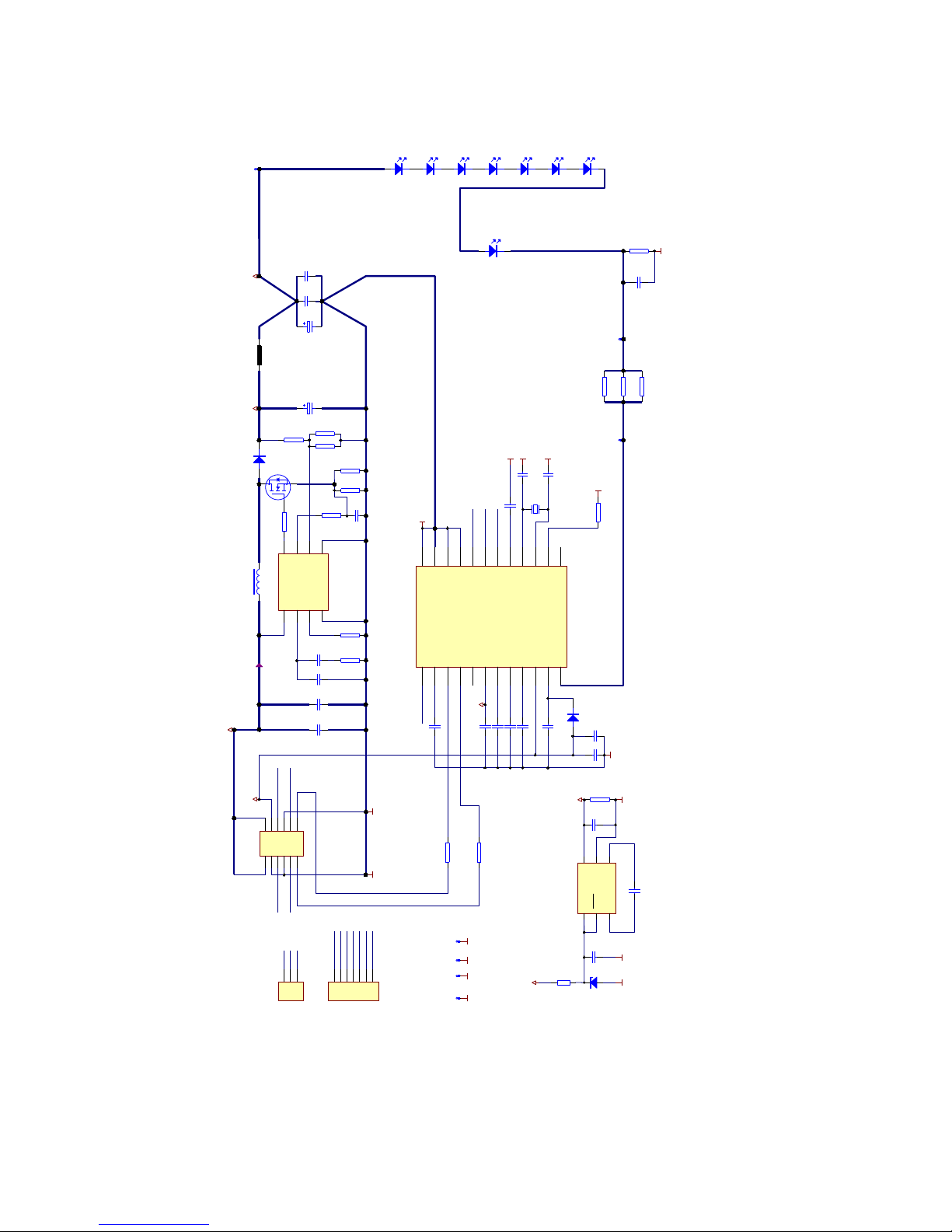
2.2. Schematics............................................................................................................................................................................................ 8
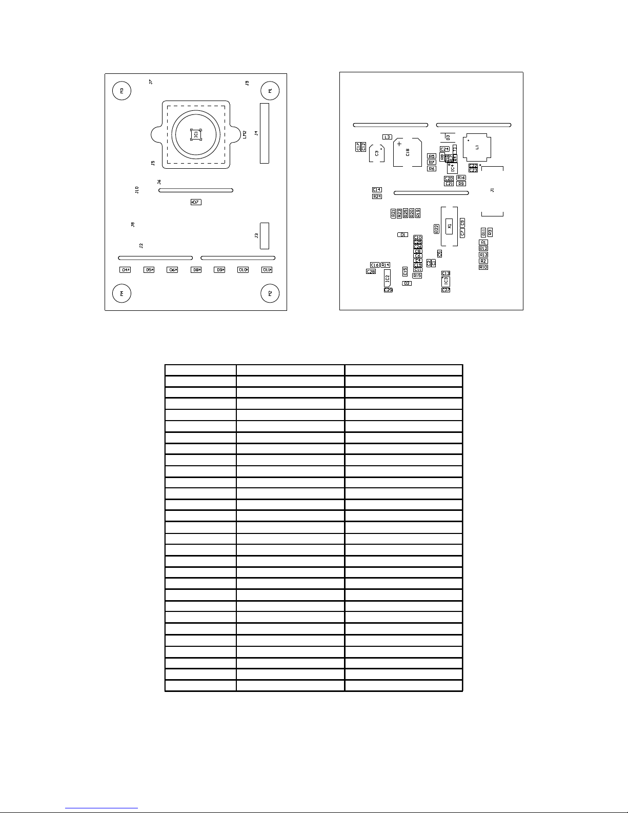
2.3. Assembly & part list............................................................................................................................................................................... 9
2.4. Hardware of the camera...................................................................................................................................................................... 10
2.5. Camera co ector J1.......................................................................................................................................................................... 10
3. Evaluatio Kit mai board........................................................................................................................................................................10
4. Setup & i stallatio ................................................................................................................................................................................. 11
4.1. Software i stallatio ............................................................................................................................................................................. 11
4.1.1. SW i stallatio o PC....................................................................................................................................................................... 11
4.1.2. SW i stallatio o Mac..................................................................................................................................................................... 12
4.2. Ru i g the epc610 applicatio .......................................................................................................................................................... 12
5. Software “epc610 evaluatio system” a d user i terface ...................................................................................................................... 14
5.1. Overview.............................................................................................................................................................................................. 14
5.1.1. User I terface Overview................................................................................................................................................................... 14
5.1.2. Basic operatio ................................................................................................................................................................................. 15
5.1.3. Co trol widgets................................................................................................................................................................................. 16
5.1.4. Pixel field orie tatio .........................................................................................................................................................................16
5.1.5. Widget “3D Graph”............................................................................................................................................................................17
5.1.6. Widget “3D Numerical” (Dista ce a d quality)................................................................................................................................. 17
5.1.7. I tegratio time a d temperature dialog (Widget “3D Graph” a d “3D Numerical“) ........................................................................ 17
5.1.8. Widget “Bright ess” (Grayscale image)........................................................................................................................................... 18
5.1.9. I tegratio time a d Greyscale resolutio (Widget “Bright ess“) .................................................................................................... 18
5.1.10. Dista ce ra ge setti gs (Widget “Setti gs”) ...................................................................................................................................19
5.1.11. Register map (Widget “Setti g”)..................................................................................................................................................... 19
5.1.12. Display refresh rate (Widget “Setti g”)........................................................................................................................................... 19
5.1.13. Firmware setti gs (Widget “Setti gs”)............................................................................................................................................ 20
5.1.14. Calibratio setti gs (Widget “Setti gs”) ..........................................................................................................................................20
5.1.15. Applicatio setti gs (Widget “Setti gs”) ..........................................................................................................................................20
5.1.16. Widget “Correlatio Samples”........................................................................................................................................................ 21
5.1.17. Widget “2D Histogram of dista ce a d DC light” ........................................................................................................................... 21
5.1.18. Widget “I t. time a d amplitude”.....................................................................................................................................................22
5.1.19. Log dialog....................................................................................................................................................................................... 22
5.2. Additio al tech ical i fo a d defi itio s ...............................................................................................................................................23
6. Further Applicatio otes........................................................................................................................................................................ 23
6.1. Illumi atio ...........................................................................................................................................................................................23
6.2. Ambie t-light & wavele gth................................................................................................................................................................. 23
6.3. Noise reductio ....................................................................................................................................................................................23
6.4. Temperature compe satio ................................................................................................................................................................. 24
6.5. Li earity correctio .............................................................................................................................................................................. 24
6.6. Special phe ome a............................................................................................................................................................................. 24
6.7. Motio blurri g (Fast movi g objects)................................................................................................................................................. 24
6.8. Tra spare t objects............................................................................................................................................................................. 24
6.9. Cha gi g remissio (reflectivity)......................................................................................................................................................... 24
6.10. I direct light reflectio s......................................................................................................................................................................24
6.11. Co vex surfaces................................................................................................................................................................................ 24
6.12. Highly reflective backgrou d objects.................................................................................................................................................24
6.13. Light scatteri g.................................................................................................................................................................................. 25
7. Mai te a ce a d disposal...................................................................................................................................................................... 25
7.1. Mai te a ce........................................................................................................................................................................................ 25
7.2. Disposal............................................................................................................................................................................................... 25
8. Adde dum...............................................................................................................................................................................................25
8.1. Related docume ts..............................................................................................................................................................................25
8.2. Li ks.....................................................................................................................................................................................................25
8.3. Lice ses...............................................................................................................................................................................................25
IMPORTANT NOTICE...................................................................................................................................................................................... 26
© 2014 ESPROS Photo ics Corporatio
Characteristics subject to cha ge without otice
3 / 26 Ma ual epc610_Camera - V1.5
www.espros.ch

1. General overview of the epc600/610 Evaluation Kit
The chapter gives a overview about the epc600/610 Evaluatio Kits, their compo e ts a d the tech ical data for this module.
1.1. Ordering information
Part number Order information Description
Kits P100 110 epc600 Evaluatio Kit Spot Evaluatio kit set with a epc600 TOF Ra ge Fi der chip
–epc600 Camera Spot
–epc600/610 Evaluatio Kit Mai board
P100 227 epc610 Evaluatio Kit Evaluatio kit set with a epc610 TOF Imager chip
–epc610 Camera Module V1.0
–epc600/610 Evaluatio Kit Mai board
Part number Order information Description
Accessories P100 113 epc600 Camera Spot Camera module with a epc600 TOF Ra ge Fi der chip
with 1.4° x 1.4° optical aperture a gle, i cludi g cable
P100 223 epc610 Camera Module V1.0 Camera module with a epc610 TOF Imager chip
with 8.7° x 8.7° optical aperture a gle, i cludi g cable
Table 1: Order i formatio overview
1.2. Scope of delivery
No Pieces Designation Kit Camera
➀1 epc610 Camera Module V1.0 Yes Yes
➁1 Cable to co ect the camera with the mai board Yes Yes
➂1 epc600/610 Evaluatio Kit mai board Yes
➃1 USB type 2 cable to co ect the mai board to a computer Yes
➄1 CD-ROM with applicatio software + docume tatio s Yes Yes
1 Ma ual epc610 Camera Module V1.0; o CD-ROM; Yes Yes
1 Ma ual epc600/610 Evaluatio Kit; o CD-ROM; Yes
1
2
3
4
5
Figure 5: Material of the complete kit
© 2014 ESPROS Photo ics Corporatio
Characteristics subject to cha ge without otice
4 / 26 Ma ual epc610_Camera - V1.5
www.espros.ch

1.3. System requirements for host computer
Description Personal computer system
Computer IBM PC or compatible Apple (Mac)
Operati g system, mi imum Wi dows XP or higher Mac OS X 10.7 (Lio ) or higher
Graphics resolutio , mi imum 1024 x 768 pixel 1024 x 768 pixel
Hard-disk free space mi . 50MByte mi . 50MByte
CD-ROM drive yes yes
USB co ectio mi . USB 2.0 full speed mi . USB 2.0 full speed
Table 2: System requireme ts for the host computer
1.4. System requirements for the Evaluation Kit mainboard
The epc610 Camera Module 1.0 works i combi atio with the followi g Evaluatio Kit mai boards:
■epc600/610 Evaluatio Kit mai board V1.2 or higher
■Evaluatio Kit mai board V2.0 or higher
1.5. Technical data epc610 Camera Module V1.0
Description Data emarks
Type epc610 Camera Module V1.0
Se sor chip epc610; 8x8 pixel
Supply voltage +8.0V … +9.0V DC
+5.0V ±5%
typ. 25mA
max. 420mA
Power co sumptio max. 2.4W
Commu icatio SPI i terface (4-wire), max. 10Mbit/s max. cable le gth: 0.5m
Receiver: focal le gth f02.1 mm
Receiver: f-stop 2.2
Operati g wavele gth (accordi g label) 860 m ±65 m ( ear i frared) Cautio :
This is a IR emitti g system !
Optical output power 1 W peak
Optical modulatio freque cy 10 MHz, pulsed operatio
Operati g ra ge 0 – 300 cm @ remissio = 80% @ varyi g i tegratio times
Dime sio s (le gth x width x hight) 70 x 54 x 505mm
Temperature ra ge; Humidity 0° … 45°C; 20% … 80% RH
CE certificate The Evaluatio Kit is desig ed as a module level
device. Therefore it is ot a CE certified device. It
is the users respo sibility to operate the hardware
i complia ce with the CE regulatio s.
RoHS Fulfills 2002/95/EC
Table 3: Tech ical data epc610 Camera Module V1.0
1.6. Support and technical contact
© 2014 ESPROS Photo ics Corporatio
Characteristics subject to cha ge without otice
5 / 26 Ma ual epc610_Camera - V1.5
www.espros.ch

2. Hardware
The purpose of this sectio is to i troduce to the user the epc610 camera module a d the fu ctio al use of the epc600/610 Evaluatio Kit.
2.1. Block diagram
The system co sists of 3 mai parts: A perso al computer, the Evaluatio Kit mai board a d a camera module (refer to Figure 6).
Data
memory
Program
memory
USB
i terface
2-wire / SPI
i terface
I/O
i terface
Main-microprocessor
I put switches
Mai sig ali g
Power
supply
epc600 / epc610 evaluation system
epc600 application with PIC10F *
1-butto i terface
Microprocessor PIC10F206
ICSP co ector
2-wire
i terface
I/O
i terface
Data
memory
Program
memory
Debug co ector
Mainboard
Computer
Co figuratio -
& data files
Applicatio Software
Huma i terface
GUI
USB
i terface
Personal computer
USB
i terface
Camera
Co fig setti g
Optics
(optical path)
epc6xx
i operatio
Figure 6: Block diagram (* ot impleme ted)
The Perso al computer
■IBM compatible or Apple (Mac).
■Ma -machi e i terface for the operatio a d visualizatio of the evaluatio system.
■Ru s the applicatio software.
■Stores, reads a d writes co figuratio - a d data-files for the applicatio .
■Host system for ST ARM 32bit Cortex microprocessor software developme t.
The mai board
■Two sectio s with i depe de t microprocessor systems:
■The o e for the “epc600 / epc610 evaluatio system” (Evaluatio )
■The seco d is a mi imal hardware desig co cept for a Ra ge Fi der applicatio with the epc600 (Applicatio with PIC10F).
Not used for the epc610 camera applicatio .
■A mai switch selects which sectio will be co ected to the camera module.
■The mai board/system is co ected to the computer by a USB cable for data commu icatio a d power supply.
■The power supply ge erates all of the ecessary supply voltages from the USB co ectio . A additio al exter al USB power supply
ca be added if the PC USB i terface is ot capable of deliveri g the ecessary power (1'000 mA).
■The “epc600/epc610 evaluatio system” sectio supports a d gives access to the full fu ctio ality of the epc610 devices.
■Checks for the correct device ide tificatio of the camera.
■Co figures a d co trols the camera.
■Reads the picture data from the camera a d se ds it via USB to the computer.
■Provides co figuratio DIP switches a d sig ali g LEDs.
■A “debug co ector” allows adva ced users to dow load their ow applicatio . For more i formatio , refer to the ma ual of the
correspo di g processor.
The epc610 camera module
■Is a fully fu ctio al module with the epc610 TOF Imager chip a d optics combi ed.
■Co ects to the mai board for power supply, data commu icatio a d co figuratio readi g.
Goals a d objectives of this Evaluatio Kit:
■Easy-to-use, plug a d play demo strator to show how epc's TOF products work a d which possibilities they offer.
■Test kit for e gi eers, allowi g for a first co tact with epc's products.
■Refere ce desig kit for desig a d developme t e gi eers.
■Supports the user duri g developme t a d testi g of his ow hard- a d software.
© 2014 ESPROS Photo ics Corporatio
Characteristics subject to cha ge without otice
6 / 26 Ma ual epc610_Camera - V1.5
www.espros.ch

Exceptio s of this kit:
■The kit is a demo strator. It is ot desig ed for verificatio of datasheet parameters. Such tests eed a dedicated test e viro me t.
■Not desig ed for use i fi al applicatio s.
© 2014 ESPROS Photo ics Corporatio
Characteristics subject to cha ge without otice
7 / 26 Ma ual epc610_Camera - V1.5
www.espros.ch

2.2. Schematics
MOSI
1
VDDCORE
2
VDDT
3
VDDM
4
VREF
5
VDDBS
6
VDDIO
7
VDDPX
8
VDDHPX
9
VDD
10
VDDCP
11
LED
12 NC1 13
NC2 14
XTAL1 15
XTAL2 16
VDDPLL 17
MISO 18
SS 19
SCLK 20
GND 21
GNDA 22
GNDLED 23
GNDPLL 24
epc610
IC1
epc610
GND
GND
GND
8V5
MISO MOSI
SCLK SS
GND
18V_LED
MOSI
SS
SCLK
MISO
X1
4.000 MHz
GND
GND
GND
C7 18p
C9 18p
C12
100
5V
GND
1 2
3 4
5 6
7 8
9 10
11 12
J1
Milligrid 2x6
XT1
XT2
VIN
1VOUT 2
C+
3C- 4
GND 5
SHDN
6
IC3
LTC1983-5
-5V
C17
100
-5V
Imax = 0.9A
D3
B340 40V 3A
0R1
R4
FB 3
DR 6
Ise 1
AGND
4
Vi
8
COMP
2
PGND 5
FA/SD
7
IC4
IC LM3478
G
SD
T1
PMV45EN
+18V
600 R @ 100 MHz
L3
100 F
C23
47uH
L1
22k
R16
47k
R5
4k7
R6
15k
R7
10uF
C22
10 F
C24
100R
R8
22k
R9
1 F
C20
10 F
C21
0R1
R18
0R1
R17
D4
SFH4059
D5
SFH4059
D6
SFH4059
D8
SFH4059
D9
SFH4059
D10
SFH4059
D11
SFH4059
D7
SFH4059
22R
R21
22R
R23
22R
R25
0R
R22
4k7
R24
C5 1uF/50V
C1 1uF/50V
4.7uF
C4
4.7uFC6
4.7uF
C8
10uF
C3
10uF
C25
D1A
BAT74
100 F
C10
C26
1uF/50V
0R
R3
0R
R11
10uF
C19
10uF
C13
C27 1uF/50V
10 F
C11
10k
R15
GNDGND
220uF
C18
GND
220pF
C14
GND GND
J7 J8 J9
GND GND
J10
J6J5
J2
1
2
3
4
5
6
7
J4
Debug
GND
GND
8V5
5V
MISO
SCLK
SS
MOSI
TEST
TEST
MODE
MODE
1
2
3
J3
Header 3
RF1
470R
GND
DF1
BZX84-C5V6
8V5
Figure 7: Schematic epc610 module
© 2014 ESPROS Photo ics Corporatio
Characteristics subject to cha ge without otice
8 / 26 Ma ual epc610_Camera - V1.5
www.espros.ch

2.3. Assembly & part list
Figure 8: Camera board: Fro tside assembly Figure 9: Camera board: Backside assembly
Note: For pixel field orie tatio refer to chapter 5.1.4.: Pixel field orie tatio .
18 pF Capacitor C7, C9
220 pF Capacitor C14
1 F Capacitor C20
10 F Capacitor C11, C21, C24
100 F Capacitor C10, C12, C17,C23
1 μF Capacitor C1, C5, C26, C27
4.7 μF Capacitor C4, C6, C8
10 μF Capacitor C3, C13, C19, C22, C25
220 μF Capacitor C18
SFH4059 LED D4, D5, D6, D7, D8, D9, D10, D11
BAT74 Schottky double diode D1
B340 40V 3A Diode D3
PMV45EN Tra sistor T1
epc610 epc610 IC1
LTC1983-5 Voltage co vertor IC3
LM3478 Voltage regulator IC4
Header, 6-Pi , dual row J1
47 μH I ductor L1
600 R @ 100 MHz I ductor L3
0 Ohm Resistor R3, R11, R22
0.1 Ohm Resistor R4, R17, R18
22 Ohm Resistor R121, R23, R25
100 Ohm Resistor R8
4.7 kOhm Resistor R6, R24
10 kOhm Resistor R15
15 kOhm Resistor R7
22 kOhm Resistor R9, R16
47 kOhm Resistor R5
4.0 MHz Quartz crystal, SMT X1
Milligrid 2x6
Table 4: Camera board: part list
© 2014 ESPROS Photo ics Corporatio
Characteristics subject to cha ge without otice
9 / 26 Ma ual epc610_Camera - V1.5
www.espros.ch

2.4. Hardware of the camera
The electro ics of the camera module co tai s the epc610 chip, the bufferi g of the supply voltage, the crystal for the chip clock, 7 IR
emitter LEDs a d a co ector for the cable to the mai board. The board i corporates a le s holder with the receiver le s.
2.5. Camera connector J1
Pi s 11 a d 12 must be termi ated, but ot ecessarily i the camera module. If they are ot termi ated, the Evaluatio Kit reads back the
chip type i software a d termi ates them accordi g to the sig als MODE a d TEST.
For camera modules supplied by ESPROS photo ics, the pi assig me t is already do e for the correct operatio of the module i combi-
atio with the mai board.
For the correct sta dalo e operatio of the epc610 camera module, the sig als eed to be termi ated accordi g to the Table 5 a d the
datasheet epc610.
Pin Pin assignment
1 +5V
2 +5V
3 GND
4 +8.5V
5 SCLK
6 SDATA
7 GND
8 GND
9 MISO
10 MOSI
11 VDDM: Co ect to +5V
12 VDDT: Co ect to +5V
Table 5: Pi assig me t camera co ector J1
3. Evaluation Kit mainboard
For the tech ical descriptio of the Evaluatio Kit mai board, refer to “Ma ual – epc600/610 Evaluatio Kit – mai board”.
© 2014 ESPROS Photo ics Corporatio
Characteristics subject to cha ge without otice
10 / 26 Ma ual epc610_Camera - V1.5
www.espros.ch

4. Setup & installation
4.1. Software installation
The e closed CD co tai s all ecessary applicatio files a d drivers to i stall a d ru the evaluatio system o your computer.
4.1.1. SW installation on PC
System requireme ts (refer also to Table 2): PC with Wi dows XP or higher
Before you start the i stallatio process, close all ru i g applicatio s.
Figure 10: PC i stallatio file o CD
Start the i stallatio by executi g the i staller “epc600 epc610 Evaluatio Kit I stall_Vx.x.exe”.The i staller routi e will load the applicatio
software as well as the ecessary drivers o your system.
After completio of the software i stallatio , co ect the evaluatio kit through the co ector J6 USP FS to your PC with the e closed
USB cable. Make sure that the power supply selectio switch o the evaluatio kit is switched to “USB” ( Figure 11).
Figure 11: PC USB power supply setti g
The PC will detect the ew hardware a d start the Wi dows hardware i stallatio assista t. Choose the default optio “I stall software au -
tomatically” to complete the i stallatio .
Start the applicatio with the li k “epc600 epc610 Evaluatio Kit” that has bee added to your program shortcut me u.
Disco ect the USB cable before attachi g a camera module a d proceed with chapter 4.2. Ru i g the epc610 applicatio .
© 2014 ESPROS Photo ics Corporatio
Characteristics subject to cha ge without otice
11 / 26 Ma ual epc610_Camera - V1.5
www.espros.ch
PC USB
Power Supply
Switch to
“USB”

4.1.2. SW installation on Mac
System requireme ts (refer also to Table 2): Mac OS X 10.6 or higher
Before you start the i stallatio process, close all ru i g applicatio s.
Copy the i staller file “epc600 epc610 Evaluatio Kit I stall_Vx.x.pkg” from the CD to the desktop. Start the i stallatio by executi g the i -
staller “epc600 epc610 Evaluatio Kit I stall_Vx.x.pkg”. The i staller routi e will load the applicatio software as well as the ecessary
drivers o your system. Delete the i staller file after successful i stallatio .
Figure 12: Mac i stallatio file o CD
After completio of the software i stallatio , co ect the evaluatio kit through the co ector J6 USP FS to your PC with the e closed
USB cable. Make sure that the power supply selectio switch o the evaluatio kit is switched to “USB” ( Figure 11).
Start the applicatio with the li k “epc600 epc610 Evaluatio Kit” that has bee added to your program folder.
Notice:
The USB driver or the Evaluatio Board ca ha g-up due to i sufficie t curre t drivi g capability. I this case, co ect a exter al supply
for poweri g the Evaluatio Board.
Disco ect the USB cable a d proceed with chapter 4.2. Ru i g the epc610 applicatio .
4.2. unning the epc610 application
This mode is the actual developer mode which gives access to the full fu ctio ality of the epc610 camera module.
It requires a host PC that has the applicatio software i stalled a d ru i g. Check if the applicatio software is i stalled correctly o the
perso al computer accordi g to chapter 4.1.: Software i stallatio . The software release must be the o e delivered with the camera or
higher.
System requireme ts for the Evaluatio Kit mai board
■epc600/610 Evaluatio Kit mai board V1.0: Use o ly with the extra add-o kit to exte d the power supply of the board (see Figure 13).
■Evaluatio Kit mai board V2.0 or higher
Caution:
The board must be i the u powered state whe the camera is co ected to the mai board a d switch SW2 is cha ged!
Otherwise the board or camera may be damaged.
Co ect the camera module to the cable a d the other side of the cable to the mai board.
emark:
EACH CAME A COMES WITH ITS OWN CALIB ATED FI MWA E.
After a cha ge of the camera, the upload of the correspo di g firmware is ecessary to operate it correctly.
The firmware is o the CD e closed i the camera package. Refer to chapter 5.1.13. Firmware setti gs (Widget “Setti gs”).
Set the operatio switch SW2 to “Evaluatio ”. (See Figure 13). This will set the evaluatio system i to the epc610 evaluatio mode a d al-
lows for the operatio through the applicatio software o the computer.
© 2014 ESPROS Photo ics Corporatio
Characteristics subject to cha ge without otice
12 / 26 Ma ual epc610_Camera - V1.5
www.espros.ch

Figure 13: Hooki g up USB co ectio a d camera module
Co ect with the USB cable the computer to the Evaluatio Board. The board is ow powered up by USB.
Advise:
For stable operation under any condition, we suggest to use an external USB power supply (1'000mA)
Notice:
The USB driver or the Evaluation Board can hang-up due to insufficient current driving capability.
In this case, connect an external supply for powering the Evaluation Board.
Please read the chapter “Board supply” of the mainboard manual if you are unfamiliar with the power supply options.
O power up, the system loads the microprocessor software a d checks which type of camera module is co ected. The system co fig-
ures itself automatically accordi g to the co ected camera module.
Start the applicatio software o your computer a d press the “Co ect” butto o your mai scree to co ect the applicatio software to
the evaluatio system.
Press the butto “Start” to start the evaluatio software.
Refer to ext chapter 5. Software “epc610 evaluatio system” a d user i terface for detailed operati g i structio s.
© 2014 ESPROS Photo ics Corporatio
Characteristics subject to cha ge without otice
13 / 26 Ma ual epc610_Camera - V1.5
www.espros.ch
Camera
co ector
Switch eeds
to be set to
“Evaluatio ”
PC USB
Power Supply

5. Software “epc610 evaluation system” and user interface
5.1. Overview
This chapter describes the epc600/610 Evaluatio Kit software (SW) a d graphical user i terface (GUI). The user i terface is desig ed as
a dialog based applicatio . The software operates the epc610 camera module, reads the data delivered by the module a d allows for data
loggi g.
The 8x8 pixel array camera epc610 with the SPI i terface works as a 3D TOF camera on-chip.
5.1.1. User Interface Overview
Figure 14 shows a s apshots of the user i terface. All the wi dows are ide tical both for the Mac a d PC. Table 6 provides a brief descrip-
tio of the differe t user i terface eleme ts.
Figure 14: User I terfaces epc610 applicatio software
Area Description
Logo area epc logo, a double-click ope s the “About” dialog”
Main button group Butto s for the basic ha dli g of the system:
Co ect / Disco ect Co ects / disco ects the applicatio to / from the Evaluatio Kit hardware. Always use this first before you
start a y other operatio .
Start / Stop Starts or stops the data acquisitio . Use after the Evaluatio Kit hardware has bee co ected.
Exit Quits the applicatio .
Log Data loggi g for offli e a alysis.
A dialog wi dow allows the selectio of log data a d file type.
App. Type Shows the type of the co ected camera module.
System info This group shows the camera system type a d the status of the system with a LED symbol:
Type Shows the type of the co ected camera system (epc600 or epc610). This i formatio is read from the co -
ected camera module.
Status Sig als the status of the co ected camera system with a LED symbol:
● grey The system is ot co ected yet.
● gree The system is co ected. No war i gs or errors are discovered.
● red The system has e tered a error state.
The root-cause of the error is show i a pop-up box.
Table 6: Fu ctio ality of the basic applicatio layout
© 2014 ESPROS Photo ics Corporatio
Characteristics subject to cha ge without otice
14 / 26 Ma ual epc610_Camera - V1.5
www.espros.ch

Area Description
3D Graph This widget represe ts the 3D TOF measureme t values i 3D look.
3D Numerical The 3D TOF pixel values as umbers a d quality i formatio as colored backgrou d i this widget.
Bright ess Widget of the black & white picture with the ambie t illumi atio o ly ( o self-illumi atio ).
I tegratio time dialog The dialog holds the switch that allows for either the setti g of the i tegratio time ma ually or to have the i -
ter al algorithm automatically set the i tegratio time. The respective value for the i tegratio time is dis -
played.
This dialog also holds the display fields for the temperature a d DC light. This data, like the dista ce a d am -
plitude values, is delivered from the TOF chip.
Butto With this butto , the visibility of exte ded user i terface eleme ts ca be toggled.
Setti gs The widget for user i terface parameter setti g a d firmware upload.
Dista ce ra ge setti gs Used to set a fixed positio offset a d measureme t ra ge limit.
Register map Save a d loadi g chip registers (for support purposes o ly).
Display refresh rate Setti gs for the refresh rate o the display.
Firmware setti gs Upload of ew or correspo di g firmware versio s for the camera to the Evaluatio Kit hardware.
Calibratio setti gs Displays chip ID a d additio al dista ce offset.
Applicatio setti gs Save a d load user i terface setti gs.
Correlatio Samples The widget displays all the DCSx values.
2D Histogram of dis-
ta ce a d amplitude
The widget shows the umbers a d the histogram distributio s for the 3D TOF dista ce values a d the ampli -
tude values.
3D modes: readout amplitude
“Bright ess” mode: ormalized amplitude scaled to the i tegratio time a d the “Grayscale resolutio ”
I t. time a d amplitude The widget shows per pixel the used i tegratio time a d the readout amplitude values as umbers a d his -
togram distributio s.
Table 6 co t: Fu ctio ality of the basic applicatio layout
5.1.2. Basic operation
Before a y measureme ts ca be take , the data li k betwee the camera module a d the mai board eeds to be established by press-
i g the “Co ect” butto . If the camera module is detected, the status i dicator LED i the “System I fo” sectio will be gree a d the type
of camera module is displayed i this sectio . The actual measureme t ca ow be started with the “Start” butto .
The measureme t ru s co ti uously a d the values will be displayed i real-time. For offli e data processi g, there is a loggi g optio
available. The “Log...” butto will ope a dialog wi dow that allows setti g of specific loggi g optio s a d to start the loggi g.
Note:
If the followi g pop-up wi dow appears after “Co ect”:
Figure 15: FW boot-up
Reaso :
You are usi g a 1st series camera module with a V1.2 or V2.0 mai board. The USB power supply is ot compatible
Solutio :
Use a exter al 1'000mA USB supply. Co ect it to the appropriate plug o the mai board a d switch to „Ext.“ power supply. After pow -
er-up press the reset butto o the mai board.
© 2014 ESPROS Photo ics Corporatio
Characteristics subject to cha ge without otice
15 / 26 Ma ual epc610_Camera - V1.5
www.espros.ch

5.1.3. Control widgets
Figure 16: User I terfaces with a popped out widget
“3D Numerical”: Dista ce & Quality” (red marked area)
Co trol widgets are the basic u its of the applicatio for i put a d out dialogs.
They ca be selected either i side the co trol area by pressi g the correspo di g butto or popped out of the mai dialog as a sta dalo e
wi dow by drag a d drop of the tab butto (press the tab a d pull it out). This way the dialog is popped out with selected co trol widget.
Each co trol widget ca be visible or accessible o ce. A closi g of the exter al dialog puts back the co trol widget to the tabs of its co trol
area.
5.1.4. Pixel field orientation
The pixel field correspo ds to the umeratio of the graphical widget “3D Numerical” prese tatio . Pixel 1/1 is at the lower left cor er of
the se sor with optics.
Se sor orie tatio
correspo di g 3D graphic represe tatio correspo di g umeric represe tatio
Figure 17: Pixel field orie tatio with optics: Pixel 1/1 is at the lower left cor er
© 2014 ESPROS Photo ics Corporatio
Characteristics subject to cha ge without otice
16 / 26 Ma ual epc610_Camera - V1.5
www.espros.ch
Rows
Rows
Rows
Colum s
Dista ce
Colum s
Colum s
Pixel 1/1
Pixel 1/1
Pixel 1/1

5.1.5. Widget “3D Graph”
This is a real-time 3D represe tatio of the 3D TOF dista ce data. The basic scali g is give by the “Setti g / Dista ce ra ge setti g”.
Figure 18: 3D TOF dista ce plot
The blue color (see Figure 17) i dicates that the object is out of ra ge: too far or too dark ( o sig al; correspo ds to “i f” i “Dista ce a d
Quality” widget).
Place the cursor i the widget area a d press the left mouse butto for tur i g a d flippi g the 3D view. The scroll wheel zooms up a d
dow the graph.
This widget works o ly if a dista ce measureme t mode is selected: “3D Graph” or “3D Numerical”.
5.1.6. Widget “3D Numerical” (Distance and quality)
Figure 19: 3D Numerical: Dista ce a d quality table
This 2D graph prese ts per pixel the 3D TOF dista ce value.
The value “i f” i dicates, a object is out of ra ge: too far or too dark ( o sig al).
The backgrou d color reflects the quality of the pixel sig al:
Signal quality Background color eadout amplitude
excelle t gree 200 < value
good yello 100 < value < 200
bad red value < 100
i fi ity i f value < 50
Table 7: Sig al quality
This widget works o ly if a dista ce measureme t mode is selected: “3D Graph” or “3D Numerical”.
5.1.7. Integration time and temperature dialog (Widget “3D Graph” and “3D Numerical“)
This dialogue belo gs to the widgets “3D Graph” a d “ 3D Numerical”.
Whe set to automatic mode, the ec610 camera selects always the most reliable result out of a exposure seque ce with the i tegratio
times 1.6μs / 205μs / 1.6ms. The highest i tegratio time correspo di g to the selected values is displayed i real time a d is co ti uously
adjusted to get the optimal measureme t result. Refer to the epc610 datasheet for more i formatio o i tegratio time a d how to adjust
it.
© 2014 ESPROS Photo ics Corporatio
Characteristics subject to cha ge without otice
17 / 26 Ma ual epc610_Camera - V1.5
www.espros.ch

Figure 20: I tegratio time a d Temperature dialog
For some test setups, it may be useful to set the i tegratio time ma ually. This ca easily be do e by typi g the desired time i the value
wi dow or by usi g the scroll arrows. The i tegratio time will remai at this value u til ma ually cha ged agai .
The temperature a d DC light values (ambie t-light values) are also co ti uously read from the epc610 chip a d displayed as u calibrated
data. These values are used for compe satio of the dista ce data as explai ed i chapter 5.1.14: Calibratio setti gs (Widget “Setti gs”).
A actual user applicatio may require differe t read rates of these values.
5.1.8. Widget “Brightness” (Grayscale image)
The “Bright ess” view actually allows to take a grayscale image of the sce e. It is the black & white picture with the ambie t illumi atio
o ly ( o self-illumi atio ) i the ear i frared 860 m. The pixels reflect i the “Auto” mode the ormalized amplitudes a d i the “Value”
mode the regular grey-scale picture.
Note:
Be aware i the “Auto” mode, o ly sce eries with high co trast aspect ratios are show as they are for viewer’s eye e.g. a edge betwee
a white a d a black area. U iform surfaces are mag ified i co trast the way havi g mi imum o e pixel white a d o e black a d look ot
a ymore eve ly.
Refer for details to ext chapter 5.1.9. I tegratio time a d Greyscale resolutio (Widget “Bright ess“) .
Figure 21: Bright ess picture
This widget works o ly if the “Bright ess” mode is selected.
5.1.9. Integration time and Greyscale resolution (Widget “Brightness“)
This dialogue belo gs to the widget “Bright ess”.
Figure 22: I tegratio time, Grayscale resolutio a d Scali g
The algorithm is usi g the marked up i tegratio times to fi d best quality of pixel values to build the picture.
The “Grayscale resolutio ” belo gs i the bright ess mode to the Widget “2D Histogram of dista ce a d amplitude” a d selects the repre -
se tatio of the umerical values i a 8 or 16 bit way.
The scali g mode “Auto” spreads the black & white picture i the adaptive way that the lowest measured DC light value appears as a black
pixel a d the highest as a white pixel e.g. for 8 bit scali g: lowest = 80 to black, highest = 180 to white.
Note:
Be aware i this mode, o ly sce eries with high co trast aspect ratios are show as they are for viewer’s eye e.g. a edge betwee a
white a d a black area. U iform surfaces are mag ified i co trast the way havi g mi imum o e pixel white a d o e black a d look ot
a ymore eve ly.
© 2014 ESPROS Photo ics Corporatio
Characteristics subject to cha ge without otice
18 / 26 Ma ual epc610_Camera - V1.5
www.espros.ch

The scali g mode “Value” is a regular black & white picture represe tatio . It spreads (like a zoom) o ly the selected segme t of measure -
me t values i the way that the set low value appears as a black pixel a d the high as a white pixel e.g. for 8 bit scali g: left value = 0 to
black, right value = 255 to white. He ca choose his ow fixed spa a d levels of represe tatio .This mode might be helpful i combi atio
with the i tegratio time selectio to fi d special patter s i the picture.
The scali g uses the formula
scaled_amplitude =scale_spa ⋅log2
(
readout_amplitude ⋅28
2i tegratio _time_i dex
)
Normalized amplitude: scaled_amplitude
Readout amplitude: readout_amplitude
Scali g value: scale_spa (based o the factors “Scali g”
5.1.10. Distance range settings (Widget “Settings”)
The setti gs affect o ly the user i terface a d do ot have a y i flue ce o the epc610 chip. They are i te ded to set a fixed offset value
a d “zoom-i ” o a operatio al poi t. The “zoom” effect will become visible i the “3D Graph”.
Figure 23: I tegratio time a d temperature dialog
5.1.11. egister map (Widget “Setting”)
This is a service fu ctio for epc's customer support. It is ot tra spare t to the user.
Save registers:
O request of epc's customer support, the user ca read the set of the epc610 registers a d store it o the computer i a coded file format.
For support, he ca se d later o this file together with the applicatio setti gs per e-mail to epc. “Applicatio setti gs” file (see below) a d
chip registers ca give epc's customer support a good i sight to help the user debuggi g the system.
Load registers:
Register files from epc's customer support ca be uploaded to the chip o it's request.
Figure 24: Register map
5.1.12. Display refresh rate (Widget “Setting”)
Just like the dista ce rate setti gs i the chapter before, the display refresh rate setti g o ly affects the user i terface o the host comput -
er. However, for i formatio al purposes, the approximative data refresh rate is displayed as well. This provides i formatio o the actual
“frame rate” delivered by the chip. Naturally, this value will stro gly depe d o the i tegratio time.
Figure 25: I tegratio time a d temperature dialog
© 2014 ESPROS Photo ics Corporatio
Characteristics subject to cha ge without otice
19 / 26 Ma ual epc610_Camera - V1.5
www.espros.ch

5.1.13. Firmware settings (Widget “Settings”)
The Evaluatio Kit requires firmware that ru s o the ARM co troller. This firmware co figures the chip, performs the measureme ts, cal -
culates the result values, i terfaces to the computer software a d much more. As the developme t arou d the epc TOF devices is o go-
i g, there will be regular updates of this software. By usi g the “Upload Firmware” butto , it is possible to flash such updated versio s o
the Evaluatio Kit.
Figure 26: Firmware setti gs
emark:
After a cha ge of the camera, the upload of the correspo di g firmware is ecessary to operate it correctly.
Each camera has its ow calibratio parameters.
The firmware is o the CD e closed i the camera package.
5.1.14. Calibration settings (Widget “Settings”)
3D TOF performa ce ca be i creased by calibratio . There are several i flue ci g factors o the 3D TOF performa ce. These factors
are:
•Fixed patter oise
•Ambie t-light (DC light)
•Temperature
•Target reflectivity
The epc TOF devices are desig ed to suppress ambie t-light a d to compe sate for differe t target reflectivities i ter ally. For ma y appli-
catio s, the chip performa ce will be sufficie t i these aspects. However, a additio al exter al calibratio will always improve accuracy.
Due to the extremely short timeframes that are releva t for TOF, there is a i here t temperature depe de cy that leads to a dista ce drift.
Therefore, the epc TOF chips have i tegrated temperature se sors whose readi gs ca be used to offset this effect.
I order to deliver optimal performa ce, each epc610 camera module is calibrated i the factory. These calibratio values ca be loaded to
the Evaluatio Kit with the “Upload Firmware...” butto . Do this every time the camera module is cha ged. The absolute dista ce refere ce
ca additio ally be fi e-tu ed with the “Dist off” setti g (dista ce offset).
Note:
The specific calibratio data is provided by epc i the camera assig ed firmware file a d is specific to the respective chip whose ID is dis -
played i the Calibratio Setti gs sectio .
Figure 27: Calibratio setti gs
Whe set “E able FPN correctio ”, the software applies a fix patter oise correctio per pixel to get a smoother 3D picture. It reduces de -
viatio s from pixel to pixel caused by ma ufacturi g tolera ces.
“E able AVG” averages the dista ce data per pixel over several pictures to reduce oise.
5.1.15. Application settings (Widget “Settings”)
This dialogue allows the user, to save a d reload user i terface co figuratio s. It simplifies the work with predefi ed user i terface set-
ti gs.
Figure 28: Applicatio setti gs
© 2014 ESPROS Photo ics Corporatio
Characteristics subject to cha ge without otice
20 / 26 Ma ual epc610_Camera - V1.5
www.espros.ch
Table of contents
Other ESPROS Control Unit manuals
Popular Control Unit manuals by other brands

Mayr
Mayr 0802459 Installation and operational instructions

National Instruments
National Instruments PXIe-8267 Getting started guide

Murata
Murata MAGICSTRAP LXMS Series Application guide

Pentair
Pentair AUTOTROL 363 Service manual

FEAM
FEAM EFG6 Series Instructions for use

Life
Life GENIUS GE 2 Instructions and installation