EM Acoustics Di06 Operational manual

Di06 / Di10 / Di20
advanced installation amplifier
Product User Manual
v1 July 2023
liberating audio

2
Contents
IMPORTANT SAFETY INSTRUCTIONS ................................................................................................................5
CONSIGNES DE SÉCURITÉ IMPORTANTES.........................................................................................................6
COMPLIANCE.........................................................................................................................................................8
FOR CUSTOMERS IN EUROPE..........................................................................................................................8
FOR CUSTOMERS IN THE USA.........................................................................................................................9
FOR CUSTOMERS IN THE CANADA.............................................................................................................. 10
Thanks and Unpacking...................................................................................................................................... 11
Unpacking the Di Series Amplifier............................................................................................................... 11
INSTALLATION INSTRUCTIONS ....................................................................................................................... 12
Mechanical Installation................................................................................................................................. 12
AC Power Connection.................................................................................................................................... 13
Introduction and Key Features........................................................................................................................ 14
Introduction.................................................................................................................................................... 14
Key Features.............................................................................................................................................. 14
Audio Connections ............................................................................................................................................ 17
Input Connections ......................................................................................................................................... 17
Using unbalanced connections.................................................................................................................... 17
Amplifier Output Connections ..................................................................................................................... 18
Load Matching................................................................................................................................................ 18
Panel Layouts .................................................................................................................................................... 19
Operation............................................................................................................................................................ 21
Starting up the unit....................................................................................................................................... 21
Overview of Modules, Presets Components and Snapshots ................................................................... 21
Drive Module Presets.................................................................................................................................... 22
Component Presets....................................................................................................................................... 22
Factory Module Presets................................................................................................................................ 23
Storing Module Presets ............................................................................................................................ 23
Recalling Module Presets ......................................................................................................................... 23
Recalling Components .............................................................................................................................. 23
Input................................................................................................................................................................ 23
AES3 Inputs................................................................................................................................................ 23
Networked Audio (Dante) Inputs............................................................................................................. 24
Automatic Input Selection (Fallover) ...................................................................................................... 24

3
Gain and Polarity ....................................................................................................................................... 24
Delay ........................................................................................................................................................... 24
High Pass Filter.......................................................................................................................................... 25
Parametric Equalisation............................................................................................................................ 25
FIR Shelving EQ ......................................................................................................................................... 25
Parametric Filters ...................................................................................................................................... 25
Routing ....................................................................................................................................................... 25
Output............................................................................................................................................................. 26
Gain and Polarity ....................................................................................................................................... 26
Delay ........................................................................................................................................................... 26
High and Low pass Filters ........................................................................................................................ 26
LIR Crossover Filtering.............................................................................................................................. 26
Parametric Equalisation and All-Pass Filters ......................................................................................... 26
Limiters....................................................................................................................................................... 27
Bridge.......................................................................................................................................................... 28
Routing ....................................................................................................................................................... 28
Stereo Linking............................................................................................................................................ 29
IP Address................................................................................................................................................... 29
Store Snapshot .......................................................................................................................................... 29
ECO.............................................................................................................................................................. 30
External Breaker Protection (EBP).............................................................................................................. 30
Ethernet.......................................................................................................................................................... 30
Ethernet configurations ........................................................................................................................... 30
DHCP ........................................................................................................................................................... 30
AUTO-IP ...................................................................................................................................................... 30
Static-IP ...................................................................................................................................................... 31
IP Troubleshooting.................................................................................................................................... 31
Snapshots....................................................................................................................................................... 31
AUX Port A ..................................................................................................................................................... 31
Fault Relay A.................................................................................................................................................. 32
AUX Port B ..................................................................................................................................................... 32
Check Relay B ................................................................................................................................................ 32
AUX Port C...................................................................................................................................................... 32
RS232/ RS485............................................................................................................................................... 32
Latency delay................................................................................................................................................. 33

4
Input/Output Latencies ............................................................................................................................ 33
Processing Latencies ................................................................................................................................ 33
Overlay Flush ................................................................................................................................................. 34
Revert to Factory Settings........................................................................................................................... 34
Protection Systems....................................................................................................................................... 34
Summary of Protection Indication................................................................................................................... 34
Incident Reporting......................................................................................................................................... 35
Performance Logging.................................................................................................................................... 35
Tipi Third Party Interface ............................................................................................................................. 36
Processing Block Diagram ................................................................................................................................ 37
EQ and Filter Response Graphs ....................................................................................................................... 38
Technical Specifications................................................................................................................................... 41
General............................................................................................................................................................ 41
Audio............................................................................................................................................................... 41
Digital processing.......................................................................................................................................... 41
Power Output................................................................................................................................................. 42
Power supply ................................................................................................................................................. 42
Protection systems ....................................................................................................................................... 42
System protection......................................................................................................................................... 42
Power distribution protection systems...................................................................................................... 43
Monitoring and logging................................................................................................................................. 43
Physical........................................................................................................................................................... 43
Options ............................................................................................................................................................... 43

5
IMPORTANT SAFETY INSTRUCTIONS
1Read these instructions.
2Keep these instructions.
3Heed all warnings.
4Follow all instructions.
5Do not use this apparatus near water.
6Clean only with dry cloth.
7Do not block any ventilation openings. Install in accordance with the manufacturer's
instructions.
8Do not install near any heat sources such as radiators, heat registers, stoves or other
apparatus (including amplifiers) that produce heat.
9Do not defeat the safety purpose of the polarized or grounding type plug. A polarized
plug has two blades with one wider than the other. A grounding type plug had two
blades and a third grounding prong. The wide blade or the third prong are provided for
your safety. If the provided plug does not fit into your outlet, consult an electrician for
replacement of the obsolete outlet.
10 Protect the power cord from being walked on or pinched particularly at plugs,
convenience receptacles and the point where they exit from the apparatus.
11 Only use attachments / accessories specified by the manufacturer.
12 Use only with the cart, tripod, bracket or table specified by the manufacturer, or sold
with the apparatus. When a cart is used, use caution when moving the cart / apparatus
combination to avoid injury from tip-over.
13 Unplug this apparatus during lightning storms or when unused for long periods of
time.
14 Refer all servicing to qualified service personnel. Service is required when the apparatus
has been damaged in any way, such as power-supply cord or plug damaged, liquid has
been spilled or objects have fallen into the apparatus, this apparatus has been
exposed to rain or moisture, does not operate normally, or has been dropped.
SAFETY WARNING
Do not remove any covers, loosen any fixings or allow items to enter any aperture.
SAFETY WARNING
The rear of the product may get hot. Avoid direct skin contact during operation and for at
least 5 minutes after power has been isolated.
SAFETY WARNING
The product must only be positioned at floor level when operated in a horizontal position.

6
CONSIGNES DE SÉCURITÉ IMPORTANTES
1. Lisez ces instructions.
2. Conservez ces instructions.
3. Respectez tous les avertissements.
4. Suivez toutes les instructions.
5. Ne pas utiliser cet appareil près de l'eau.
6. Nettoyer uniquement avec un chiffon sec.
7. Ne pas bloquer les ouvertures de ventilation. Installer conformément aux instructions
du fabricant.
8. Ne pas installer près de sources de chaleur telles que radiateurs, registres de chaleur,
poêles ou autres appareils (y compris les amplificateurs) qui produisent de la chaleur.
9. Ne supprimez pas le dispositif de sécurité de la fiche polarisée ou mise à la terre. Une
fiche polarisée possède deux lames dont l'une est plus large que l'autre. Une prise de
terre a eu deux lames et une troisième broche de terre. La lame large ou la troisième
broche sont fournies pour votre sécurité. Si la fiche fournie ne rentre pas dans votre
prise, consultez un électricien pour remplacer la prise obsolète.
10.Protéger le cordon d'alimentation soit écrasé ou pincé, particulièrement au niveau des
fiches, des prises et le point où ils sortent de l'appareil.
11.Utilisez uniquement les accessoires spécifiés par le fabricant.
12.Utilisez uniquement le chariot, le trépied, le support ou la table spécifiés par le
fabricant, ou vendu avec l'appareil. Quand un chariot est utilisé, soyez prudent lorsque
vous déplacez l'ensemble chariot / appareil afin d'éviter toute blessure en cas de
chute.
13.Débranchez cet appareil pendant les orages ou lorsqu'il n'est pas utilisé pendant de
longues périodes de temps.
14.Adressez-vous à un personnel qualifié. Une réparation est requise lorsque l'appareil a
été endommagé de quelque façon que ce soit le cordon d'alimentation ou la fiche
endommagé, du liquide a été renversé ou des objets sont tombés dans l'appareil, cet
appareil a été exposé à la pluie ou à l'humidité, ne fonctionne pas normalement, ou s'il
est tombé.
15.Le dispositif ne doit pas être exposé à des gouttes ou des éclaboussures et aucun
objet rempli de liquides, tels que des vases, doit être placé sur l'appareil.
16.Déconnexion permanente de l'alimentation secteur doit être atteint en supprimant le
connecteur du cordon fourni à l'arrière de l'unité. Ce connecteur doit être facilement
utilisable.

7
AVERTISSEMENT DE SECURITE
Ne retirez pas les couvercles, ne desserrez pas les fixations et ne laissez aucune pièce
s'introduire dans les ouvertures.
AVERTISSEMENT DE SECURITE
Le radiateur arrière de cet appareil devient chaud. Evitez tout contact direct avec la peau
pendant le fonctionnement et au moins 5 minutes après la mise hors tension de l'appareil.
AVERTISSEMENT DE SECURITE
Le produit ne doit être positionné au niveau du sol lorsqu'il est utilisé en position horizontale.

8
COMPLIANCE
FOR CUSTOMERS IN EUROPE
This product complies with both the LVD (electrical safety) 73/23/EEC and EMC
(electromagnetic compatibility) 89/336/EEC directives issues by the commission of the
European community.
Compliance with these directives implies conformity with the following European standards:
EN60065 Product safety
EN55103-1 EMC emissions
EN55103-2 EMC immunity
This product is intended for the following electromagnetic environments: E1, E2; E3 & E4.
THIS PRODUCT MUST BE EARTHED. Use only a flexible cable or cord with a green and yellow
core which must be connected to the protective earthing terminal of a suitable mains plug or
the earthing terminal of the installation. The cord must be a maximum of 2m long, have a
2.5mm2CSA, a 300/500V rating and comply with EN50525-2-11 / H05W-F.
THIS PRODUCT IS DESIGNED FOR PERMANENT INSTALLATION. It must be fitted in to a 19”
rack enclosure and not operated unless so installed. The rack enclosure should be open at the
front and back to allow free ventilation and movement of air through the product.

9
FOR CUSTOMERS IN THE USA
This product complies with UL60065 7th edition.
THIS PRODUCT MUST BE EARTHED. Use only a flexible cable or cord with a green or green /
yellow core which must be connected to the protective earthing terminal of a suitable mains
plug or the earthing terminal of the installation. The cord must be a maximum of 6’ long, be
14AWG, have a rating SJ, SJT, SJE or 300/500V H05W-F and be marked VW-1.
THIS PRODUCT IS DESIGNED FOR PERMANENT INSTALLATION. It must be fitted in to a 19”
rack enclosure and not operated unless so installed. The rack enclosure should be open at the
front and back to allow free ventilation and movement of air through the product.
DECLARATION OF CONFORMITY WITH FCC RULES
We, Linea Research Ltd. of 1 Marquis Business Centre, Royston Road, Baldock, Hertfordshire,
SG7 6XL, England, declare under our sole responsibility that this family of devices, complies
with Part 15 of the FCC Rules. Operation is subject to the following two conditions: (1) this
device may not cause harmful interference, and (2) this device must accept any interference
received, including interference that may cause undesired operation.
FEDERAL COMMUNICATIONS COMMISSION NOTICE
An example of this equipment has been tested and found to comply with the limits for a
Class B digital device, pursuant to Part 15 of the FCC Rules. These limits are designed to
provide reasonable protection against harmful interference in a residential and commercial
installation.
This equipment generates, uses, and can radiate radio frequency energy, and if not installed
and used in accordance with the instructions, may cause harmful interference to radio
communications. However, there is no guarantee that interference will not occur in a
particular installation. If this equipment does cause harmful interference to radio or television
reception, which can be determined by turning the equipment off and on, the user is
encouraged to try and correct the interference by one or more of the following measures:
•Reorient or relocate the receiving antenna.
•Increase the distance between the equipment and the receiver.
•Connect the equipment to an outlet on a circuit different from that to which the
receiver is connected.
•Consult the dealer or an experienced radio/TV technician for help.
FCC Caution: Any changes or modifications not expressly approved by the party responsible
for compliance could void the user’s authority to operate this equipment.

10
FOR CUSTOMERS IN THE CANADA
This product complies with CA /CSA C22.2 No.60065-03
Ce produit est conforme avec CA /CSA C22.2 No.60065-03
THIS PRODUCT MUST BE EARTHED. Use only a flexible cable or cord with a green or green /
yellow core which must be connected to the protective earthing terminal of a suitable mains
plug or the earthing terminal of the installation. The cord must be a maximum of 6’ long, be
14AWG, have a rating SJ, SJT, SJE or 300/500V H05W-F and be marked VW-1.
CE PRODUIT DOIT ÊTRE MIS À LA TERRE. Utilisez uniquement un câble souple avec un noyau
vert ou vert / jaune qui doit être relié à la borne de terre de connecteur d'alimentation ou la
borne de terre de l'installation. Le cordon doit être un maximum de 6' (2m) de long, 14 AWG
(2.5mm2CSA), être classé SJ, SJT, SJE ou 300/500V H05W-F et être marquée VW-1
THIS PRODUCT IS DESIGNED FOR PERMANENT INSTALLATION. It must be fitted in to a 19”
rack enclosure and not operated unless so installed. The rack enclosure should be open at the
front and back to allow free ventilation and movement of air through the product.
CE PRODUIT EST CONÇU POUR UNE INSTALLATION PERMANENTE. Il doit être installé dans un
boîtier rack 19 ". Le rack devrait être ouvert à l'avant et l'arrière pour permettre la ventilation
et le mouvement d'air libre à travers le produit .
DECLARATION OF CONFORMITY WITH CANADIAN ICES-003
This Class B digital apparatus complies with Canadian ICES-003.
Cet appareil numérique de la classe B est conforme à la norme NMB-003 du Canada.

11
Thanks and Unpacking
Thank you for choosing an EM Acoustcis Di Series Advanced Installation Amplifier for your application.
Please spare a little time to study the contents of this manual, so that you obtain the best possible
performance from this unit.
All EM Acoustics products are carefully engineered for world-class performance and reliability.
If you would like further information about this or any other EM Acoustics product, please contact us.
We look forward to helping you in the near future.
Unpacking the Di Series Amplifier
After unpacking the unit please check carefully for damage. If damage is found, please notify the
carrier concerned at once. You, the consignee, must instigate any claim. Please retain all packaging in
case of future re-shipment.
12
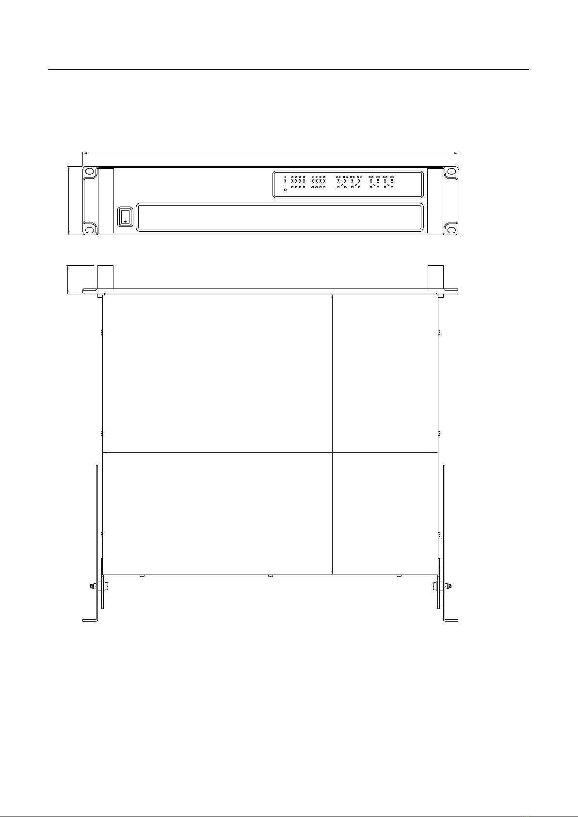
INSTALLATION INSTRUCTIONS
Mechanical Installation
The Di Series Amplifiers are designed to be mounted in a standard 19” rack enclosure.
Where the amplifier is used in a fixed installation, as long as the bottom unit is supported and there
are no gaps between units, it is acceptable to use only the front panel 19” rack holes when fitting it in
a standard rack enclosure. If the amplifier is mounted in a mobile rack it is important that the rear is
supported with a rear rack mounting kit (part number ZA1182). Damage caused by insufficient
support is not covered by the warranty.
431
360
37
482
88

13
To prevent damage to the front panel it is recommended that plastic cups or washers are fitted
underneath the rack mounting bolt heads.
It is possible to mount multiple Di Series amplifiers without ventilation gaps between them but it is
essential that an unobstructed flow of clean air is available from the front of the unit to the rear. It is
important that neither the air intakes on the front of the unit or the exhaust vents at the rear are
covered. Steps must be taken to ensure that hot air does not continually circulate through the
amplifiers from the back of the rack to the front.
The amplifier should never be exposed to rain or moisture during operation or storage. If the unit does
come into contact with moisture, remove the AC power cord immediately and leave it in a dry and
warm location to dry out.
Note that when any equipment is taken from a cold location into a hot humid one, condensation may
occur inside the device. Always allow time for the equipment to attain the same temperature as its
surrounding environment before connecting the AC power cord.
IMPORTANT
It is the responsibility of the user to ensure that dirt, liquids and vapour from theatrical smoke and fog
machines is not ingested by the amplifier. Damage so caused is not covered by the manufacturer’s
warranty.
AC Power Connection
The amplifier utilises a 32A Neutrik PowerConTM type locking AC power connector. Use only an AC
power cord with a correctly terminated PowerConTM type connector to make the connection to the
mains power supply.
The amplifiers are designed to operate on 50/60 Hz AC power. The power supply sections
automatically configure themselves for either 115V or 230V nominal voltage at turn on. The
amplifiers will operate over an extended range of supply voltages (please refer to the technical
specifications).
Note that whilst the amplifier will operate correctly at voltages indicated, the specified output power
will only be achieved when operating with the stated nominal voltages.

14
Introduction and Key Features
Introduction
The EM Acoustics Di Series Advanced Installation Amplifier represents current state-of-the-art
technology in several areas. This product is the result of several years of research, from which many
advances in switched mode power technologies and ever finer detail in signal processing have
stemmed. Taking advantage of the latest advances in analogue to digital conversion technologies,
the unit achieves performance levels among the very best that engineering permits.
Below is a list of key features, followed by some information on the major advanced features of the
product.
Key Features
-Four/Eight channels of sonically pure Class D amplification
-Very high power density - packs eight channels and 20kW into just 2U of rack space
-Packed with robust protection and monitoring systems to keep the show going
-External Breaker Protection (EBP) limits the current draw to prevent breakers opening
-Minimal signal path design
-Class leading sonic performance achieved by the use of state of the art Amplifier technologies
and highly advanced DSP algorithms using Linea Micro Detail (LMD)
-96kHz sampling frequency provides for a nominally flat response beyond 40kHz.
-Simple tamper-proof front panel offers intuitive indication of status
-High speed Ethernet communications supporting DHCP, static-IP and auto-IP and direct
connection to a computer without the need for a router or a switch
-Powerful Drive Module concept, abstraction from device centric to speaker based control
-Innovative Component Presets to allow individual outputs to be used for selected drivers of a
loudspeaker system
-Twelve layers of Parameter Overlays for trouble-free Grouping
-Unique VX limiter providing dynamic control for passive 2-way enclosures
-Unique LIR linear phase crossover shapes giving FIR-like performance without the drawbacks
-Linear phase HF system EQ profiling which provides perfect integration between enclosures
-Innovative excursion control limiter with sliding High Pass Filter; limits only the damaging low
frequencies
-Transducer thermal modelling provides regulation limiters, addressing long term overload
-Overshoot limiter governs amplitude of transient signals retaining average power whilst
constraining peak energy
-Dante audio networking with automatic fallover to Analogue or AES3
-AES3 input

15
Drive Modules
The Di Series processor has a new way of ordering and grouping channels in order to give a more
speaker-based approach to controlling, designing and recalling speaker configurations; these are
called Drive Modules. A Drive Module is the Processing provided by one Input DSP Block, and a number
of Output DSP Blocks, which are associated with one-another by means of routing. For example, if
Input DSP Block B is routed to Outputs 3 and 4, then this is a 2-way Drive Module with Input DSP
Block B forming the ‘Master’ control, and Output DSP Blocks 3 and 4 providing the driver-related
control. Overall, this forms the processing typically for one loudspeaker sub-system. The System
Engineer Drive Module control panel for this sub-system may then be used for control and monitoring
of the associated speaker.
Drive Modules may be included in Module Groups, which use the Parameter Overlay feature in the
Device to achieve trouble-free Grouping in the System Engineer application.
The Presets in the Device are Drive-Module centric, and are used to configure individual Drive
Modules rather than the whole device.
Importantly, Drive Modules move the focus away from the processing device, and onto the
loudspeaker systems.
A Drive Module Preset may be broken apart into Components, allowing any output to be used for any
component within a Drive Module Preset (i.e. any driver in a loudspeaker subsystem).
See Overview of Modules
Overlays
When the Device is used in Modules view in System Engineer, this allows the modules to be grouped
into
Overlay
G
roups
. These groups allow various Input (master) parameters to be adjusted in
all
modules
in that group, whist maintaining independent parameter values across each group. This is
achieved in the device by combining the parameters for all the layers for a given section (Gain Delay,
EQ etc.). When an Overlay parameter is active, the Overlay indicator will become illuminated. The
combined Gain or Delay etc. associated with a given section is shown on the module panel in System
Engineer, within square brackets []under the Delay and Gain for each input channel. The combined
EQ curve is shown in an olive colour. The Input Mute button in System Engineer will flash if an overlay
mute is active. An input overlay mute is indicated on the mute/clip indicator for that channel flashing.
S
ee Overlay Flush
. Note that overlays are not stored in presets or snapshots or carried in settings
files.
LIR Linear Phase Crossover Filtering
The Device also includes a new type of crossover filtering “Linear Impulse Response” (LIR) crossover
filtering, which results in a Linear Phase crossover that has a constant delay regardless of frequency
(unlike other types of crossover which delay different frequencies to a different extent, thus
smearing the arrival time). The LIR crossover can thus be described as having a flat Group Delay
response, and thus entirely free of Group Delay Distortion.
The shape of the LIR crossover filter is quite similar to a 4th order or 24dB/Oct Linkwitz-Riley filter,
and maintains zero phase difference between the adjacent bands across the crossover region to keep
the polar response rock steady.

16
FIR Linear Phase Equalisation
The Input High-Shelf Equalisers use Finite Impulse Response (FIR) filtering to produce Linear Phase
equalisation; that is all frequencies are delayed by the same amount, perfectly preserving the
transient response. This can also be important in applications where different amounts of EQ are
applied to different parts of a speaker cluster, such as to add 'Throw' EQ boost so that parts of cluster
which are throwing further can have HF absorption correction added. If this EQ is not linear phase,
then the zones where the speakers combine may suffer frequency response anomalies.
17
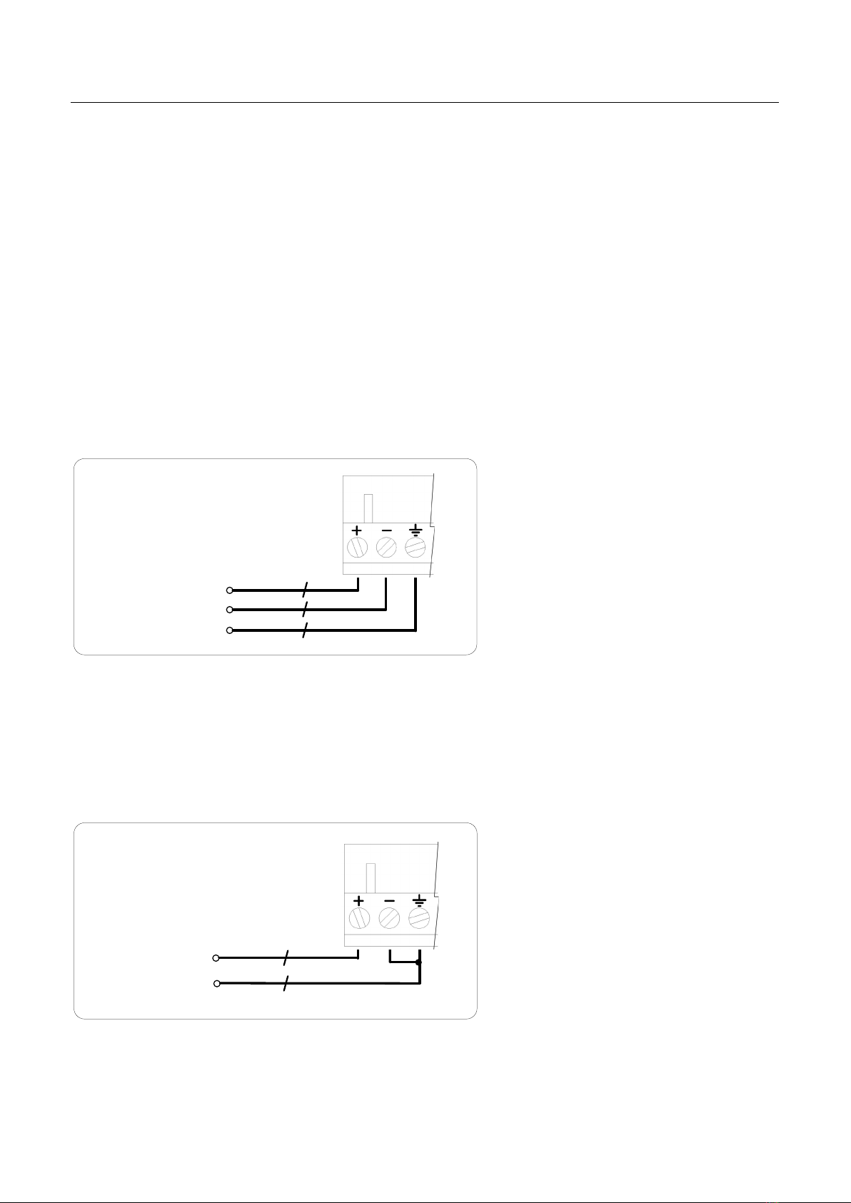
Audio Connections
Input Connections
For each input channel there are 3 pins of a Phoenix connector for analogue inputs.
There is also a 6 pin Phoenix connector for one stream (two channels) of AES3 digital audio. The three
terminals marked ‘In’ should be used as the AES3 input to the device. The ‘Link’ terminals are intended
to feed a buffered version of the input on to another device. The ‘Link’ output will still work even
when power is not applied to the device. Note that only two channels of AES3 digital audio are
available. The Dante option permits more channels of Digital Audio inputs.
The HOT, + or ‘in phase’ connection should be made to the + pin of the Phoenix connector.
The COLD, - or ‘out of phase’ connection should be made to the - pin of the Phoenix connector.
The ‘⏚’ Pin of the input connectors is internally connected to the chassis. The shield of the input
cable should always be connected to the ‘⏚’ Pin of the input connector to ensure that EMC
performance and regulations are met.
Pin 2 HOT +
Pin 3 COLD -
Pin 1 Shield
Balanced Input connection
Using unbalanced connections
Please note that the use of unbalanced connections is not recommended, however when connecting
the amplifier to an unbalanced audio source, the signal conductor should be connected to the ‘+’
terminal. The ‘Cold’ conductor or cable screen should be connected to the ‘-‘ terminal with a short
connection made between the ‘-‘ pin and the ‘⏚’ pin.
HOT +
Shield
Unbalanced Input connection

18
Amplifier Output Connections
On the Di Series amplifiers, all outputs are Bi-Amp; each SpeakonTM connector carries two amplifier
outputs – Channels 1&2, Channels 3&4, Channels 5&6 and Channels 7&8.
Amplifier output connections – 88C and Bi Amp
2+
1-
1+
2-
Speaker1 +
Speaker1 -
Speaker2 +
Speaker2 -
In addition, all the SpeakonTM connectors can also be used if the pair of amplifier channels is being
operated in bridged mode.
Amplifier output connections – Bridge
2+
1-
1+
2-
Speaker +
Speaker -
More than one speaker can be connected to each channel provided the total impedance per channel is
not less than 2 ohms. In bridged mode the minimum total impedance should not be less than 4 ohms.
Load Matching
Each output of the device can be optimised to drive either a low impedance load (e.g. 2, 4 or 8 Ohms),
or a Constant Voltage (C.V.) using the Load parameter in the Output menu. There are several C.V.
settings (25V, 70V and 100V Line) which determine the maximum RMS voltage that the amplifier will
produce. Select the one which is appropriate for the installation. A number of low impedance settings
(depending on the model) are also available. Although it is not critical that this setting matches the
impedance of the connected load, this will maximise the power that is available for the load.

19
Panel Layouts
Power Switch- Applies mains power to the device. If the device has entered Sleep mode, it may be
woken up again either from the System Engineer application, or by switching this switch off, then on
again.
Status Indicators- The “OVERLAY” indicator shows when there are parameters active on a group
layer, which the user cannot access through the front panel of the device (see Overlay Flush). The
“DANTE” indicator shows that a networked digital audio card is installed and routed. The “ONLINE”
indicator has three states:
Off
– the unit is offline and not connected to a computer or network.
Flashing
- the unit is searching for an IP address; if the unit does not find an IP address the unit will
assign itself an IP address automatically and the indicator will stop flashing.
On
- the unit is online and
connected with software. IP settings can be viewed or changed within the <UTILITY> pages.
Input Signal Indicators- A set of indicators show “Sig”, “-20”, “-10” and “Clip (mute)” for each of the
DSP inputs Ato H.The signal present Indicators operate at approximately –40 dBu. The Clip/mute
Indicators warn the user of input overload and operate at 1dB before clip. This indicator also shows a
muted input. The indicators in the input section are sometimes used to show progress of an action (a
clockwise rotating wheel pattern), or confirmation of an action (e.g. an expanding square to confirm
snapshot recall), or an error condition (‘Motorway’ hazard flashing).
Bridge Indicator- This will illuminate when the channel pair is in Bridge mode. The controls for the
left channel of the pair will determine the settings. See Bridge Mode
Amplifier Indicator- This indicates when the amplifier protection systems are reducing the gain to
keep the parameters of the amplifier within specification, or when that the channel is clipping.
Driver Indicator- This indicates a signal 6dB higher than the limiter threshold, or when the threshold
of the excursion limiter has been exceeded, or when the thermal limiter is active. Please note that
because of the long release time of the thermal limiter, this indicator may remain illuminated for
several seconds after signal on that channel is reduced.
Limiter Indicators- The output indicators shows the status of the limiter and output signal level. The
level indicated is that before the limiter, referenced to the limiter threshold. The <SIG> indicator
shows when a signal is present on the output. The second indicator <-6dB> shows that the signal has
reached 6dB below the limiter threshold. The third <LIMIT> indicator indicates that the threshold of
that output channel has been reached. The indicators in the output section are sometimes used to
show progress of an action (by illuminating progressively more indicators), or confirmation of an
action (e.g. illuminating a number of indicators equalling the number of a Snapshot being recalled).

20
Ethernet Communications Port: The device may be controlled entirely from another controller, typically a Personal
Computer, running an application that is compliant with the ObCom standard such as System Engineer. Connection will
normally be made to the controller via this Ethernet port connector. This port is also used for updating the firmware in
the unit.
Auxiliary Port A: The default operation is X = Mute when connected to
⏚
(Ground / 0V) , Y = Sleep when connected to
Ground (0v).
Networked Audio Ports:The device has the option for DanteTM networked audio ports; if none are required a blanking
plate will be fitted.
Power Inlet:The unit should be connected to a suitable mains electricity supply using an earthed Powercon connection
power lead. The device has a switch mode power supply that is capable of operating with a nominal mains voltage of
100V to 230V, 50/60Hz without re-configuration.
NOTE: The device must be earthed to a suitable power earth; failure to do so may affect performance and/or operation
and will invalidate warranty and could be potentially hazardous.
Analogue Audio Input Connectors: All audio connections are fully balanced.
Relay A output: This isolated relay output may be used to indicate abnormal conditions to external monitoring
apparatus. The default operation is to indicate a Fault Incident. See Fault Relay
AES3 Audio Input Connector:For inputting Digital Audio signals. The Input is fully balanced. The Link connector allows
a buffered AES3 signal to be passed on to another device. The connection ‘heals over’ when the unit is not powered up.
Aux Port B Connector: Logic inputs. The default operation is to recall one of the Snapshots 1 thru 5 by applying a
Ground (0v) to one of these pins, either momentarily or permanently.
Loudspeaker Connectors: The amplifier SpeakonTM outputs. Connect the first loudspeaker to the 1+ and 1- terminals
and the second loudspeaker to the 2+ and 2- terminals. For Bridged mode, use terminals 1+ and 2+.
Aux Port C Connector
Relay B output: This isolated relay output may be used to indicate abnormal conditions to external monitoring
apparatus. The default operation is to indicate a Check Incident. See Check Relay
5V,
⏚
(Ground / 0V):This power output may be used for energising external indicators etc from either the Fault relay
or Check relay for example. This output is not capable of supplying more than 100mA of current.
Hb: The Heartbeat output. This outputs a 1Hz square wave all the time the unit is operating correctly.
Serial communications Connectors: The device may be controlled via this ‘third party interface’ using either RS232 or
RS485 protocol at a rate of 38.4k Baud. Only one of these may be used at a time. Please refer to the “Tipi Interface
Specification” document for details on how to use it.
This manual suits for next models
2
Table of contents
Other EM Acoustics Amplifier manuals


Popular Amplifier manuals by other brands

Audio Analogue
Audio Analogue PRIMO owner's manual

Pioneer
Pioneer SA-V210 Service manual

Shinybow USA
Shinybow USA SB-565 U2 Series instruction manual

Mojotone
Mojotone FX LOOP v.2 installation manual

Marshall Amplification
Marshall Amplification Valvestate VS15 Handbook

Planet Audio
Planet Audio AC3000.1D user manual


