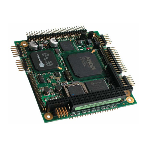
EMAC PCM-9340F-0CA1 User manual

i
PCM-9340
ISA STPC Elite 133 SBC with
CPU/32MB SDRAM/VGA/LCD/
LAN/DOC/PC104
Users Manual

PCM-9340 User’s Manual ii
Copyright
This document is copyrighted, ©2002, by EMAC, Inc. All rights
reserved. The original manufacturer reserves the right to make
improvements to the productsdescribed in this manual at any time with-
out notice.
No part of this manual may be reproduced, copied, translated or transmit-
ted in any form or by any means without the prior written permission of
the original manufacturer. Information provided in this manual is
intended to be accurate and reliable. However, the original manufacturer
assumes no responsibility for its use, nor for any infringements upon the
rights of third parties that may result from such use.
Acknowledgements
Award is a trademark of Award Software International, Inc.
VIA is a trademark of VIA Technologies, Inc.
IBM, PC/AT, PS/2 and VGA are trademarks of International Business
Machines Corporation.
Intel and Pentium are trademarks of Intel Corporation.
Microsoft Windows® is a registered trademark of Microsoft Corp.
RTL is a trademark of Realtek Semi-Conductor Co., Ltd.
ESS is a trademark of ESS Technology, Inc.
UMC is a trademark of United Microelectronics Corporation.
SMI is a trademark of Silicon Motion, Inc.
Creative is a trademark of Creative Technology LTD.
All other product names or trademarks are properties of their respective
owners.
For more information on this and other EMAC products, please visit
our website at: http://www.emacinc.com
For technical support and service, please visit our support website at:
http://www.emacinc.com/technical_support.htm
This manual is for the PCM-9340 3.5" Biscuit SBC.

iii
Packing List
Before you begin installing your card, please make sure that the following
materials have been shipped:
• 1 PCM-9340 all-in-one single board computer
• 1 startup manual
• 1 CD-ROM or disk for utilities, drivers, and manual
(in PDF format)
• 1 3.5" IDE flat cable P/N: (1701440504)
• 1 keyboard/mouse cable P/N: (1700060202)
• 1 secondary serial port cable P/N: (1701140201)
• 1 parallel cable P/N: (1700260250)
• 1 floppy cable P/N: (1701340603)
• 1 COM3/COM4 cable P/N: (1701200220)
• 1 Mini Jumper package (10 PCS) P/N: (9689000002)
If any of these items are missing or damaged, contact your distributor or
sales representative immediately.
The PCM-9340 Series Model Comparison Table
CPU 32MB
Memory
VGA/LCD Ethernet
PCM-9340F-0CA1 vv v v
PCM-9340V-0CA1 vv v
PCM-9340N-0CA1 vv v

PCM-9340 User’s Manual iv

Table of Contents
v
Contents
Chapter 1 General Information ........................................1
1.1 Introduction ....................................................................... 2
1.2 Features ............................................................................. 3
1.3 Specifications .................................................................... 4
1.3.1 Standard SBC functions.................................................. 4
1.3.2 Flat Panel/VGA Interface ............................................... 4
1.3.3 Ethernet Interface (PCM-9340F and PCM-9340N)........ 5
1.3.4 Audio Interface (optional) .............................................. 5
1.3.5 Mechanical and Environmental ...................................... 5
1.3.6 Solid state disk ................................................................ 5
1.4 Board layout: dimensions.................................................. 6
Figure 1.1:Board layout: dimensions.............................. 6
Chapter 2 Connecting Peripherals ...................................7
2.1 Jumpers.............................................................................. 8
2.1.1 Jumper Locations............................................................ 8
Figure 2.1:Jumper Locations .......................................... 8
2.1.2 Jumper Functions............................................................ 9
2.1.3 Setting Jumpers............................................................... 9
2.2 COM2 Select (JP2).......................................................... 10
2.3 Watchdog Timer Action (JP3) ........................................ 10
2.4 DOC© 2000 Address Setting (JP4) ................................ 11
2.5 Clear CMOS (JP5) .......................................................... 12
2.6 Audio Amp Power Select (JP7) ...................................... 12
2.7 Connectors....................................................................... 13
2.7.1 Connector Locations ..................................................... 13
Figure 2.2:Connector Locations ................................... 13
2.7.2 Connector Functions ..................................................... 14
2.8 Making Connections ....................................................... 15
2.9 CPU Fan power supply connector (CN1) ....................... 15
2.10 Serial ports (CN2, CN3, CN4) ........................................ 15
2.10.1 COM3/COM4 RS-232 port (CN2) ............................... 15
2.10.2 COM2 RS-232/422/485 selection (CN3) ..................... 16
2.10.3 COM1 RS-232 port (CN4) ........................................... 16
2.10.4 Share IRQ ..................................................................... 16
2.11 PC/104 connectors (CN5) .............................................. 16
2.12 Ethernet Connections (CN6, LED1, LED2).................... 16
2.12.1 100Base-T RJ-45 connector (CN6) .............................. 17
2.12.2 Network boot ................................................................ 17
2.12.3 Ethernet LED and HDD/power LEDs .......................... 17
2.13 Keyboard and PS/2 mouse connector (CN7) .................. 17

vi
2.14 IR connector (CN8)......................................................... 18
2.15 Enhanced IDE HDD Connector (CN9)........................... 18
2.16 VGA interface connections (CN10, CN15, CN19)......... 18
2.16.1 CRT display connector (CN10) .................................... 18
2.16.2 Extension flat panel connector (CN15) ........................ 19
2.16.3 Flat panel display connector (CN19) ............................ 19
2.17 Audio interfaces (CN11, CN17) (optional)..................... 19
2.17.1 Audio connector (CN11) .............................................. 19
2.17.2 CD audio input connector (CN17)................................ 19
2.17.3 Audio power source setting (JP7)................................. 19
2.18 ATX power (CN13, CN16, CN22) ................................. 21
Figure 2.3:Wiring for ATX feature power.................... 21
2.18.1 ATX feature connector (CN13) .................................... 21
2.18.2 Board Main Power (CN16)........................................... 21
2.18.3 ATX soft power switch (CN22).................................... 21
2.19 FDD connector (CN14)................................................... 22
2.20 Parallel port connector (CN18) ....................................... 22
2.21 General Purpose Input Output (CN20)............................ 22
Chapter 3 Award BIOS Setup.........................................23
3.1 System test and initialization........................................... 24
3.1.1 System configuration verification................................. 24
3.2 Award BIOS setup .......................................................... 25
3.2.1 Entering setup .............................................................. 25
Figure 3.1:BIOS setup program initial screen .............. 25
3.2.2 Standard CMOS Features setup.................................... 26
Figure 3.2:CMOS Features setup.................................. 26
3.2.3 Advanced BIOS Features setup .................................... 27
Figure 3.3:Advanced BIOS Features setup................... 27
3.2.4 Advanced Chipset Features setup ................................. 28
Figure 3.4:Advanced Chipset Features setup ............... 28
3.2.5 Integrated Peripherals ................................................... 29
Figure 3.5:Integrated Peripherals.................................. 29
3.2.6 Power Management Setup ............................................ 30
Figure 3.6:Power Management Setup........................... 30
3.2.7 PnP/PCI Configurations................................................ 31
Figure 3.7:PnP/PCI Configurations .............................. 31
3.2.8 Load Optimized Defaults.............................................. 32
Figure 3.8:Load BIOS defaults screen.......................... 32
3.2.9 Set Password ................................................................. 32
Figure 3.9:Set Password ............................................... 34
3.2.10 Save & Exit Setup......................................................... 35
Figure 3.10:Save and Exit Setup................................... 35
3.2.11 Exit Without Saving...................................................... 36
Figure 3.11:Exit without Saving................................... 36

Table of Contents
vii
Chapter 4 SVGA Setup....................................................37
4.1 Introduction ..................................................................... 38
4.1.1 Chipset .......................................................................... 38
4.1.2 Display memory............................................................ 38
4.2 Installation of the SVGA Driver ..................................... 38
4.2.1 Installation for Windows 95 ......................................... 39
4.2.2 Installation for Windows 98 ......................................... 44
4.2.3 Installation for Windows NT ........................................ 49
4.3 Further Information ......................................................... 54
Chapter 5 PCI Bus Ethernet Interface...........................55
5.1 Introduction ..................................................................... 56
5.2 Ethernet Driver Installation............................................. 56
5.2.1 Installation for Windows 95 ......................................... 57
5.2.2 Installation for Windows 98 ......................................... 62
5.2.3 Installation for Windows NT ........................................ 69
5.3 Further information ......................................................... 71
Chapter 6 Audio Setup.....................................................73
6.1 Introduction ..................................................................... 74
6.2 Audio Driver Installation ................................................ 74
6.2.1 Installation for Windows 95/98/NT.............................. 75
Appendix A Programming the Watchdog Timer .............77
A.1 Supported Input Timing Modes ...................................... 78
Appendix B Installing PC/104 Modules ............................81
B.1 Installing PC/104 Modules.............................................. 82
Figure B.1:PC/104 module mounting diagram............. 83
Figure B.2:PC/104 module dimensions (mm) (±0.1) ... 84
Appendix C Pin Assignments .............................................85
C.1 CPU fan power connector (CN1).................................... 86
C.2 COM 3, COM 4 connector (CN2)................................... 86
C.3 COM 2 connector (CN3)................................................. 87
C.4 COM 1 RS-232 connector (CN4).................................... 87
C.5 PC/104 Connector (CN5) ................................................ 88
C.6 Ethernet 10/100Base-T Connector (CN6)....................... 90
C.7 Keyboard and PS/2 Mouse Connector (CN7) ................. 90
C.8 IR Connector (CN8) ........................................................ 91
C.9 IDE Hard Drive Connector (CN9) .................................. 92
C.10 CRT Display Connector (CN10)..................................... 93
C.11 Audio Connector (optional) (CN11) ............................... 93
C.12 LCD Inverter Backlight Connector (CN12).................... 94
C.13 ATX Power Feature Connector (CN13).......................... 94
C.14 Floppy Disk Drive Connector (CN14) ............................ 95

viii
C.15 Extended Flat Panel Display Connector (CN15.............. 96
C.16 Main Power Connector (CN16) ...................................... 96
C.17 CD audio connector (CN17) ........................................... 96
C.18 Parallel Port Connector (CN18) ...................................... 97
C.19 Flat Panel Connector (CN19).......................................... 98
C.20 General Purpose Input Output (CN20)............................ 99
C.21 Auxiliary power connector (CN21)................................. 99
C.22 ATX Power Button (CN22) ............................................ 99
C.23 Reset Button Connector (SW1)..................................... 100
Appendix D System Assignments .....................................101
D.1 System I/O Ports............................................................ 102
D.2 DMA channel assignments............................................ 103
D.3 Interrupt assignments .................................................... 104
D.4 1st MB memory map..................................................... 105
D.5 DMA channel assignments............................................ 105
D.6 Interrupt assignments .................................................... 106
Appendix E Mechanical Drawings...................................107
E.1 Mechanical Drawings.................................................... 108

1 Chapter 1 General Information
Chapter 1 General Information
1
General Information
This chapter gives background
information on the PCM-9340.
Sections include:
• Introduction
• Features
• Specifications
• Board layout and dimensions
CHAPTER

PCM-9340 User’s Manual 2
Chapter 1 Introduction
1.1 Introduction
The PCM-9340 is the ultimate cost-effective solution for limited-space
applications. It offers all the functions of an AT-compatible industrial
computer on a single board. The PCM-9340 comes with an embedded
high-performance STPC Elite 133 processor and 32MB SDRAM on
board. For maximum performance, the PCM-9340 also supports one
optional SODIMM socket that can accept up to 64 MB memory.
On-board features include an Ethernet interface, a socket for DOC®
2000, Enhanced IDE interface, one parallel port, four serial ports (three
RS-232s, and one RS-232/422/485) with DB-9 connectors, and a mini-
DIN PS/2 keyboard/mouse interface, and an optional audio function. An
SVGA/LCD display controller (LCD, and CRT displays) allows LCD
screen resolutions up to 1024 x 768 @ 64K colors and CRT resolutions
up to 1280 x 1024 @ 256 colors.
The PCM-9340 complies with the “Green Function” standard and sup-
ports three types of power saving features: Normal, Doze and Sleep
modes.
The display type configuration is done through software. A single Flash
chip holds the system BIOS and the VGA BIOS. This minimizes the
number of chips and eases configuration. You can change the display
BIOS simply by programming the Flash chip.
If you need any additional functions, the PCM-9340 has a PC/104 con-
nector for future upgrades.

3 Chapter 1 General Information
1.2 Features
• On-board Low power STMicroelectronics STPC Elite 133 processor
(fanless)
• On-board 32 MB SDRAM
• On-board VGA/LCD display controller and supports DSTN/TFT LCD
• 62-level watchdog timer, jumperless on-line setup supported
• Supports wake-up on LAN, ring-on by Modem
• SSD supports DiskOnChip® 2000
• Supports CMOS data backup functions
• PC/104 connector supports face-up installation
• Optional audio function

PCM-9340 User’s Manual 4
1.3 Specifications
1.3.1 Standard SBC functions
• CPU: Embedded STMicroelectronics STPC Elite 133 MHz processor
(provides fanless operation)
• BIOS: 2 Mbit Flash BIOS,
-Supports Plug & Play, APM
-Supports Ethernet Boot ROM
-Supports boot from CD-ROM
-Supports boot from LS-120 ZIP™ Drive
-Optional Customer icon can be supplied
• Chipset: STPC Elite 133
• System memory: Onboard 32MB SDRAM,
and one optional SDRAM SODIMM max. 64MB socket
• PCI IDE interface: One Enhanced IDE interface. Supports 2 IDE
devices PIO mode 3,4 with bus mastering up to 14 MB/sec.
• Floppy disk drive interface: Supports up to two FDDs (360 KB/1.2
MB/720 KB/1.44 MB/2.88 MB)
• Parallel port: One parallel port, supports EPP/ECP
• IR port: One 115 Kbps IrDA compliant serial infrared
• Serial ports: 4 serial ports:: COMs1,3,4: RS-232; COM2:
RS-232/422/485; COM2 RS-485 supports Autoflowcontrol
• Watchdog timer: 62-level timer interval, setup by software or jumper-
less selection, generates system reset or IRQ11.
1.3.2 Flat Panel/VGA Interface
(PCM-9340F and PCM-9340V)
•Chipset: SMI LynxEM+ 712
•Display memory: 2 MB on the chip
•Display type: Simultaneous support for CRT and 36-bit TFT LCD
display (supports 3.3 V LCD) Supports 3, 9,12,18, 24, 36-bit TFT and
16 or 24-bit DSTN Panel
•CRT display modes:
1280 x 1024@16bpp (60Hz)
1024 x 768@16bpp (85Hz)
800 x 600 @24bpp(85Hz)

5 Chapter 1 General Information
•Panel display modes:
1280 x 1024@16bpp (60Hz)
1024 x 768@16bpp (60Hz)
800 x 600 @24bpp(60Hz)
1.3.3 Ethernet Interface (PCM-9340F and PCM-9340N)
•Chipset: RTL 8139C
•Ethernet interface: PCI 10/100 Mbps Ethernet. IEEE 802.3 u proto-
col compatible
•Connection: On-board RJ-45 connector
•Wake on LAN (via ATX power supply)
• I/O address switchless setting
• Built-in boot ROM
1.3.4 Audio Interface (optional)
•Chipset: Avance Logic ALS4000
• PCI Interface, Mic in, Line in, CD Audio in, Line out, speaker out
1.3.5 Mechanical and Environmental
•Dimensions (L x W): 145 mm x 102 mm (5.9" x 4.2")
•Power supply voltage: +5 V (4.75 V ~ 5.25 V)
•Power requirements: Maximum: 5.0 V @ 2 A
Typical: +5.0 V @ 1.62 A
•Operating temperature: 0 ~ 60° C (32 ~ 140° F)
• Operating humidity: 0% ~ 90% Relative Humidity, non-condensing
•Weight: 0.23 Kg (0.5 lbs)
• Size: 185 mm x 122 mm
1.3.6 Solid state disk
• Provides support for one DOC® 2000.

PCM-9340 User’s Manual 6
1.4 Board layout: dimensions
Figure 1.1: Board layout: dimensions

7 Chapter 2 Connecting Peripherals
Chapter 2 Connecting Peripherals
2
Connecting Peripherals
This chapter tells how to connect
peripherals, switches, and indicators to the
PCM-9340 board. It also covers jumper
settings. You can access most of the con-
nectors from the top of the board while it
is installed in the chassis. If you have a
number of cards installed, or your chassis
is very tight, you may need to partially
remove the card to make all the connec-
tions.
CHAPTER

PCM-9340 User’s Manual 8
Chapter 2 Installation
2.1 Jumpers
The PCM-9340 has a number of jumpers that allow you to configure your
system to suit your application.
2.1.1 Jumper Locations
Figure 2.1: Jumper Locations

9 Chapter 2 Connecting Peripherals
2.1.2 Jumper Functions
2.1.3 Setting Jumpers
You may configure your card to match the needs of your application by
setting jumpers. A jumper is a metal bridge used to close an electric cir-
cuit. It consists of two metal pins and a small metal clip (often protected
by a plastic cover) that slides over the pins to connect them. To “close” a
jumper, you connect the pins with the clip. To “open” a jumper, you
remove the clip. Sometimes a jumper will have three pins, labeled 1, 2
and 3. In this case you would connect either pins 1 and 2, or 2 and 3.
The jumper settings are schematically depicted in this manual as follows:.
A pair of needle-nose pliers may be helpful when working with jumpers.
If you have any doubts about the best hardware configuration for your
application, contact your local distributor or sales representative before
you make any changes.
Table 2.1: Jumper Functions
Label Function
JP2 COM2 selector
JP3 Watchdog timer action
JP4 DOC® 2000 address setting
JP5 Clear CMOS
JP7 Audio power selector
open closed closed 2-3
open closed 2-3 closed

PCM-9340 User’s Manual 10
2.2 COM2 Select (JP2)
2.3 Watchdog Timer Action (JP3)
An on-board watchdog timer reduces the chance of disruptions which
EMP (electro-magnetic pulse) interference can cause. This is an invalu-
able protective device for standalone or unmanned applications. Setup
involves one jumper setting and running the control software (refer to
Appendix A).
When the watchdog timer activates (CPU processing has come to a halt),
it can either reset the system or generate an interrupt on IRQ11. This
choice for watchdog timer action is set via JP3 as shown below:
Table 2.2: JP2: COM2 RS-232/422/485 Select
Pins Function
1-2* COM2/RS-232*
3-4 COM2/RS-422
5-6 COM2/RS-485
* default setting
RS-232* RS-422 RS-485
Table 2.3: JP3: Watchdog Timer
Pins Function
1-2* Reset
2-3 IRQ 11
* default setting
reset* IRQ 11
246
135
246
135
246
135

11 Chapter 2 Connecting Peripherals
2.4 DOC© 2000 Address Setting (JP4)
Table 2.4: JP4: DOC® 2000 address setting
Pins Address
1-2 3-4 5-6
closed closed open CC000 ~ CDFFF
*closed open closed D0000 ~ D1FFF
closed open open D4000~ D5FFF
open closed closed D8000 ~ D9FFF
open closed open DC000 ~ DDFFF
open open open OFF
*default setting
CC000 ~ CDFFF D0000 ~ D1FFF* D4000~ D5FFF
D8000 ~ D9FFF DC000 ~ DDFFF OFF
246
135
246
135

PCM-9340 User’s Manual 12
2.5 Clear CMOS (JP5)
2.6 Audio Amp Power Select (JP7)
Warning! To avoid damaging the computer, always turn
off the power supply before clearing the
CMOS. Before turning the power supply back
on, return the jumper to “3.0 V Battery On.”
Table 2.5: JP5: Clear CMOS
Pins Function
1-2 clear CMOS
2-3* 3.0 V battery on
* default setting
clear CMOS 3.0 V battery on*
Table 2.6: JP7: Audio amplifier power select
Pins Function
1-2* +5V (main power)
2-3 Regulated +5V
* default setting
+5V (main power)* Regulated +5V
This manual suits for next models
2
Table of contents
Other EMAC Single Board Computer manuals
Popular Single Board Computer manuals by other brands
Motorola
Motorola MVME177 Installation and use manual

ICP Electronics
ICP Electronics ROCKY-512 manual
Avalue Technology
Avalue Technology ECM-SKLU-B1 user manual
Seco
Seco SBC-C41-pITX user manual
Connect Tech
Connect Tech COM Express Type 7+ user guide
IEI Technology
IEI Technology WAFER-EHL-J6412 Quick installation guide

