EMAK Emal EP 120 User manual

EP 120
Manuale d’istruzioni
User instruction book
Manuel d’instructions
Betriebsanleitungen
Manual de instrucciones
Handleiding
Manual de instruções
∂Á¯ÂÈÚ›‰ÈÔ Ô‰ËÁÈÒÓ
Talimat kitapçığı
Návod k použití
Руководство по эксплуатации
Instrukcja
Használati kézikönyv
Návod na použitie
C
B
EP 120EF
EMAK s.p.a. - Member of the YAMA group
42011 BAGNOLO IN PIANO (REGGIO EMILIA) ITALY
TEL. 0522956611 - FAX0522951555
D
I
GB
F
D
E
NL
P
GR
TR
CZ
RUS
PL
H
SK
La casa costruttrice si riserva la possibilità di variare caratteristiche e dati del presente
manuale in qualunque momento e senza preavviso.
The manufacturer reserves the right to change the specifications and data indicated in
this manual at any time and without notice.
Le fabricant se réserve la possibilité de modifier les caractéristiques et les données du
présent manuel à tout moment et sans préavis.
Der Hersteller behält sich die Möglichkeit vor, die im vorliegenden Handbuch genannten
Eigenschaften und Daten jederzeit und ohne Vorankündigung zu ändern.
El fabricante se reserva el derecho a modificar las características y los datos de los
manuales en cualquier momento y sin aviso previo.
De fabrikant behoudt zich het recht voor om de kenmerken en gegevens in deze hand-
leiding te allen tijde en zonder voorafgaande kennisgeving te wijzigen.
O fabricante reserva-se o direito de alterar as características e os dados do presente
manual a qualquer momento e sem aviso prévio.
√ ηٷÛ΢·ÛÙ‹˜ ‰È·ÙËÚ› ÙÔ ‰Èη›ˆÌ· Ó· ÂÈʤÚÂÈ ·ÏÏ·Á¤˜ ·Ó¿ ¿Û· ÛÙÈÁÌ‹ ÛÙ·
¯·Ú·ÎÙËÚÈÛÙÈο Î·È ÛÙ· ÛÙÔȯ›· ÙÔ˘ ·ÚfiÓÙÔ˜ ÂÁ¯ÂÈÚȉ›Ô˘ ¯ˆÚ›˜ η̛·
ÚÔÂȉÔÔ›ËÛË.
Üretici firma, bu kitapta yer alan teknik bilgileri ve verileri önceden uyarıda
bulunmaksızın herhangi bir anda değiştirme hakkını saklı tutar.
Výrobce si kdykoli vyhrazuje právo na změnu vlastností a údajů uvedených v tomto
návodu bez předběžného upozornění.
Фирма-изготовитель оставляет за собой право вносить изменения в приведенные
в настоящем руководстве характеристики и данные в любой момент и без
предварительного оповещения.
Producent zastrzega sobie możliwość wprowadzania zmian charakterystyk i danych
zawartych w niniejszym podręczniku w dowolnym czasie i bez uprzedzenia.
A gyártó fenntartja a lehetőséget arra, hogy a jelen kézikönyv jellemzőit és adatait bár-
mikor külön értesítés nélkül megváltoztassa.
Výrobca si vyhradzuje právo pozmeniť technické vlastnosti a údaje v tomto návode bez
predchádzajúceho upozornenia.
E
A
I
GB
F
D
E
NL
P
GR
TR
CZ
RUS
PL
H
SK

QUESTO PRODOTTO È CONFORME ALLA DIRETTIVA EUROPEA SULLA
SICUREZZA DELLE MACCHINE
PESO A SECCO (Kg) (SENZA BARRA E CATENA)................................................
PASSO CATENA ....................................................................................................
SPESSORE CATENA (mm) ....................................................................................
LUNGHEZZA BARRA (cm).....................................................................................
No. DENTI DEL PIGNONE .....................................................................................
CAPACITÀ SERBATOIO OLIO (cm3).......................................................................
THIS PRODUCT IS IN CONFORMITY WITH THE EUROPEAN DIRECTIVE ON
THE SAFETY OF MACHINERY
DRY WEIGHT (WITHOUT BAR AND CHAIN) .........................................................
CHAIN PITCH ........................................................................................................
CHAIN GAUGE ......................................................................................................
BAR LENGTH.........................................................................................................
No. SPROCKET TEETH .........................................................................................
OIL TANK CAPACITY .............................................................................................
CET ARTICLE EST CONFORME À LA DIRECTIVE EUROPÉENNE SUR LA
SÉCURITÉ DE LA MACHINE
POIDS À SEC (SANS BARRE NI CHAÎNE).............................................................
PAS DE LA CHAÎNE...............................................................................................
ÉPAISSEUR CHAÎNE .............................................................................................
LONGUEUR BARRE ..............................................................................................
Nbre DENTS DU PIGNON .....................................................................................
CAPACITÉ DU RÉSERVOIR À HUILE ....................................................................
DIESES PRODUKT IST KONFORM MIT DER EUROPÄISCHEN RICHTLINIE
ÜBER DIE SICHERHEIT VON MASCHINEN
TROCKENGEWICHT (OHNE SCHIENE UND KETTE) ...........................................
KETTENTEILUNG ..................................................................................................
KETTENSTÄRKE....................................................................................................
SCHIENENLÄNGE .................................................................................................
ANZAHL DER RITZELZÄHNE................................................................................
ÖLTANKINHALT .....................................................................................................
ESTE PRODUCTO CUMPLE LA DIRECTIVA EUROPEA SOBRE SEGURIDAD
DE LAS MÁQUINAS.
PESO SIN COMBUSTIBLE, ESPADA NI CADENA ................................................
PASO CADENA......................................................................................................
ESPESOR CADENA...............................................................................................
LONGITUD ESPADA ..............................................................................................
N° DIENTES PIÑÓN...............................................................................................
CAPACIDAD DEPÓSITO ACEITE...........................................................................
DIT PRODUCT VOLDOET AAN DE EUROPESE RICHTLIJN BETREFFENDE
DE MACHINEVEILIGHEID
DROOGGEWICHT (ZONDER ZAAGBLAD EN KETTING) ......................................
KETTINGSTEEK.....................................................................................................
KETTINGDIKTE......................................................................................................
LENGTE ZAAGBLAD .............................................................................................
AANTAL TANDEN VAN DE PIGNON ......................................................................
INHOUD OLIETANK ...............................................................................................
ESTE PRODUTO ESTÁ EM CONFORMIDADE COM A DIRECTIVA
EUROPEIA SOBRE SEGURANÇA DA MÁQUINA
PESO A SECO (SEM LÂMINA E CORRENTE).......................................................
PASSO DA CORRENTE .........................................................................................
ESPESSURA DA CORRENTE................................................................................
COMPRIMENTO DA LÂMINA................................................................................
N.º DENTES DO PINHÃO ......................................................................................
CAPACIDADE DO DEPÓSITO DE ÓLEO ...............................................................
0.75
3/8’’
1.1
25
6
184
0.75
3/8’’
1.1
25
6
184
0.75
3/8’’
1.1
25
6
184
0.75
3/8’’
1.1
25
6
184
0.75
3/8’’
1.1
25
6
184
0.75
3/8’’
1.1
25
6
184
0.75
3/8’’
1.1
25
6
184
I
GB
F
D
E
NL
P
DATI TECNICI
TECHNICAL
SPECIFICATIONS
DONNÈES
TECHNIQUES
TECHNISCHE
DATEN
DATOS
TÉCNICOS
TECHNISCHE
GEGEVENS
DADOS
TÉCNICOS

Δ√ ¶ƒ√´√¡ ™Àªª√ƒº√ÀΔ∞π ª∂ Δ∏¡ ∂Àƒø¶∞´∫∏ √¢∏°π∞ ™Ã∂Δπ∫∞ ª∂
Δ∏¡ ∞™º∞§∂π∞ Δø¡ ª∏Ã∞¡ø¡
μ∞ƒ√™ ™øª∞Δ√™ (Ãøƒπ™ ª¶∞ƒ∞ ∫∞π ∞§À™π¢∞) ..............................................
μ∞ƒ√™ ∞§À™π¢∞™ .................................................................................................
¶∞Ã√™ ∞§À™π¢∞™.................................................................................................
ª∏∫√™ ª¶∞ƒ∞™...................................................................................................
∞ÚÈı. ¢√¡Δπø¡ ¶π¡π√¡.........................................................................................
Ãøƒ∏Δπ∫√Δ∏Δ∞ ¢√Ã∂π√À §∞¢π√À ....................................................................
BU ÜRÜN, MAKİNE GÜVENLİĞİ İLE İLGİLİ AVRUPA DİREKTİFLERİNE
UYGUNLUK TAŞIMAKTADIR
NET AĞIRLIK (UÇSUZ VE ZİNCİRSİZ).................................................................
ZİNCİR ÇEVRESİ ..................................................................................................
ZİNCİR ÖLÇÜSÜ...................................................................................................
UÇ UZUNLUĞU.....................................................................................................
PİNYON DİŞLİ SAYISI...........................................................................................
YAĞ TANKI KAPASİTESİ.......................................................................................
TENTO VýROBEK JE V SOULADU SE SMĚRNICÍ PRO BEZPEČNOST STROJŮ
VÁHA ZA SUCHA (BEZ LIŠTY A ŘETĚZU) ............................................................
DĚLENÍ ŘETĚZU....................................................................................................
TLOUŠŤKA ŘETĚZU..............................................................................................
DÉLKA LIŠTY.........................................................................................................
POČ. ZUBŮ ŘETĚZKY...........................................................................................
KAPACITA OLEJOVÉ NÁDRŽKY............................................................................
ДАННОЕ ИЗДЕЛИЕ СООТВЕТСТВУЕТ ЕВРОПЕЙСКОЙ ДИРЕКТИВЕ О
БЕЗОПАСНОСТИ ОБОРУДОВАНИЯ
ЧИСТЫЙ ВЕС (БЕЗ ШИНЫ И ЦЕПИ) .................................................................
ШАГ ЦЕПИ ............................................................................................................
ТОЛЩИНА ЦЕПИ..................................................................................................
ДЛИНА ШИНЫ......................................................................................................
ЧИСЛО ЗУБЬЕВ ЗУБЧАТОГО КОЛЕСА..............................................................
ЕМКОСТЬ МАСЛЯНОГО БАКА ...........................................................................
PRODUKT JEST ZGODNY Z DYREKTYWĄUNIJNĄO BEZPIECZEŃSTWIE MASZYN
CIĘŻAR “NA SUCHO” (BEZ PROWADNICY I ŁAŃCUCHA) ..................................
SKOK ŁAŃCUCHA.................................................................................................
GRUBOŚĆ ŁAŃCUCHA ........................................................................................
DŁUGOŚĆ PROWADNICY ....................................................................................
Il. ZĘBÓW ZĘBNIKA ..............................................................................................
POJEMNOŚĆ ZBIORNIKA OLEJU ........................................................................
A TERMÉK MEGFELEL A GÉPEK BIZTONSÁGÁRÓL SZÓLÓ EURÓPAI IRÁNYELVNEK
SZÁRAZ SÚLY (RÚD ÉS LÁNC NÉLKÜL)..............................................................
LÁNC LÉPTÉK .......................................................................................................
LÁNCVASTAGSÁG.................................................................................................
RÚD HOSSZ ..........................................................................................................
FOGASKERÉK FOGAINAK SZÁMA.......................................................................
OLAJTARTÁLY ŰRTARTALMA ...............................................................................
TENTO VÝROBOK VYHOVUJE EURÓPSKEJ
SMERNICI O BEZPEČNOSTI STROJOV
HMOTNOSŤ BEZ PALIVA (BEZ LIŠTY A REŤAZE) ................................................
ROZCHOD ZUBOV REŤAZE..................................................................................
HRÚBKA REŤAZE..................................................................................................
DĹŽKA LIŠTY.........................................................................................................
POČET ZUBOV OZUBENIA ...................................................................................
OBJEM NÁDRŽE OLEJA .......................................................................................
0.75
3/8’’
1.1
25
6
184
0.75
3/8’’
1.1
25
6
184
0.75
3/8’’
1.1
25
6
184
0.75
3/8’’
1.1
25
6
184
0.75
3/8’’
1.1
25
6
184
0.75
3/8’’
1.1
25
6
184
0.75
3/8’’
1.1
25
6
184
GR
TR
CZ
RUS
PL
H
SK
Δ∂áπ∫∞
Ã∞ƒ∞∫Δ∏ƒπ™Δπ∫∞
TECHNICKÉ
ÚDAJE TEKNİK
BİLGİLER
ТЕХНИЧЕСКИЕ
ДАННЫЕ
DANE
TECHNICZNE
MŰSZAKI
ADATOK
TECHICKÉ
ÚDAJE

3
I
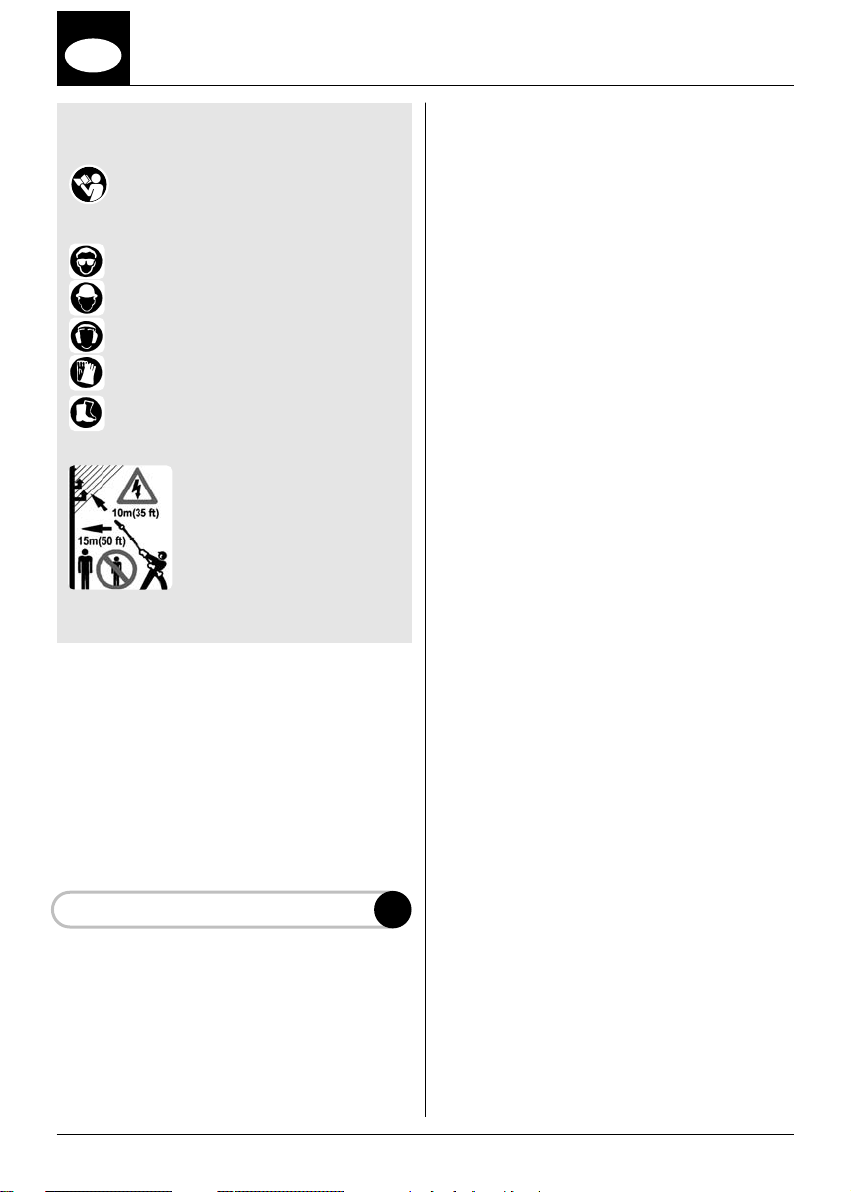
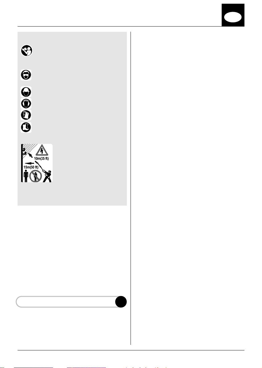
SPIEGAZIONE SIMBOLI
Leggere attentamente questo manuale
Abbigliamento di sicurezza richiesto:
1 - Occhiali di protezione in alternativa
visiera protettiva omologata
2 - Casco protettivo omologato
3 - Cuffie di protezione omologate
4 - Guanti omologati
5 - Stivali antisdrucciolo di sicurezza
omologati
- La macchina non è stata
progettata per isolare
elettricamente in caso di
contatto con linee elettriche
sopra elevate sotto tensione.
Non avvicinare mai l’utensile a
meno di 10 metri dalle linee
elettriche. Tenere persone e
animali lontano 15 metri.
INDICE
A - INFORMAZIONI GENERALI
B - DESCRIZIONE DEI COMPONENTI
C - NORME DI SICUREZZA
D - MONTAGGIO BARRA E CATENA
E - INSTALLAZIONE POTATORE
F - AVVIAMENTO ED USO
G - MANUTENZIONE
H - AFFILATURA CATENA
INFORMAZIONI GENERALI
Il potatore professionale EMAK EP120 ed
EP120EF è un dispositivo di taglio a catena che
si può installare su aste rigide o telescopiche in
funzione alle operazioni di taglio che si
intendono eseguire.
Le caratteristiche di taglio dell’EP120 /EP120EF
sono quanto di più innovativo oggi esiste nel
settore della potatura, ciò è possibile grazie al
posizionamento angolare che può essere
implementato tra coppia conica e l’asse della
lama di taglio.
Queste regolazioni possono essere effettuate a
piacere dall’operatore entro un campo da O° a
90° con step di 22.5°. Vedere la figura di
riferimento E.
Il potatore professionale EMAK nell’uso in
posizione angolare, consente all’operatore di
osservare la posizione di contatto con il ramo da
tagliare, ed eseguire quindi una perfetta
operazione di potatura.
Inoltre grazie alla posizione angolare
implementata sulla coppia conica, l’operatore,
mantenendo la stessa postazione di lavoro, può
eseguire operazioni di taglio di rami altrimenti
inaccessibili.
Il sistema di potatura EP120/EP120EF apre un
campo nuovo su come condurre operazioni di
taglio; la sua elevata manovrabilità in altezza si
abbina a notevoli capacità di recidere gli arbusti
al suolo ed al taglio di rami al di sotto del piano
di calpestio.
L’operazione di installazione del potatore
professionale si esegue inserendo sull’asta la
coppia conica, rispettando la posizione della vite
(A) che deve incontrare il foro relativo presente
sull’asta; serrare con moderazione, mediante la
chiave da 4 mm in dotazione
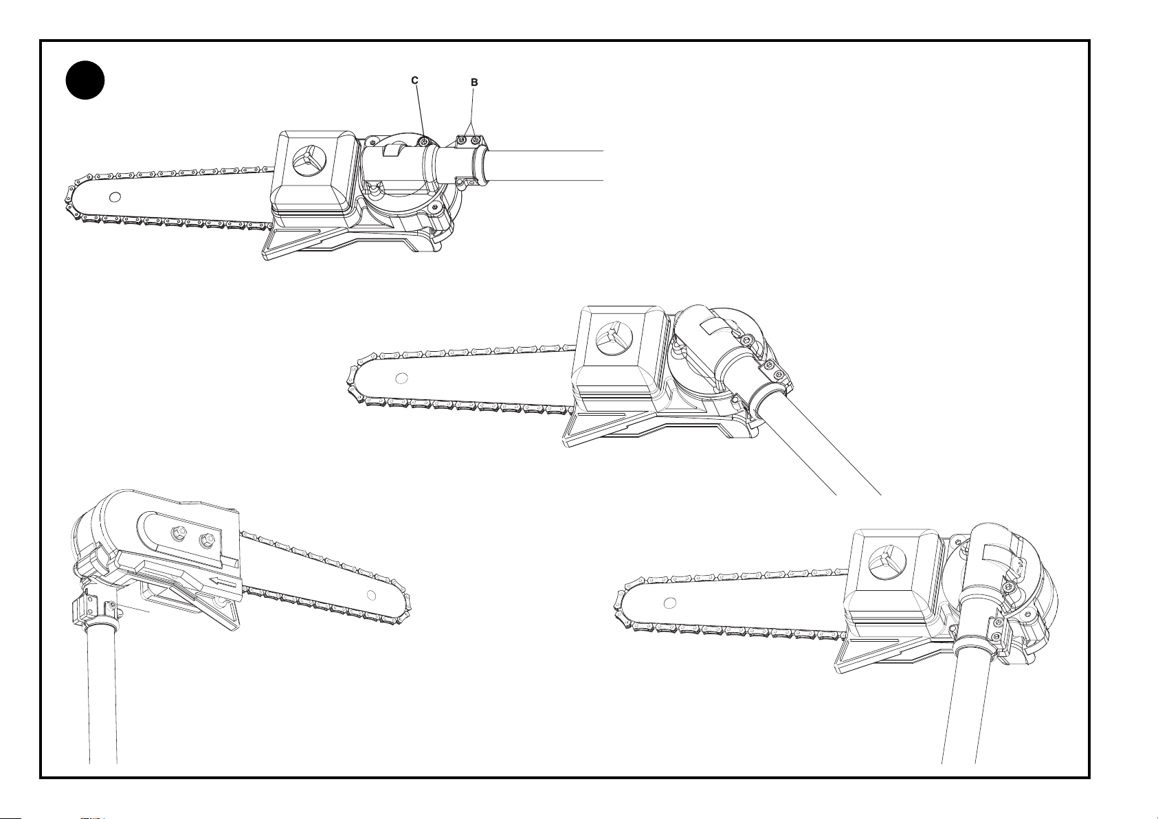
Avvitare le due viti (B) che costituiscono il
bloccaggio assiale della coppia conica sull’asta
serrando con chiave da 4 mm fornita in
dotazione.
Questo serraggio deve essere eseguito
accostando in successione le due viti per poi
eseguire un serraggio finale rapportato ad un
sforzo normale che si può esercitare sulla chiave
con il solo uso della mano.
La regolazione angolare della coppia conica si
esegue allentando la vite (C) con la chiave da
5 mm fornita in dotazione, operando come
segue:
• Allentare la vite fino a sentire dopo circa due
giri che la vite stessa oppone resistenza, in
questo modo la coppia conica è libera di
ruotare sulla propria ghiera.
• Posizionare la coppia conica secondo l’angolo
desiderato, si percepisce durante questa
operazione lo scatto meccanico di ogni step di
posizionamento raggiunto; fermarsi alla
posizione angolare desiderata per la attività di
potatura previste.
• Avvitare di nuovo la vite (C) con la chiave in
dotazione serrando con la forza che si può
esercitare sulla chiave con il solo uso della
mano.
A
4
I
3Non effettuare operazioni di taglio con angolo
superiore a 60° con il suolo.
4 Non utilizzare scale o posizioni incerte, tenete
pulita la zona di lavoro per facilitare un
eventuale allontanamento. E’ vietato salire
sugli alberi con il potatore, è consentito solo
su cabina con sollevamento idraulico.
MONTAGGIO BARRA E CATENA
Il potatore professionale EMAK viene fornito con
barra e catena installati e regolati in fabbrica.
Per le operazioni di sostituzione della barra e
catena, oppure per eseguire le operazioni di
riaffilature della catena, procedere nel seguente
modo:
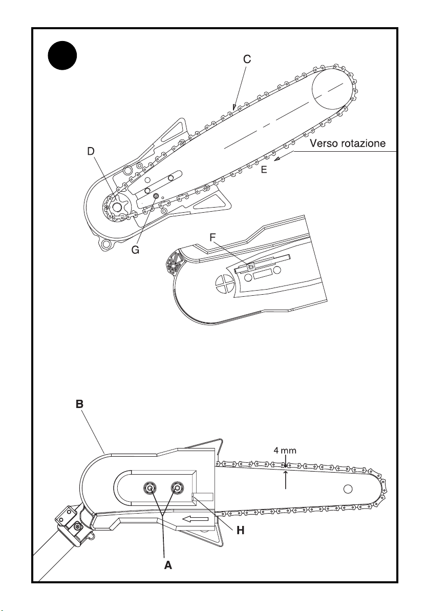
1 Svitare i due dadi (A) e rimuovere il carter
catena (B).
2 Alloggiare la catena nella gola (C) della barra e
contemporaneamente sul rocchetto (D) di
trasmissione, guardando ora l’assieme barra e
catena assicurarsi che la catena sia con i
taglienti rivolti nel verso orario (E).
3 Appoggiare il carter copricatena tenendo
tenendolo premuto contro la barra ed avvitare
la vite di regolazione (H), affinché il nottolino
tendi catena (F) entri nel foro (G) della barra.
4 Avvitare con leggero precarico i dadi (A) sul
coperchio. Agire sulla vite tendi catena (H)
ruotando in senso orario, verificare la tensione
della catena in modo che sollevando la stessa
sia appena visibile l’interno della maglia per
circa 4 mm.
La giusta regolazione è eseguita quando la
catena scorre liberamente.
Serrare a fondo i dadi (A).
INSTALLAZIONE DEL POTATORE
PROFESSIONALE EMAK
EP120/EP120EF
1Inserire la coppia conica sull’asta di
trasmissione.
2 Posizionare la vite laterale della coppia conica
in corrispondenza del foro che si trova a circa
33 mm dell’estremità del tubo di trasmissione.
3 Avvitare la vite (A) che impegna la coppia
conica con il foro sul tubo di trasmissione;
serrare con moderazione per consentire
l’impegno della vite nel relativo foro.
•Per effettuare le operazioni di riposizio-
namento, ripetere la stessa sequenza.
Le zone di potatura che si raggiungono con il
potatore professionale EMAK sono le più
svariate, sta all’operatore impostare con
sicurezza la posizione più adeguata al suolo ed
eseguire gran parte del lavoro senza spostarsi.
Nella condizione di lavoro di taglio di rami al
suolo, è necessario evitare che la lama vada a
contatto con sassi o terra.
Nella potatura in alto assumere una posizione
sicura a terra, ed evitare di sostare al di sotto
del ramo da tagliare.
NON UTILIZZARE SCALE E
NON ARRAMPICARSI SUGLI ALBERI
DESCRIZIONE DEI COMPONENTI
1 - BARRA
2 - CATENA
3 - TAPPO OLIO
4 - SERBATOIO OLIO
5 - DADI FISSAGGIO BARRA
6 - CARTER CATENA
7 - VITE REGOLAZIONE CATENA
8 - COPPIA CONICA ANGOLARE REGOLABILE
9 - VITE DI BLOCCO/SBLOCCO COPPIA
CONICA
NORME DI SICUREZZA
Il potatore EP120 ed EP120EF può essere
installato solo su macchine ed aste rigide o
telescopiche di produzione EMAK.
Durante l’approntamento dell’area di lavoro,
spegnere sempre il motore del potatore
Applicare il copri barra nelle fasi di trasporto
della macchina.
1 E’ necessario utilizzare con attenzione le
informazioni riportate.
2 Non effettuate operazioni di taglio nelle
vicinanze di linee ad alta tensione pericolo di
scossa.
NON OPERATE A DISTANZE INFERIORI A
10 METRI DALLE LINEE ELETTRICHE.
Non operate ad una distanza inferiore a 15
metri, da animali o persone, il campo
d’azione del potatore può mettere in
pericolo le stesse.
B
C
D
E

5
I
Avvitare con successivi accostamenti le viti (B)
utilizzando la chiave da 4 mm fornita in
dotazione. Serrare con un forza equivalente a
quello che è possibile esercitare sulla chiave
con il solo uso della mano. Non è necessario
in questa operazione esagerare con la forza
di serraggio perché la forza che si produce
con questo tipo di fissaggio è sufficiente a
garantire la stabilità dell’assieme potatore
con asta di sostegno.
AVVIAMENTO ED USO
1Il potatore è munito di pompa di lubrificazione
della catena che assicura la quantità
necessaria alla catena durante il moto.
La quantità che la pompa eroga è stata dosata
per ridurre al minimo l’impatto con l’ambiente,
ed utilizzare nello stesso tempo la quantità
necessaria alla lubrificazione della catena.
2 Per un corretto funzionamento usare oli di
media viscosità, non usare olio di recupero,
previo danneggiamento della pompa.
3 Durante l’avviamento della macchina
assicurarsi che la catena non tocchi nessun
oggetto compreso il terreno. Per le istruzioni di
avvio riferirsi alle istruzioni in dotazione della
macchina.
Consigli generali per una corretta
esecuzione del taglio.
Si rammenta che il potatore professionale
EMAK ha la capacità di regolazione dell’angolo
di taglio tra 0° e 90°. Questa caratteristica offre
all’operatore la possibilità di poter decidere
con quale angolo di taglio ritiene più
opportuno affrontare la potatura, permettendo
all’operatore stesso di osservare con
precisione la posizione della lama sul ramo. Il
taglio in questo caso avviene procedendo
dall’alto in basso con il vantaggio di non dover
effettuare nessuno sforzo verso il taglio da
eseguire perché esso avviene lasciando che
sia il peso stesso della macchina sostenuta
dall’operatore a gravare sul taglio in
esecuzione. Si rammenta di non sostare al di
sotto del ramo da tagliare. Per evitare la
scortecciatura che si può verificare verso la
fine dell’operazione di taglio, eseguire in
precedenza sul lato inferiore del ramo stesso,
un taglio. Se il ramo è abbastanza grande
tagliare in più pezzi per alleggerirlo e gestire
meglio il lavoro. Se necessario ripassare il
taglio.
MANUTENZIONE PERIODICA
Le manutenzioni vanno effettuate con il motore
spento. Assicurarsi che l’interruttore della
macchina sia in posizione “STOP”.
Regolare la tensione della catena seguendo le
indicazione del capitolo “D”.
Una catena nuova può richiedere una
regolazione più frequente. Le regolazioni
possono essere eseguite con più accortezza
rimuovendo il potatore dall’asta, ciò consente di
effettuare la manutenzione del potatore in
officina.
AFFILATURA CATENA
L’affilatura della catena è una operazione che si
può eseguire con il potatore installato oppure
rimosso dalla macchina.
Eseguire le operazioni di rimozione catena
oppure di affilatura con macchina spenta ed
interruttore in posizione “STOP”.
L’affilatura deve essere eseguita con una lima a
tondino, di diametro 4 mm (5/32”), per la catena
mod. OREGON 90SG039E che è installata sul
vostro potatore. Procurarsi un guida lime con il
quale impegnare la catena ed eseguire
alternativamente nel dente destro e sinistro
l’affilatura con un angolo tra i 55°/60°. In
mancanza di un guida lime, tendere la catena
sulla lama usando la vite di regolazione in modo
da tenere stabile la catena, ed eseguire
l’affilatura. Procedere con una lima piana per
ridurre l’altezza del limitatore che deve risultare
inferiore di 0.6 / 0.7 mm dal piano del tagliente.
Verificare con un calibro l’operazione.
F
G
H
6
GB
EXPLANATION OF SYMBOLS
Read carefully through this manual.
Required safety clothing:
1- Protective eyewear, or approved visor
2 - Approved hard hat
3 - Approved ear defenders
4 - Approved gloves
5 - Approved non-slip safety boots
- The machine is not designed
to provide electrical insulation
in the event of contact with
overhead power lines. Never
operate the pruner at less than
10 metres from electric power
lines.
Allow bystanders and animals
no closer than 15 metres.
CONTENTS
A- GENERAL INFORMATION
B- DESCRIPTION OF COMPONENTS
C- SAFETY INSTRUCTIONS
D- BAR AND CHAIN ASSEMBLY
E- PRUNER INSTALLATION
F- STARTING AND OPERATION
G- MAINTENANCE
H- SHARPENING THE CHAIN
GENERAL INFORMATION
The EMAK EP120 / EP120EF professional pruner
is a small chainsaw that can be mounted to a
fixed pole or a telescopic pole, according to the
nature of the cutting operations being carried
out.
The operating features of the EP120 / EP120EF
reflect everything that is most innovative today in
the pruning sector, and this is attributable to the
facility of varying the angular position of the
bevel drive interconnecting the pole and the
chain bar of the saw.
The adjustments are made within an arc of 90°,
through angular steps of 22°, and can be
selected at will by the operator. See figure (E).
With the EMAK professional pruner in an angled
position, the operator has a clear view of the
position of contact with the branch, so that
pruning cuts can be made cleanly and effectively.
In addition, thanks to the angular adjustment
allowed by the bevel drive, the operator can cut
through branches that would otherwise be
inaccessible, while continuing to stand in the
same position.
The EP120 / EP120EF pruning system opens up
new possibilities for faster and more efficient
cutting; its superior manoeuvrability overhead
combines with a significant capacity for cutting
shrubs at ground level, and branches below
ground level.
The operation of installing the professional
pruner is accomplished by fitting the bevel drive
to the pole, taking care over the position of the
screw (A) which must align with a relative hole in
the pole; secure the screw using the 4 mm key
provided, without overtightening
Secure the two screws (B) by which the bevel
drive is clamped axially to the pole, tightening
with the 4 mm key provided.
This is done by snugging the two screws in
sequence and finally tightening them, but not
overtightening, applying a moderate force that
can be transmitted through the key by normal
hand pressure.
The angular adjustment of the bevel drive is
effected by loosening the screw (C) with the 5
mm key provided, proceeding as follows:
• Loosen the screw to the point at which the
screw offers resistance (after about two turns);
the bevel drive will now be free to rotate on its
collar.
• Position the bevel drive at the desired angle.
Moving the drive through the 90° arc, a click
will be heard as each of the stable positions is
engaged; stop at the position best suited to
the type of pruning operation being carried
out.
• Retighten the screw (C) with the key provided,
applying a moderate force that can be
transmitted through the key by normal hand
pressure.
A

7
GB
•To reposition the saw, repeat the same
sequence of operations.
With the EMAK professional pruner, branches of
all shapes and sizes are rendered accessible for
cutting back or thinning; the operator need only
select a safe stance and pole angle, and most of
the cutting can be done while standing on the
same spot.
When cutting low branches near the ground,
be certain the chain does not make contact
with stones or soil.
When pruning high branches, take up a safe
position below and avoid standing directly
under the branch being cut.
DO NOT USE LADDERS, AND DO NOT CLIMB
INTO TREES
DESCRIPTION OF COMPONENTS
1 - BAR
2 - CHAIN
3 - OIL FILLER CAP
4 - OIL TANK
5 - BAR CLAMP NUTS
6 - CHAIN GUARD
7 - CHAIN ADJUSTMENT SCREW
8 - ADJUSTABLE BEVEL DRIVE
9 - BEVEL DRIVE LOCK / RELEASE SCREW
SAFETY INSTRUCTIONS
The EP120 / EP120EF pruner can be attached
only to machines with rigid or telescopic poles
made by EMAK.
Always switch off the engine of the pruner when
preparing the work area.
Fit the chain sheath when transporting the
machine.
1 The information given here must be read with
care.
2 Do not use the pruner near overhead power
lines, as there is a risk of electric shock.
DO NOT OPERATE THE PRUNER WITHIN
10 METRES OF ELECTRIC POWER LINES.
Make certain animals or bystanders are
kept at a distance of at least 15 metres, as
the reach of the pruner could place them at
risk.
3Do not elevate the pole to an angle greater
than 60° from the ground.
4 Do not use ladders or stand precariously, and
keep the work area clean and tidy to allow a
swift exit if necessary. Never climb into trees
with the pruner; if extra height is needed, a
hydraulically operated overhead access
platform must be used.
BAR AND CHAIN ASSEMBLY
The EMAK professional pruner is supplied with
bar and chain factory fitted and adjusted.
To replace the bar and chain, proceed as follows:
1 Loosen the two lock nuts (A) and remove the
chain guard (B).
2 Seat the chain in the groove (C) of the bar and
over the drive sprocket (D); first, viewing the
assembled bar and chain, make certain that
the chain is fitted with the cutting edges facing
in the clockwise direction (E).
3 Position the guard, keeping it tight against the
bar, then tighten the tensioner screw (H) so
that the chain tension pin (F) engages the hole
(G) in the bar.
4 Snug the nuts (A) against the guard, without
tightening fully. Turn the chain tensioner screw
(H) clockwise; check the tension of the chain,
ensuring that when lifted, the inside of the link
is just visible for about 4 mm.
The adjustment will be correct when the chain
runs freely on the bar.
Tighten the lock nuts (A).
INSTALLATION OF EMAK EP120 /
EP120EF PROFESSIONAL PRUNER
1Couple the bevel drive to the drive shaft.
2 Align the side screw of the bevel drive with the
hole located at 33 mm approx from the end of
the pole tube.
3 Fit the screw (A) anchoring the bevel drive to
the hole in the pole tube, and tighten
moderately so that the screw engages the
hole.
Tighten the screws (B) gradually, in alternating
sequence, using the 4 mm key provided. The
B
C
D
E
8
GB
force applied in tightening the screws should
be no more than can be transmitted through
the key by normal hand pressure. There is no
need to overtighten these screws, since the
force generated by the type of fastening
arrangement adopted is sufficient to
ensure the stability of the assembled
pruner and pole.
STARTING AND OPERATION
1The pruning saw is equipped with an oiler that
will feed the required amount of lubricant to
the chain automatically during operation.
The quantity of oil dispensed is metered in
such a way as to minimize environmental
impact while guaranteeing the amount needed
to keep the chain properly lubricated.
2 For smooth operation, use an oil of medium
viscosity; do not use reclaimed lubricating oil
as this could damage the pump.
3 Make certain, when starting the engine, that
the chain is clear of the ground and not
touching any object. For starting instructions,
refer to the manual accompanying the
machine.
General hints on correct cutting.
Remember that with the EMAK professional
pruner, the angle of the saw is adjustable through
90°. This means that the operator can decide
which is the best cutting angle to select for the
particular pruning job, and can also rely on a
clear and exact view of the chainsaw when
positioned on the branch to make the cut. The
cut in this instance is made from the top
downwards, with the advantage that no physical
effort need be applied through the line of the cut
since the weight of the machine itself, held by
the operator, is sufficient to carry the pruner
cleanly through the branch. Remember not to
stand directly beneath the branch being cut.
To prevent the bark from tearing, typically at the
end of a through-limb cut, make a shallow
undercut in the branch before making the main
downward pass.
For larger limbs, cut back by stages so as to
lighten the load and make the operation more
manageable. Make repeated passes along the
kerf if necessary.
PERIODIC MAINTENANCE
Never carry out maintenance operations with the
engine running. Make certain that the main
switch is positioned on “STOP”.
To adjust the chain tension, follow the procedure
indicated in heading “D”.
A new chain may need adjusting more frequently.
Adjustments can be made more effectively with
the pruner removed from the pole, as this will
allow the chainsaw components to be serviced
in a workshop.
SHARPENING THE CHAIN
The chain can be sharpened with the pruner
either attached to or removed from the pole of
the machine.
Never remove and/or sharpen the chain without
first shutting off the engine and setting the
switch to the “STOP” position.
In the case of the OREGON 90SG039E model
fitted to your machine, the chain is sharpened
with a rat-tail file of 4 mm (5/32”) diameter,
Procure a file guide applicable to the chain, and
file the right hand and left hand teeth in
alternation to an angle between 55° and 60°. If
no file guide is available, tension the chain on the
bar using the relative adjustment screw to hold it
stable, and proceed with the sharpening
operation. Use a flat file to reduce the height of
the limiter, which should be less than 0.6 / 0.7
mm from the plane of the cutting edge.
Check the teeth with a gauge.
F
G
H
9
F
EXPLICATION DES SYMBOLES
Lire attentivement ce manuel.
Vêtements de protection nécessaires :
1 - Lunettes de protection ou visière de
protection homologuée
2 - Casque homologué
3 - Oreillettes de protection homologuées
4 - Gants homologués
5 - Bottes antidérapantes de protection
homologuées
- L’appareil n’est pas conçu
pour isoler en cas de contact
avec des lignes électriques
suspendues sous tension. Ne
jamais approcher l’engin à
moins de 10 m des lignes
électriques.
Tenir les personnes et les
animaux à l’écart (15 m
minimum).
INDEX
A - INFORMATIONS GÉNÉRALES
B - DESCRIPTION DES COMPOSANTS
C - MESURES DE SÉCURITÉ
D - MONTAGE BARRE ET CHAÎNE
E -
INSTALLATION DE LA PERCHE ÉLAGUEUSE
F - MISE EN MARCHE ET MODE D’EMPLOI
G - ENTRETIEN
H - AFFÛTAGE DE LA CHAÎNE
INFORMATIONS GÉNÉRALES
La perche élagueuse professionnelle EMAK
EP120 / EP120EF est un dispositif de coupe à
chaîne qui peut être monté sur des tiges fixes ou
télescopiques en fonction des opérations de
coupe à effectuer.
Les caractéristiques de coupe de la EP120 /
EP120EF sont extrêmement innovatrices pour le
secteur actuel de l’élagage, grâce à la position
angulaire entre couple conique et axe de la lame
de coupe.
Ces réglages peuvent être effectués librement
par l’opérateur entre 0° et 90°, par crans de 22°.
Voir la figure de référence (E).
La perche élagueuse professionnelle EMAK,
utilisée dans la position angulaire, permet à
l’opérateur de contrôler la position de contact
avec la branche à couper et donc d’élaguer
correctement.
De plus, grâce à la position angulaire possible
sur le couple conique, l’opérateur peut couper
des branches qui, dans d’autres conditions
seraient inaccessibles, tout en gardant le même
poste de travail.
Le système d’élagage EP120 / EP120EF ouvre
de nouvelles possibilités sur la façon de
procéder aux opérations de taille ; sa
manoeuvrabilité en hauteur se marie à la
possibilité de couper les arbustes au sol et les
branches sous le niveau de piétinement.
Pour installer la perche élagueuse, introduire le
coupe conique sur la tige en respectant la
position de la vis (A) qui doit entrer dans l’orifice
correspondant sur la tige ; serrer modérément à
l’aide d’une clé de 4 mm fournie.
Serrer les deux vis (B) assurant le blocage axial
du couple conique sur la tige à l’aide de la clé de
4 mm fournie.
Procéder à ce serrage en approchant
successivement les deux vis pour passer ensuite
au serrage final en exerçant un effort manuel
normal sur la clé.
Procéder au réglage angulaire du couple conique
en desserrant la vis (C) avec la clé de 5 mm
fournie et en procédant de la façon suivante :
- Desserrer la vis jusqu’à sentir une résistance
après environ deux tours ; le couple conique
peut ainsi tourner librement sur sa bague.
- Placer le couple conique selon l’angle choisi ;
un déclic mécanique se produit à chaque
cran ; s’arrêter sur la position angulaire choisie
pour l’activité d’élagage prévue.
- Serrer de nouveau la vis (C) avec la clé fournie
en exerçant uniquement la force de la main.
- Pour repositionner l’outil, répéter la même
séquence.
La perche élagueuse professionnelle EMAK
permet d’atteindre les zones les plus diverses ;
A
10
F
l’opérateur doit tout simplement établir en toute
sécurité la position la plus appropriée par
rapport au sol et effectuer une grande partie du
travail sans se déplacer.
Pour couper les branches proches du sol,
éviter que la lame n’entre en contact avec des
cailloux ou de la terre.
Pour couper des branches en hauteur,
maintenir une position stable au sol et éviter
de rester sous la branche à couper.
NE PAS UTILISER D’ÉCHELLES ET NE PAS
GRIMPER SUR LES ARBRES
DESCRIPTION DES COMPOSANTS
1 - BARRE
2 - CHAÎNE
3 - BOUCHON HUILE
4 - RÉSERVOIR HUILE
5 - ÉCROUS DE FIXATION BARRE
6 - CARTER CHAÎNE
7 - VIS DE RÉGLAGE CHAÎNE
8 -
COUPLE CONIQUE ANGULAIRE RÉGLABLE
9 - VIS DE BLOCAGE / DÉBLOCAGE COUPLE
CONIQUE
MESURES DE SÉCURITÉ
La perche élagueuse EP120 / EP120EF ne peut
être installée que sur des machines à tige fixe ou
télescopique EMAK.
Lors de la préparation de l’aire de travail, le
moteur doit rester éteint.
Monter la protection de la barre pour transporter
la machine.
1 Respecter les conseils fournis.
2 Ne couper aucune branche à proximité des
lignes haute tension : risque d’électrocution.
NE PAS S’APPROCHER À MOINS DE 10 M
DES LIGNES ÉLECTRIQUES.
Maintenir une distance minimum de 15 m
par rapport aux animaux ou aux
personnes: tenir compte du champ
d’action de la perche élagueuse.
3Ne pas couper à un angle supérieur à 60° par
rapport au sol.
4 Ne pas utiliser d’échelles ou se mettre sur
une position instable; s’assurer que la zone
de travail est propre pour pouvoir s’éloigner
facilement en cas de danger. Il est interdit de
monter sur les arbres avec la perche
élagueuse ; ceci n’est permis que sur des
cabines à relevage hydraulique.
MONTAGE DE LA BARRE
ET DE CHAÎNE
La perche élagueuse professionnelle EMAK est
fournie avec une barre et une chaîne installées et
réglées à l’usine.
Pour remplacer la barre et la chaîne, procéder de
la façon suivante:
1 Dévisser les deux écrous (A) et déposer le
carter de la chaîne (B).
2 Installer la chaîne dans la gorge (C) de la
guide et, simultanément, sur le rochet (D) de
transmission; contrôler l’ensemble
guide/chaîne pour s’assurer que la partie
coupante de la chaîne est tournée dans le
sens horaire (E).
3 Placer le carter de protection de la chaîne en
le maintenant contre la barre et serrer les vis
de réglage (H) afin que le cliquet tendeur de
chaîne (F) entre dans l’orifice (G) de la barre.
4 Visser légèrement les écrous (A) sur le
couvercle. Agir sur la vis du tendeur de
chaîne (H) en la tournant dans le sens des
aiguilles d’une montre ; vérifier la tension de
la chaîne de sorte que l’on voie l’intérieur du
maillon sur 4 mm env. en la soulevant.
La chaîne est réglée correctement lorsqu’elle
peut coulisser librement.
Serrer à fond les écrous (A).
INSTALLATION DE LA PERCHE
ÉLAGUEUSE PROFESSIONNELLE
EMAK EP120 / EP120EF
1Introduire le couple conique sur la tige de
transmission.
2 Placer la vis latérale du couple conique en
face de l’orifice qui se trouve à env. 33 mm de
l’extrémité du tuyau de transmission.
B
C
D
E
11
F
3Serrer la vis (A) qui bloque le couple conique
sur l’orifice du tuyau de transmission ; serrer
modérément pour permettre à la vis d’entrer
dans l’orifice correspondant.
Serrer progressivement les vis (B) à l’aide de
la clé de 4 mm fournie. Serrer en exerçant
uniquement la force de la main. Pour cette
opération, il n’est pas nécessaire de
serrer trop fort car la force qui se produit
avec ce type de fixation suffit à garantir la
stabilité de l’ensemble perche/tige de
soutien.
MISE EN MARCHE
ET MODE D’EMPLOI
1La perche élagueuse est dotée d’une pompe
de lubrification de la chaîne qui assure la
quantité d’huile nécessaire à la chaîne
pendant qu’elle tourne.
La quantité d’huile que la pompe déverse à
été dosée de sorte à réduire le plus possible
l’impact avec l’environnement et à utiliser, par
la même occasion, la quantité nécessaire à la
lubrification de la chaîne.
2 Pour assurer un fonctionnement correct,
utiliser des huiles à viscosité moyenne ; ne
pas utiliser d’huile de récupération pour ne
pas endommager la pompe.
3 Lors de la mise en marche de la machine,
s’assurer que la chaîne ne touche aucun
objet, y compris le terrain. Pour les
instructions concernant la mise en marche,
consulter le manuel fourni avec la machine.
Conseils généraux pour une coupe
parfaite.
La perche élagueuse professionnelle EMAK
donne la possibilité de régler l’angle de coupe
de 0°à90°.Cette caractéristique permet à
l’opérateur de décider à quel angle de coupe
procéder à l’élagage afin de contrôler avec
précision la position de la lame sur la
branche. Dans ce cas, la coupe a lieu de haut
en bas avec l’avantage de ne devoir fournir
aucun effort car il suffit de laisser le poids de
la machine accomplir la coupe. Se rappeler
de ne pas rester sous la branche à couper.
Pour éviter d’écorcer la branche - en fin
d’opération - effectuer préalablement une
coupe sur la partie inférieure de la branche.
Si la branche est assez grande, la couper en
plusieurs tronçons pour l’alléger et mieux
gérer le travail. Si nécessaire, repasser la
coupe.
ENTRETIEN PÉRIODIQUE
Procéder aux opérations d’entretien moteur
éteint. S’assurer que l’interrupteur de la machine
est sur la position “STOP”.
Régler la tension de la chaîne en suivant les
indications du point “D”.
Une chaîne neuve doit être réglée plus
fréquemment. Pour un réglage plus précis,
déposer la perche de la tige afin de procéder aux
opérations d’entretien en atelier.
AFFÛTAGE DE LA CHAÎNE
Il est possible de procéder à l’affûtage de la
chaîne que la perche soit installée ou déposée
de la machine.
Déposer la chaîne ou affûter en condition de
machine à l’arrêt et interrupteur sur la position
“STOP”.
Procéder à l’affûtage avec une lime arrondie, de
4 mm de diamètre (5/32”), pour la chaîne mod.
OREGON 90SG039E installée sur la perche.
Utiliser un guide lime pour bloquer la chaîne et
affûter la dent droite et la dent gauche à un angle
d’environ 55°/60°. Sans guide lime, tendre la
chaîne sur la barre à l’aide de la vis de réglage
afin de maintenir la chaîne et procéder à
l’affûtage. Utiliser une lime plate pour réduire la
hauteur du limiteur qui doit résulter en-dessous
du plan de coupe de 0,6/0,7 mm.
Vérifier l’opération avec une jauge.
F
G
H

12
D
ERKLÄRUNG DER SYMBOLE
Dieses Handbuch aufmerksam
durchlesen.
Erforderliche Sicherheitskleidung:
1 - Schutzbrille, oder alternativ ein
zugelassenes Schutzvisier
2 - Zugelassener Schutzhelm
3 - Zugelassener Gehörschutz mit Bügel
4 - Zugelassene Handschuhe
5 - Zugelassene, rutschfeste Sicherheitsstiefel
- Die Maschine ist nicht zur
elektrischen Isolierung bei
Kontakt mit spannungsführenden
Überlandleitungen ausgelegt.
Benutzen Sie das Werkzeug
daher nie in weniger als 10
Meter Abstand von
Stromleitungen.
Halten Sie Personen und Tiere in
15 Meter Entfernung.
INHALTSVERZEICHNIS
A - ALLGEMEINE INFORMATIONEN
B - BESCHREIBUNG DER EINZELNEN
BAUTEILE
C - SICHERHEITSVORSCHRIFTEN
D - MONTAGE VON SCHIENE UND KETTE
E - ANBAU DES HOCHENTASTERS
F - INBETRIEBNAHME UND GEBRAUCH
G - WARTUNG
H - SCHLEIFEN DER KETTE
ALLGEMEINE INFORMATIONEN
Der Profi-Hochentaster EMAK EP120 / EP120EF ist
ein kettengetriebenes Baumschnittwerkzeug, das je
nach den auszuführenden Schneidarbeiten an
einen feststehenden oder an einen Teleskopschaft
angebaut werden kann.
Dank der verstellbaren Winkelstellung zwischen
Kegelradgetriebe und Sägeblattachse bietet der
Hochentaster EP120 / EP120EF die innovativsten
Schneideigenschaften, die heute im Bereich der
Baumpflege zur Verfügung stehen.
Diese Einstellungen können nach Belieben des
Bedieners in einem Bereich von 0° bis 90° mit
Schritten von je 22° vorgenommen werden. Siehe
Abbildung (E).
Bei Verwendung in Winkelstellung gestattet der
Profi-Hochentaster von EMAK dem Benutzer einen
freien Blick auf die Berührungsstelle mit dem zu
schneidenden Ast und folglich einen perfekten
Baumschnitt.
Dank der verstellbaren Winkelstellung zum
Kegelradgetriebe kann der Bediener Schnitte an
sonst unerreichbaren Ästen durchführen, ohne die
Arbeitsposition zu verändern.
Das Baumschnittsystem EP120 / EP120EF eröffnet
vollkommen neue Möglichkeiten zur Durchführung
von Baumpflegearbeiten; zu seiner
ausgezeichneten Manövrierbarkeit beim Arbeiten in
der Höhe kommt seine beachtliche
Leistungsfähigkeit beim Schneiden von Büschen
am Boden und von Ästen unterhalb der Gehebene.
Der Anbau des Profi-Hochentasters erfolgt durch
Anbringung des Kegelradgetriebes am Schaft.
Dabei ist auf die Position der Schraube (A) zu
achten, die mit dem entsprechenden Bohrloch am
Schaft zusammenfallen muss; mit dem
mitgelieferten 4-mm-Schlüssel mäßig anziehen
Die zwei Schrauben (B), die zur axialen Befestigung
des Kegelradgetriebes am Schaft dienen, zudrehen
und mit dem mitgelieferten 4-mm-Schlüssel
anziehen.
Dazu müssen die zwei Schrauben nacheinander
zuerst leicht angeschraubt, und dann endgültig
angezogen werden. Der Anzug muss mit dem
normalen Kraftaufwand, der mit der bloßen Hand
auf den Schlüssel ausgeübt werden kann, erfolgen.
Zur Regulierung der Winkelstellung des
Kegelradgetriebes wird die Schraube (C) mit dem
mitgelieferten 5-mm-Schlüssel gelockert.
Folgendermaßen vorgehen:
- Die Schraube lockern, bis nach etwa zwei
Umdrehungen zu spüren ist, dass die Schraube
Widerstand leistet. Das Kegelradgetriebe lässt
sich nun frei an seiner Überwurfmutter drehen.
- Während das Kegelradgetriebe in den
gewünschten Winkel gedreht wird, ist bei jedem
Stellschritt ein mechanisches Einrastgeräusch zu
hören. Bei der für die durchzuführenden
A

13
D
Schneidarbeiten geeigneten Winkelstellung
anhalten.
- Die Schraube (C) mit dem mitgelieferten
Schlüssel wieder zudrehen. Dabei mit dem
Kraftaufwand, der mit der bloßen Hand auf den
Schlüssel ausgeübt werden kann, anziehen.
- Um das Werkzeug wieder zu positionieren,
denselben Vorgang wiederholen.
Mit dem Profi-Hochentaster von EMAK können die
unterschiedlichsten Arbeitsbereiche erreicht
werden; der Bediener selbst wählt unter sicheren
Bedingungen die geeignetste Arbeitshaltung zum
Boden, in der er den größten Teil der Arbeit
durchführen kann, ohne seine Position zu ändern.
Bei Schneidarbeiten an bodennahen Ästen
muss vermieden werden, dass das Sägeblatt
Steine oder den Boden berührt.
Beim Schneiden von hohen Ästen muss eine
sichere Stellung am Boden eingenommen
werden. Nicht unter dem zu schneidenden Ast
stehen bleiben.
KEINE LEITERN BENUTZEN UND NICHT AUF
DIE BÄUME KLETTERN
BESCHREIBUNG
DEREINZELNEN BAUTEILE (B)
1 - SCHIENE
2 - KETTE
3 - ÖLDECKEL
4 - ÖLTANK
5 - BEFESTIGUNGSMUTTERN DER SCHIENE
6 - KETTENGEHÄUSE
7 - KETTEN-STELLSCHRAUBE
8 - VERSTELLBARES ANGEWINKELTES
KEGELRADGETRIEBE
9 - SPERRSCHRAUBE DES
KEGELRADGETRIEBES
SICHERHEITSVORSCHRIFTEN
Der Hochentaster EP120 / EP120EF kann nur an den
von EMAK gebauten Maschinen mit feststehendem
oder Teleskopschaft angebaut werden.
Während der Vorbereitung des Arbeitsbereichs muss
der Motor des Hochentasters immer abgeschaltet
werden.
Zum Transport der Maschine immer die
Schienenabdeckung anbringen.
1 Die angegebenen Hinweise sind strikt zu
befolgen.
2 Führen Sie keine Schneidarbeiten in der Nähe
von Hochspannungsleitungen durch -
Stromschlaggefahr!
ARBEITEN SIE IN MINDESTENS 10 METER
ABSTAND VON STROMLEITUNGEN.
Arbeiten Sie in mindestens 15 Meter Abstand
von Tieren oder Personen, da diese innerhalb
der Reichweite des Hochentasters gefährdet
werden können.
3Führen Sie keine Schneidarbeiten in einem
größeren Winkel als 60° zum Boden durch.
4 Benutzen Sie keine Leitern und arbeiten Sie nie
in unsicherer Arbeitshaltung. Halten Sie den
Arbeitsbereich stets sauber, um sich eventuell
rasch entfernen zu können. Es ist verboten, mit
dem Hochentaster auf die Bäume zu klettern;
zulässig ist nur eine hydraulisch angehobene
Arbeitsbühne.
MONTAGE VON SCHIENE
UND KETTE
Der Profi-Hochentaster EMAK wird mit Schiene und
Kette ausgeliefert, die im Werk installiert und
eingestellt werden.
Zum Ersatz von Schiene und Kette folgendermaßen
vorgehen:
1 Die zwei selbstsperrenden Muttern (A) lösen
und das Kettengehäuse (B) entfernen.
2 Die Kette in die Nut (C) des Schwert und
gleichzeitig am Umlenkstern (D) einsetzen; bei
Betrachten der Einheit Schwert/Kette müssen
die Schneidzähne der Kette im Uhrzeigersinn
ausgerichtet sein (E).
3 Das Kettengehäuse gegen die Schiene drücken
und die Stellschraube (H) zudrehen, bis der
Kettenspannbolzen (F) im Bohrloch (G) an der
Schiene einrastet.
4 Die Muttern (A) nicht zu fest an der Abdeckung
festschrauben. Die Kettenspannschraube (H) im
Uhrzeigersinn drehen; sicherstellen, dass die
Kette so gespannt ist, dass bei Anheben der
Kette das Innere des Kettenglieds für ca. 4 mm
sichtbar ist.
Die Einstellung ist korrekt, wenn die Kette frei
läuft.
Die Muttern (A) fest anziehen.
B
C
D

14
D
ANBAU DES PROFI-
HOCHENTASTERS
EMAK EP120 / EP120EF (E)
1Das Kegelradgetriebe an der Übertragungsstange
aufsetzen.
2 Die seitliche Schraube des Kegelradgetriebes auf
Höhe des etwa 33 mm vom Ende der
Übertragungsstange entfernten Bohrloches
positionieren.
3 Die Schraube (A), mit der das Kegelradgetriebe
am Bohrloch der Übertragungsstange blockiert
wird, zudrehen. Nicht zu fest anziehen, damit die
Schraube im Bohrloch eingreifen kann.
Die Schrauben (B) nacheinander mit dem
mitgelieferten 4-mm-Schlüssel anziehen. Mit dem
Kraftaufwand anziehen, der mit der bloßen Hand
auf den Schlüssel ausgeübt werden kann. Es ist
nicht notwendig, die Schrauben allzu fest
anzuziehen, da die Kraft, die mit dieser Art von
Befestigung erzielt wird, ausreicht, um die
Stabilität des Hochentasters mit der Stange zu
gewährleisten.
INBETRIEBNAHME UND GEBRAUCH
1Der Hochentaster ist mit einer Pumpe für die
Kettenschmierung ausgestattet, die während des
Betriebs die Zufuhr der erforderlichen Ölmenge
zur Kette sicherstellt.
Die von der Pumpe abgegebene Ölmenge ist so
dosiert, dass die Umweltbelastung auf ein
Minimum beschränkt, und gleichzeitig die für die
Kettenschmierung erforderliche Menge verwendet
wird.
2 Für einen einwandfreien Betrieb Öle mit mittlerer
Viskosität verwenden. Kein recyceltes Öl
verwenden, um die Pumpe nicht zu beschädigen.
3 Bei Inbetriebnahme der Maschine muss
sichergestellt werden, dass die Kette weder
irgendwelche Gegenstände, noch den Boden
berührt. Bezüglich der Anleitungen zur
Inbetriebnahme wird auf das Handbuch
verweisen, das der Maschine beiliegt.
Allgemeine Ratschläge für eine korrekte
Schnittausführung.
Der Profi-Hochentaster EMAK bietet die
Möglichkeit, den Schneidwinkel zwischen 0° und
90° einzustellen. Dank dieser Besonderheit kann
der Benutzer selbst entscheiden, mit welchem
Schneidwinkel er die Schneidarbeiten am besten
ausführen, und dabei die Position des Sägeblatts
am Ast genau überblicken kann. Der Schnitt
erfolgt in diesem Fall von oben nach unten, mit
dem Vorteil, keine Kraft auf den Schnitt ausüben
zu müssen, da das Gewicht der vom Benutzer
getragenen Maschine auf dem durchzuführenden
Schnitt lastet. Niemals unter dem zu
schneidenden Ast arbeiten.
Um das Anreißen der Rinde am Ende des
Schneidvorgangs zu verhindern, sollte der Ast an
der Unterseite vorher angeschnitten werden.
Besonders große Äste sollten in mehrere kleinere
Stücke getrennt werden, um ihr Gewicht zu
reduzieren und die Arbeit zu erleichtern. Falls
erforderlich den Schnitt nachbessern.
REGELMÄSSIGE WARTUNG
Für sämtliche Wartungseingriffe muss der Motor
abgeschaltet werden. Sicherstellen, dass der
Schalter der Maschine auf “STOP” steht.
Die Kettenspannung anhand der Markierung von
Punkt “D” regulieren.
Eine neue Kette muss unter Umständen häufiger
reguliert werden. Die Einstellungen können präziser
durchgeführt werden, wenn der Hochentaster von
der Stange entfernt wird, auf diese Weise kann der
Hochentaster in der Werkstatt gewartet werden.
SCHLEIFEN DER KETTE
Das Schleifen der Kette ist sowohl am angebauten
als auch an dem von der Maschine getrennten
Hochentaster möglich.
Zum Entfernen oder Schleifen der Kette muss die
Maschine abgeschaltet sein und der Schalter auf
“STOP” stehen.
Schleifen Sie die Kette mit einer Rundfeile mit
Durchmesser 4 mm (5/32”) für die Kette Mod.
OREGON 90SG039E, die an Ihrem Hochentaster
montiert ist. Verwenden Sie eine Feilenführung, mit
der die Kette blockiert wird, und schleifen Sie
abwechselnd im rechten und linken Schneidzahn
mit einem Winkel von 55°/60°. Sollten Sie keine
Feilenführung zur Hand haben, spannen Sie die
Kette an der Schiene mithilfe der Stellschraube so,
dass die Kette während des Schleifens festgehalten
wird. Anschließend mit einer Flachfeile die Höhe
des Tiefenbegrenzers verringern. Diese muss von
der Schneidebene geringer als 0,6 / 0,7 mm sein.
Den Vorgang mithilfe einer Lehre überprüfen.
F
G
H
E

15
E
EXPLICACIÓN DE LOS SÍMBOLOS
Leer atentamente este manual.
Elementos de seguridad
homologados que deben utilizarse:
1 - Gafas o visor
2 - Casco
3 - Auriculares
4 - Guantes
5 - Botas antideslizantes
- La máquina no está
protegida del contacto con
líneas eléctricas aéreas. No la
acerque nunca a menos de
10 metros de las líneas
eléctricas.
Evite que cualquier persona o
animal se acerque a menos de
15 metros.
ÍNDICE
A- INFORMACIÓN GENERAL
B- DESCRIPCIÓN DE LOS COMPONENTES
C- NORMAS DE SEGURIDAD
D- MONTAJE DE LA ESPADA Y LA CADENA
E- MONTAJE DE LA PODADORA
F- PUESTA EN MARCHA Y UTILIZACIÓN
G- MANTENIMIENTO
H- AFILADO DE LA CADENA
INFORMACIÓN GENERAL
La podadora profesional EMAK EP120 /
EP120EF es un dispositivo de corte con cadena
que puede acoplarse a un tubo fijo o telescópico
según la aplicación prevista.
La máquina ofrece las prestaciones de corte
más avanzadas que existen en este sector, ya
que permite variar el ángulo entre el par cónico y
el eje de la espada.
La regulación puede realizarse entre 0° y 90° a
intervalos de 22°. Vea la figura (E).
Con el sistema de corte en ángulo es posible ver
claramente el punto de contacto con la rama y
realizar el corte con mayor precisión.
Esta característica también permite,
manteniendo la misma posición de trabajo,
cortar ramas que de otra forma serían
inaccesibles.
El sistema EP120 / EP120EF ofrece nuevas
posibilidades de realizar las operaciones de
corte. A la gran facilidad de poda en altura se
suma la eficacia para desbrozar el suelo o cortar
ramas situadas más abajo que el operario.
Para montar la podadora, inserte el par cónico
en el tubo de manera que el tornillo (A) coincida
con el orificio del tubo. A continuación, apriete
moderadamente el tornillo con la llave de 4 mm
suministrada.
Enrosque los dos tornillos (B), que bloquean
axialmente el par cónico en el tubo, y apriételos
con la llave de 4 mm.
Enrosque los dos tornillos de forma gradual y
alternada, y finalmente apriételos con la llave
ejerciendo una fuerza normal solamente con la
mano.
Para ajustar la posición angular del par cónico
es preciso aflojar el tornillo (C) con la llave de 5
mm suministrada, del siguiente modo:
- Desenrosque el tornillo aproximadamente
dos vueltas, hasta sentir que opone
resistencia. De este modo el par cónico
puede girar libremente sobre su propia tuerca
de fijación.
- Ubique el par cónico en el ángulo deseado: al
moverlo sentirá un salto mecánico en cada
posición de ajuste posible.
- Enrosque nuevamente el tornillo (C) y
apriételo con la llave, ejerciendo una fuerza
normal solamente con la mano.
- Realice las mismas operaciones cada vez
que desee modificar la posición.
La podadora profesional EMAK tiene un alcance
sorprendente; una vez ajustada la posición más
idónea respecto al suelo, es posible realizar gran
parte del trabajo sin cambiar de lugar.
Cuando corte ramas muy bajas, evite que la
espada roce el suelo o alguna piedra.
Para podar en altura, párese en un lugar
A

16
E
seguro en el suelo que no esté debajo de la
rama que va a cortar.
NO UTILICE ESCALERAS NI SE TREPE A LOS
ÁRBOLES.
DESCRIPCIÓN DE LOS
COMPONENTES
1 - ESPADA
2 - CADENA
3 - TAPÓN DEPÓSITO DE ACEITE
4 - DEPÓSITO DE ACEITE
5 - TUERCAS DE FIJACIÓN ESPADA
6 - CÁRTER DE LA CADENA
7 - TORNILLO REGULACIÓN CADENA
8 - PAR CÓNICO ANGULAR REGULABLE
9 - TORNILLO BLOQUEO/DESBLOQUEO PAR
CÓNICO
NORMAS DE SEGURIDAD
La podadora EP120 / EP120EF puede instalarse
sólo en máquinas con tubo fijo o telescópico de
producción EMAK.
Durante la preparación de la zona de trabajo,
tenga siempre el motor de la podadora apagado.
Para transportar la máquina, cubra la espada
con la funda.
1 Respete todas las indicaciones dadas.
2 No efectúe operaciones de corte cerca de
líneas de alta tensión, ya que podría sufrir
una descarga eléctrica.
NO TRABAJE A MENOS DE 10 m DE UNA
LÍNEA ELÉCTRICA.
No trabaje a menos de 15 m de cualquier
persona o animal; el radio de acción de la
podadora podría ponerlos en peligro.
3No realice operaciones de corte con un
ángulo superior a 60° respecto al suelo.
4 No utilice escaleras ni adopte posiciones
inseguras; mantenga despejada la zona de
trabajo para facilitar una eventual huida. No
se suba a los árboles con la podadora; si es
necesario utilícela desde una cabina con
elevación hidráulica.
MONTAJE DE LA ESPADA
Y LA CADENA
La podadora profesional EMAK se entrega con la
espada y la cadena instaladas y reguladas en
fábrica.
Para sustituir la espada y la cadena, proceda del
siguiente modo:
1 Desenrosque las dos tuercas (A) y extraiga el
cárter de la cadena (B).
2 Coloque la cadena en el canal de guía (C) de
la barra y en el piñón de transmisión (D);
controle que los filos estén orientados para
cortar en el sentido de las agujas del reloj (E).
3 Apoye el cárter en la barra, manténgalo
presionado y enrosque el tornillo de
regulación (H) hasta que el perno del tensor
de cadena (F) entre en el orificio (G) de la
espada.
4 Apriete moderadamente las tuercas (A) de la
tapa. Gire el tornillo tensor (H) en el sentido
de las agujas del reloj; la cadena debe estar
tensada de manera tal que, al levantarla,
apenas se vean unos 4 mm de la cara interior
del eslabón.
La regulación es correcta cuando la cadena
gira libremente.
Apriete a tope las tuercas (A).
MONTAJE DE LA PODADORA
PROFESIONAL EMAK
EP120 / EP120EF
1Inserte el par cónico en el tubo de
transmisión.
2 Haga coincidir el tornillo lateral del par cónico
con el orificio que está a 33 mm del extremo
del tubo de transmisión.
3 Enrosque el tornillo (A) que fija el par cónico
al orificio del tubo de transmisión; apriete el
tornillo con moderación para permitir que se
encastre en el orificio.
Enrosque los tornillos (B) de manera gradual,
con ayuda de la llave de 4 mm. Gire la llave
sólo con la mano, ejerciendo una fuerza
normal. No apriete demasiado los tornillos;
el procedimiento aconsejado es suficiente
para garantizar la estabilidad de la
podadora en el tubo.
B
C
D
E
This manual suits for next models
1
Table of contents
Languages:
Other EMAK Pole Saw manuals


