emaux E-POWER EPV150 User manual

1
Swimming pool
Variable speed Pump
USER GUIDE
E-POWER

2
1. PUMP INSTALLATION
Install the pump on a level, vibration free surface.
Use short, direct suction pipe to reduce friction losses. Don't install the pump at more than 3
meters of geometrical height from water level.
Leave enough space for gate valves in suction and discharge piping, if required.
Make sure that floor drainage is adequate to prevent flooding.
Protect the pump from excessive moisture.
Make sure that pump and piping is accessible for servicing.
Note: The pump suction and discharge connections are moulded in thread stops, DO NOT
try to screw the pipe beyond these stops.
1.1 START
The wide range of pump settings makes it suitable for multiple purposes. The pump controller
is used to program motor speeds and schedules as described in Chapter "Schedules" of this
manual.
WARNING:
NEVER run the pump dry! Running the pump dry will damage seals, causing leakage and
flooding. Fill the pump with water before starting.
Always STOP PUMP before and RELEASE ALL PRESSURE from pump and piping system
before servicing.
NEVER tighten or loosen screws while the pump is operating.
Do not block the pump suction.
1.2 PRIMING PUMP
Release all air from filter and piping system (consult your filter user manual).
In a flooded suction system (water source higher than pump), the pump will prime itself
when suction and discharge valves are opened.
If pump is not installed in a flooded suction system, unscrew and remove pump lid and fill
it with water.
WARNING: Tighten / untighten the pump lid by hand only.
1.3 MAIN POWER WIRING
This is an alternative wire connection for those owners who would like
to wire the pump directly to the main power. EPV Pump is supplied with
a power cord that can be plugged into the power source. There are
two terminals labelled as AC-L and AC-N. Attach the power leads to
these terminals. Either wire may be attached to either terminal (see
Figure 1).
Figure 1

3
Procedure:
Make sure that the pump is disconnected from power
source.
Unscrew the control panel located on the top of the
electric motor. The power connection is located at the
corner where the wire comes out of the box.
As shows Figure 2, unscrew the pin that fastened the
power cord.
Take out the power cord with plug and replace with the
new one.
To fasten the power cord, connect the live wire to the AC-
L pin and the neutral wire to the AC-N pin. The ground wire should connect to the ground
wire pin.
Connect power to ensure the connections are correct. If not, repeat the steps above and
check both pin connections.
Recover the control panel and fasten the screw to prevent potential leakage into the control
panel.
2. OPERATION
2.1 CONTROLLER OVERVIEW
The controller display shows current time, operation speed, input power, speed and schedule
settings and fault codes.
2.2 CONTROLLER DISPLAY
Figure 2

4
Time: Built-in time clock.
Current Speed: Shows operating speed. Expressed in RPM.
Scheduled Program: Shows current operating schedule.
Current Running Speed: Shows current operating speed. Four pre-set speeds available.
LCD Display backlight will switch off after 60 seconds if no button is pressed. It can be turned
on again by pressing any button.
2.3 DISPLAY INTERFACES
Starting screen
Static interface
Fault code interface
Parameter setting interface
Normal operating interface
Communication error interface

5
2.4CONTROL BUTTONS
Up
Increase value
Down
Decrease value
Left
Move cursor left
Right
Move cursor left
Enter
Enter sub-menus or save setting
Speed 1
Select Speed 1. LED next to the button turns on.
Speed 2
Select Speed 2. LED next to the button turns on.
Speed 3
Select Speed 3. LED next to the button turns on.
Speed 4
Select Speed 4. LED next to the button turns on.
Start
Start the motor. LED next to the button turns on.
Stop
Stop the Motor, LED next to the button turns red. Drive fault reset key.
Menu
Enter adjustment menu, only when the motor is not operating.
ESC
Back / Cancel

6
2.5PROGRAMMING INSTRUCTIONS
2.5.1. INTERNAL SYSTEM CLOCK
The internal system clock is used to program operating schedules. If the power supply is
disconnected, the controller memory and programmed settings will be maintained for
approximately 7 days. The clock set up will be required after this time.
2.5.2. SPEED SET UP
There are 4 speed settings available. To set up the speed:
Press “Menu” button.
Use buttons “Up” and “Down” to highlight "Speeds" option.
Press “Enter” to show 1 to 4 speeds.
Use buttons “Up” and “Down” to highlight a one of 4 pre-set speeds.
Press “Enter” to show the set speed. Adjust the speed using “Up” and “Down” buttons.
Press “Enter” to save settings or press “ESC” to cancel.
Make sure the pump is in off position before modifying the settings.
2.5.3. SCHEDULE SET UP
The pump is supplied with the pre-set schedules for an easier start-up. If necessary, these
parameters could be changed (see chapter "2.6.4 Programming Flow Chart" for further
details). To modify the schedules, use the following menu parameters (the same method of
programming applies to 4 schedules):
“Function”: Enable / Disable the schedule
“Time on”: Set the start time
“Time off”: Set the off time
“Speed”: Set the speed (RPM)
Make sure the pump is in off position before modifying the settings.
2.5.4. SCHEDULE 1 SET UP
To revise / update "Function" settings:
Press “Menu” to highlight the settings.
Use “Up” / “Down” buttons to go to “Schedules” and press “Enter”.
Choose one of four Schedules 1 to 4 by use of buttons “Up” / “Down” and press
“Enter”. “Function” title will be highlighted.
Press “Enter” to Disable/ Enable the schedule using the “Up” / “Down” buttons. Press
“Enter” to save settings or “ESC” to cancel.
Press “ESC” to exit.

7
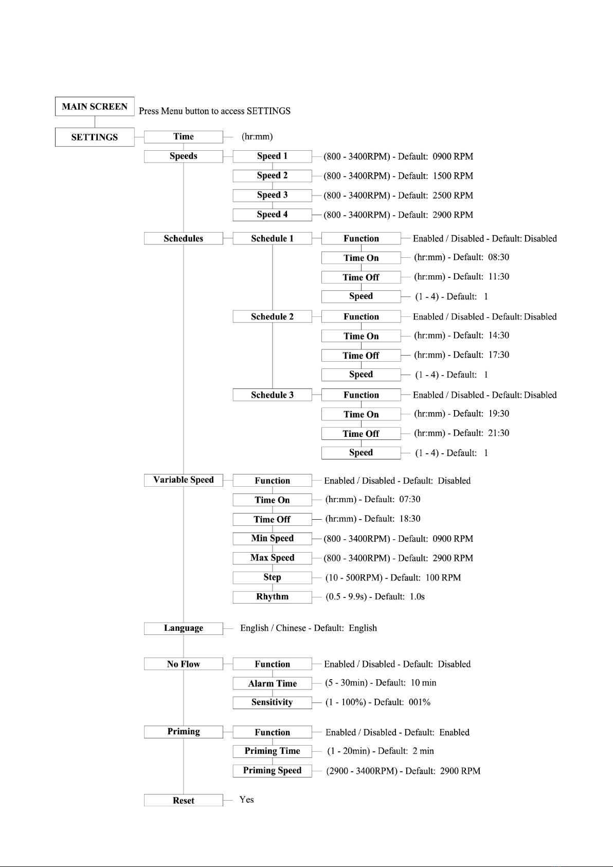
To revise / update "Time On" settings within “Schedules 1” menu:
Use “Up” / “Down” buttons to go to “Time on” option and press “Enter”.
Choose hours / minutes using “Left” / “Right” buttons.
Change hours / minutes using “Up” / “Down” buttons.
Press “Enter” to save settings or “ESC” to cancel.
Press “ESC” to exit.
To revise / update "Time Off" settings within “Schedules 1” menu:
Use “Up” / “Down” buttons to go to “Time off” option and press “Enter”.
Choose hours / minutes using “Left” / “Right” buttons.
Change hours / minutes using “Up” / “Down” buttons.
Press “Enter” to save settings or “ESC” to cancel.
Press “ESC” to exit.
To set up the Schedules 2, 3 & 4 use the same method as for Schedule 1.
2.5.5. VARIABLE SPEED SET UP
This function is set up through the following parameters:
“Function”: Enable / Disable the speed.
“Time On”: Set the start time.
“Time off”: Set the off time.
“Min Speed”: Set the minimum speed (RPM).
“Max Speed”: Set the maximum speed (RPM).
“Step”: Set the speed for different time frames.
“Rhythm”: Set the time frame for water flow to change.
The “Step” & “Rhythm” options are particularly useful for water features like a water descent,
making water flow change and creating a visual effect.
Make sure the pump is in off position before changing the settings.
Press “Menu” to highlight the settings.
Use “Up” / “Down” buttons to go to “Variable Speed” and press “Enter”.
To set up the parameters above use the same method as for Schedule 1.
2.5.6. LANGUAGE SET UP
Make sure the pump is in off position before changing the program.
Use “Up” / “Down” buttons to go to "Language" option and press “Enter”.
The symbol “>” indicates the language in use.
Press “Enter” again to enter in editing mode, use “Up” / “Down” buttons to select the

8
required language.
Press “Enter” to save the setting. The interface will be shown in the selected language
immediately. Otherwise, press “ESC” to exit the editing mode.
Press “ESC” to exit.
2.5.7. “NO FLOW” SET UP
This function is only available for motor speeds of 1800 RPM or more, it is set up through
the following parameters:
“Function”: Enable / Disable “No-Flow” function.
“Alarm time”: Set the time frame for “No-Flow” function. Minimum setting is 5 minutes.
“Sensitivity”: Sensitivity of protection system, expressed in %. Minimum setting is 0.01 %
To set up these parameters use the same method as for Schedule 1.
Fault Code “NF” will be shown if “No Flow” protection is activated.
2.5.8. PUMP PRIMING SET UP
This function is set up through the following parameters:
“Function”: Enable / Disable “Pump Priming” function
“Priming time”: Set the prime time before switching to the other program
“Priming speed”: Set the speed during the priming cycle
To set up these parameters use the same method as for Schedule 1.
Pump Priming Time:
Minimum time:1 minute.
Maximum time: 20 minutes.
Default time: 2 minutes.
Pump Priming Speed:
Minimum speed: 2900 RPM
Maximum speed: 3400 RPM
Default speed: 2900 RPM

9
2.6FACTORY DEFAULT SETTINGS
This option allows you to reset the default factory settings.
2.6.1 INTERNAL MEMORY
If the pump is disconnected from the electrical supply, the programmed default settings will
be maintained for approximately 7 days.
2.6.2 INTERNAL SYSTEM CLOCK
The internal system clock is used to program operating schedules. If the power supply is
disconnected, the controller memory as well as the programmed settings will be maintained
for approximately 7 days. Clock reset up will be required after this time.
2.6.3 INTERNAL SPEED SETTINGS
In order to set speed settings, the pump must be in the off position:
Press “Menu” button.
Use “Up” / “Down” buttons to go to “Speeds” and press “Enter”. The pre-set speeds
from 1 to 4 will be shown.
Use “Up” / “Down” buttons to choose a particular speed (1 – 4).
Adjust the desired speed using “Up” / “Down” buttons.
Press “Enter” to save settings or “ESC” to cancel.

10
2.6.4 PROGRAMMING FLOW CHART

11
3. REPLACEMENT PARTS
Key No.
Part No.
Description
Qty
1
01020016
Nut for Lid
1
2
01041049
Transparent Lid
1
3
02010042
O-Ring for Lid
1
4
01110024
Basket
1
5-7
89020721
2.5’’ Union with O-ring
2
5-7
89020722
2.5’’ Union / 2’’ Tale with O-Ring
2
8
01112087
Pump Body
1
9
89021307
Drain Plug with O-Ring
2
10
02010213
O-Ring
1
11
01110025
Diffuser
1
12
89020719
Screw for Impeller with O-Ring
1
13
01311058
Impeller for EPV150
1
13
01311047
Impeller for EPV200
1
13
01400103
Impeller for EPV300
1
14
04015065
¾’’ Mechanical Seal
1
15
02010212
O-Ring for Flange
1
16
03011402
M3.5 x 35 Screw AISI314
2
17
01020017
Flange
1

12
18
89020720
M8 x 35 Screw with Washer for Motor
6
19
03011075
M8 x 30 Screw
4
20
89023702
Programmable Controller for EPV150
1
20
89023703
Programmable Controller for EPV200
1
20
89023704
Programmable Controller for EPV300
1
21
01321024
Fan Cover
1
22
04020113
EPV150 TYC-80M Motor
1
22
04020114
EPV200TYC-80L Motor
1
22
04020115
EPV300TYC-80XL Motor
1
23
01110026
Base
1
23
02010211
Arch Cushion for Base
1
24
01041054
Transparent Lid for Programmable Controller
1
25
02010302
panel for Programmable Controller
1
26
03039918
Cover for Programmable Controller
1
27
02021080
Cushion for Cover
1
28
04015047
Operation panel (PCB)
1
29
89020802
EPV150PCB with Shell
1
29
89020803
EPV200 PCB with Shell
1
29
89020804
EPV300 PCB with Shell
1
4. DIMENSIONS

13
5. SPECIFICATIONS
Code
Model
Connection
Size
Voltage /
Frequency
Maximum
Input Power
(kW)
Power
(hp)
Weight
(kg)
88021107
EPV150
63 mm / 75
mm
2’’ / 2.5’’
220V-240V
50Hz/60Hz
1,50
1,5
23
88021108
EPV200
1,80
2,0
24
88021109
EPV300
2,20
3,0
25
6. TROUBLESHOOTING
6.1 COMMUNICATION ERROR (COMM ERROR)
If the communication error appears, check the following:
Ensure the 3-pin plug has good contact with the power point.
Reset the system by turning off the power supply, leaving it for 30 seconds and then
switching the pump on again.
If problem persists, contact your Emaux service agent.
6.2 ERROR DISPLAY
When the programmable controller is not working properly, a fault code will be shown on
the controller display.
Error
Description
Possible causes
OC
Overcurrent
Driver's output current exceeds the
threshold (200% of rated current)
Driver output failure
Drive of IPM module is damaged
OV
Overvoltage
Main circuit DC voltage exceeds the
threshold
Excessive power of power supply
Power supply voltage exceeds settings
UV
Undervoltage
The main electric current is too low
Supply voltage fluctuation is too large
OH
Overheating
Heat sink on motor is overheating
Environment temperature is too high
NF
No Water Flow
No water in the circuit
Water level in the pool is too low
Not enough water in the basket when
starting

14
6.3 REPLACEMENT PARTS
Refer all service to your local agent or distributor as his knowledge of your equipment makes
him the best-qualified source of information. Order all spare parts through your distributor.
Please provide the following information when ordering spare parts:
Unit nameplate data or serial number on label.
Description of the part.
6.4 QUICK SOLUTIONS GUIDE
Pump Does Not Start
Power Supply fault, disconnected or defective wiring
Fuses blown or thermal overload open
Locked or Jammed Motor shaft - Contact Service Agent
Motor windings burned out - Contact Service Agent
Pump Does Not Reach Correct Speed
Low Voltage - Contact Service Agent
Motor Overheating
Inadequate ventilation
No or Poor Water Flow
Pump is not primed
Air entering suction piping
Basket full of debris
Inadequate water level in pool
Contact Your Local Service Agent for Further Assistance.
7. SAFETY NOTES
This pump must be equipped with an isolating transformer or through a residual current
device (RCD) having a rated residual operating current not exceeding 30 mA.
If the supply cord is damaged, it must be replaced by the manufacturer or its service agent or
a similarly qualified person in order to avoid a hazard.
This appliance can be used by children aged from 8 years and above and persons with reduced
physical, sensory or mental capabilities or lack of experience and knowledge if they have been
given supervision or instruction concerning use of the appliance in a safe way and understand
the hazards involved. Children shall not play with the appliance. Cleaning and user
maintenance shall not be made by children without supervision.

15
8. WARRANTY POLICY
Emaux manufactures its products with the highest standard of workmanship, using the best materials
available through state of the art process. Emaux proudly warrants its products as follows:
EXTENDED WARRANTY FOR SPECIFIC PRODUCTS
(OFFERED FROM DATE OF INVOICE)
Product
Warranty Period
Filters & Filter Systems
2 years
Pumps
1 year
Underwater Lights
1 year (bulbs 90 days)
Ladders
1 year
Control devices
1 year
Heat Pumps & Heat Exchangers
1 year
Salt Chlorinators & UV Systems
1 year (2 years for cell material)
Pool Fittings
1 year
Cleaning Equipment & All others
1 year
8.1 EXCEPTIONS THAT MAY RESULT IN DENIAL OF A WARRANTY CLAIM
1. Damage caused by careless handling, improper repackaging or shipping.
2. Damage due to misapplication, misuse, abuse or failure to operate and install the
equipment as specified in this manual.
3. Damage caused by a misuse, abuse or failure to operate and install the equipment out of
the scope of a professional level demanded in similar equipment or installation type.
4. Damage due to unauthorized product modifications or failure to use Emaux original
replacement parts.
5. Damage caused by negligence or failure to properly maintain products as specified in this
manual.
6. Damage caused by failure to maintain water chemistry in conformity with the standards of
the swimming pool industry for any length of time.
7. Damage caused by water freezing inside the product.
8. Accident damage, fire, natural disaster or other circumstances outside the control of Emaux.
9. Items repaired or altered in any way by any person that is not authorized by Emaux.
10. Wear & tear parts.
8.2 CLAIM PROCESS
Summary of Emaux Claim Process in 3 steps:
1. Claim: Customer contacts Emaux salesperson and provides complete details of the claim
which includes:
a. Information about the failed product such as the part number(s) and serial number(s).
b. Description of the complaint/failure.
c. Pictures

16
2. Revision: Once the complaint is received, the product quality incident will then be reviewed
by Emaux Quality Department following the “Emaux Warranty Policy”.
3. Conclusion: After the investigation is completed, Emaux will inform the distributor accordingly.
8.3 WARRANTY OBLIGATION
Emaux warrants any of above items from workmanship and/or material(s).
Should a defect become evident during the term of warranty, Emaux will, at its option, repair or
replace such item or part at its own cost and expense. Customer will need to follow the warranty
claim procedures from Emaux in order to obtain the benefit on this warranty.
Emaux is not, however, responsible under this warranty for any cost of shipping or transportation
of the equipment or parts thereof “to” or “from” our technical operations. Emaux is not liable
for any loss of time, inconvenience, incidental expenses such as labor cost, phone calls, legal
cost or material cost incurred in connection with the replacement or removal of the equipment,
or any other consequential or incidental damage on persons or assets. Emaux will be not
responsible for any business profit loss or operation stop due to the non-conformity product
equipment. No indemnity or damages can be claimed on any account whatever.
8.4 WARRANTY OR REPRESENTATIONS BY OTHERS
No dealer or other person has authority to make any warranty or representation concerning
Emaux or its products.
Accordingly, Emaux is not responsible for any such warranty or representation.
9. CORRECT DISPOSAL OF THIS PRODUCT
This marking indicates that this product should not be disposed with other
household wastes throughout the EU. To prevent possible harm to the environment
or human health from uncontrolled waste disposal, recycle it responsibly to promote
the sustainable reuse of material resources. To return your used device, please use
the return and collection systems or contact the retailer where the product was
purchased. They can take this product for environmental safe recycling.
This manual suits for next models
5
Table of contents
Other emaux Swimming Pool Pump manuals
Popular Swimming Pool Pump manuals by other brands

Hayward
Hayward Super Pump VS SP2603VSP owner's manual

CARVIN
CARVIN MAXI Series Operation & installation instructions

IQ
IQ Theratherm Inverter Series User and service manual

Hayward
Hayward TriStar SP322063EEV owner's manual

Hidrotermal
Hidrotermal HIDRO-SPR Series user manual

Pentair Pool Products
Pentair Pool Products Azur 300 installation guide