8
ELECTRICAL
Plug pump into a grounded, GFCI-protected 115 Volt circuit only.
Incorrect voltage can cause fire or seriously damage motor and voids
warranty.
Risk of electrical shock. Connect only to a grounded type re-
ceptacle protected by a ground-fault circuit-interrupter (GFCI).
GFCI tripping indicates an electrical problem. If GFCI trips and will not
reset, have a qualified electrician inspect and repair electrical system.
Risk of electrical shock. Unplug motor before servicing or re-
pairing pump or motor.
Voltage:
Voltage at motor must be not more than 10% above or below motor name-
plate rated voltage or motor may overheat, causing overload tripping and re-
duced component life. If voltage is less than 90% or more than 110% of rated
voltage when motor is running at full load, consult power company.
Grounding:
Pump is supplied with grounded 3-wire cord and plug. Do not modify cord or
plug. Plug into GFCI protected, grounded outlet only.
Wiring:
Table I, Page 4, and Table II, Page 5, give correct circuit breaker sizes for the
pump alone. If other lights or appliances are also on the same circuit, be sure
to add their amp loads to pump amp load before figuring wire and circuit
breaker sizes. (If unsure how to do this or if this is confusing, consult a li-
censed electrician.) Use the load circuit breaker as the master on-off switch.
Plug into a GFCI receptacle on a 115 Volt, 60 Hertz grounded circuit only;
the GFCI will sense a short-circuit to ground and disconnect power before it
becomes dangerous to pool users. For size of GFCI required and test proce-
dures for GFCI, see manufacturer’s instruction.
In case of power outage, check GFCI for tripping (which will prevent normal
pump operation). Reset if necessary.
Do not modify cord, plug or receptacle! If an existing circuit must be used
and the receptacle and factory installed plug do not match exactly, consult a
licensed electrician.
Do not use an extension or drop cord.
Match circuit breaker size to Table I, Page 4, or Table II, Page 5 (depending
on pump model).
OPERATION
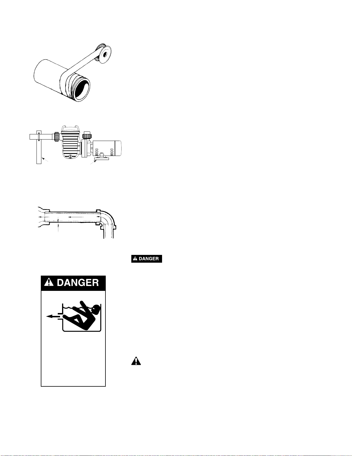
Hazardous suction. Can trap and tear hair or body parts. Can
cause drowning. Small children using pool/spa must ALWAYS have close
adult supervision.
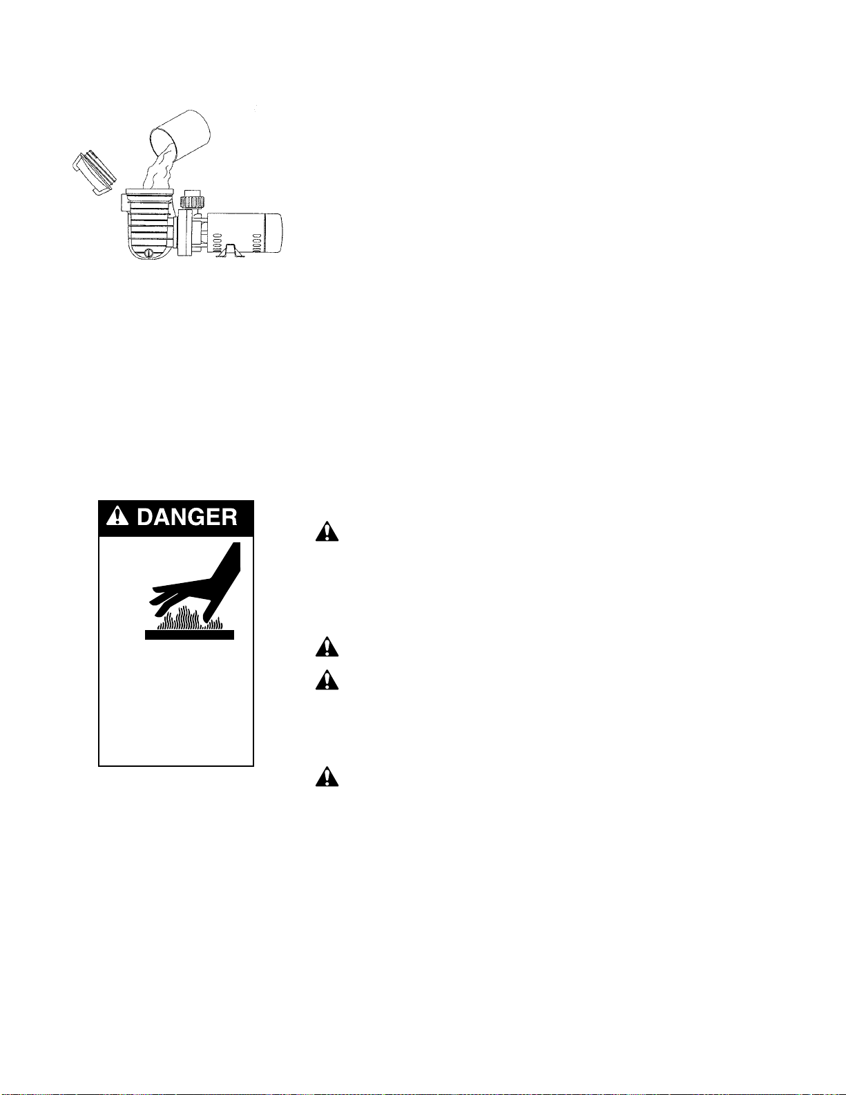
NEVER run pump dry. Running pump dry may damage seals, causing
leakage and flooding. Fill pump with water before starting motor.
Before removing trap cover:
1. STOP PUMP before proceeding.
2. CLOSE GATE VALVES in suction and discharge pipes.
3. RELEASE ALL PRESSURE from pump and piping system.
If pump is being pressure tested, be sure pressure has been released be-
fore removing trap cover.
Priming Pump
Open gate valves before starting system.
Release all air from filter and piping system: see filter owner’s manual.
Hazardous voltage.
Can shock, burn,
or cause death.
Disconnect power
before working
on pump or motor.