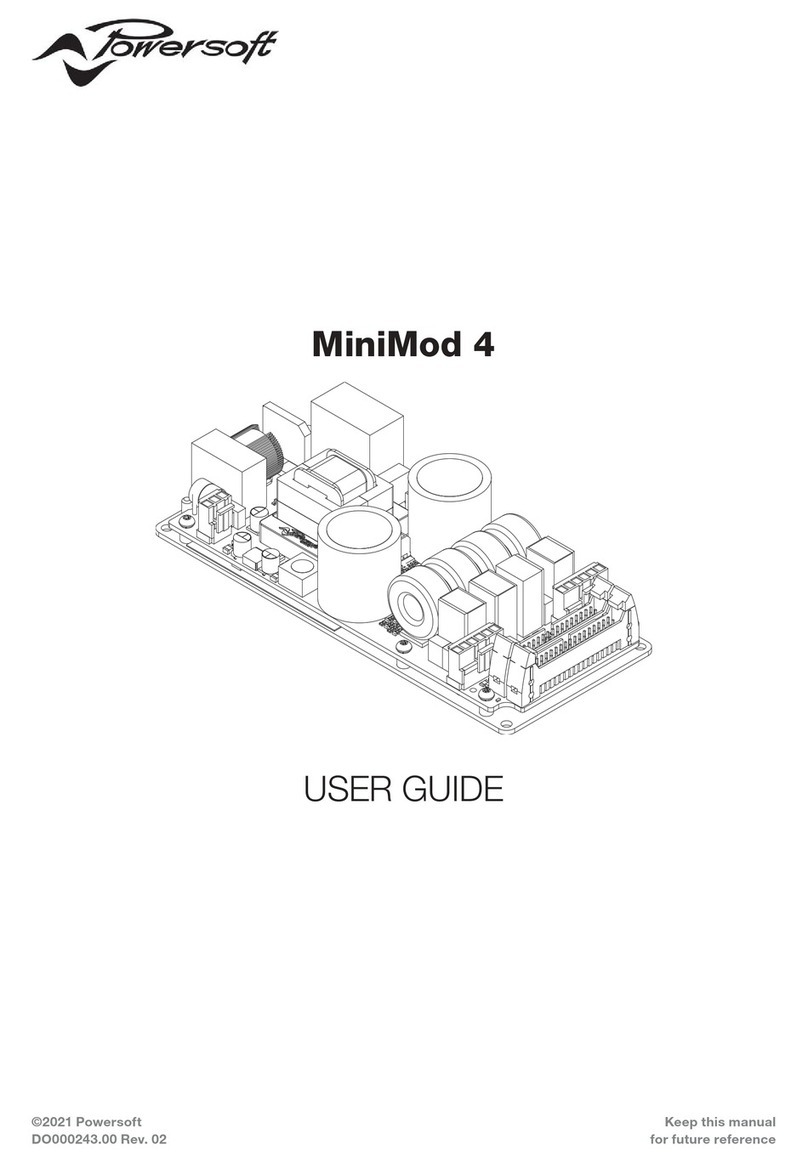
Embedded MyPi Industrial CM4 Integrator Board User manual

Page 1
MyPi Industrial CM4 Integrator Board
User Guide
Issue : 2.1
Dated : June 2023
Prepared By : Andrew O’Connell

Page 2
FEATURES
Supports All Raspberry Pi Compute Module 4 variants
1 x 10/100/1000 LAN
1 x 10/100 LAN
2 x USB 2.0 (external access)
1 x uSD Card Storage (USB Interfaced)
1 x mPCIe Interface (USB Interfaced) + SIM
1 x SPI Infineon SLB9670 TPM 2.0
1 x Battery Backed RTC
1 x Board ID EEPROM (Preprogrammed)
2 x Camera Interfaces
1 x HDMI
1 x Opto-Isolated Digital Input
1 x Modular IO slot with 28 GPIO Pins
o 3 x SPI
o 5 x I2C
o 4 x UART
o SDIO Interfaces
o 3 x GPCLK
o 2 x PWM Channels
1 x Optional 60second watchdog (active from power up/boot)
1 x Temperature activated fan control (same as Pi CMIO4 board)
2 x Bi-colour user LEDs
9-28V Input
Wide -20°C to +80°C Ambient operating temperature

Page 3
BOARD IO FEATURES
❶ ❷ ❸ ❹
❺ ❻ ❼
❽
❽ ❷
❿
⓫
⓬
⓭
⓭
⓮
⓯
⓰ ⓱
⓱
⓱
⓲
⓲
⓳
❼
⓴
❶
Compute Module 4 Socket
❷ mPCIe Socket + Modem SIM Socket
❸ SPI Interfaced SLB9670 TPM 2.0
❹ 60 Second Watchdog + Enable Links
❺ I2C GPIO Expander
❻ I2C Serial EEPROM
❼ I2C EMC2301 Fan Controller
❽ USB µSD Card Interface + Socket
❾ Pi Status LEDs + Mode Links
❿ Dual RPi Camera Sockets
⓫
HDMI Out
⓬ I2C DS1338Z RTC + Coin Cell Backup Battery
⓭ USB LAN9514 10/100 LAN + USB Interface
⓮ 2 x USB 2.0 Ports
⓯ Pi Gigabit 10/100/1000 Interface
⓰ Dual Bi-colour LED
⓱ GPIO IO Card interface + Front Connector
⓲ Power In (9-28V DC)
⓳ Power In Digital Input
⓴ µUSB CM4 Programming port
❾
❹
❹

Page 4
HARDWARE CONFIGURATION LINKS
LED - RESET
This LED indicates when the Pi unit is in reset condition and has asserted an external reset signal,
which is routed to parts 3, 8 & 13
LED - PWR
This GPIO driven LED indicates ‘power’ functionality on a Raspberry Pi and can be repurposed for
general usage, signal also connected the bottom red LED.
LED - ACT
This LED indicates ‘Activity’ functionality on the Pi unit, by default this indicates eMMC flash access
on the module, but can be reassigned to indicate other status signals.
LK1 - Boot Mode
Fitted Forces CM4 module into eMMC programming or EEPROM Firmware update mode
Open Default, boots as normal according to EEPROM settings
LK4 - BT DIS
Fitted Forces CM4 module to disable Bluetooth RF Output
Open Default

Page 5
LK2 - WIFI DIS
Fitted Forces CM4 module to disable WiFi RF Output
Open Default
LK3 - EEPROM DIS
Fitted Indicates to CM4 module to disable EEPROM
(Facility not enabled in firmware by default)
Open Default
LK5 - WD EN
Fitted Connect External Watchdog Enable Line to GPIO16
Open Default
LK7 - WDI
Fitted Connect External Watchdog Input Line to GPIO17
Open Default

Page 6
LK6 - WATCHDOG RESET OUT
Fitted Connect External Watchdog Reset Out to CM4 RUN/RESET Line
Open Default

Page 7
RASPBERRY PI COMPUTE MODULE PROGRAMMING
The unit as shipped is configured to allow the eMMC flash on the compute module to be re-
programmed without removing the PCB from the enclosure.
Units come pre-programmed with the demo Raspbian OS pre-installed, this section describes how to
write a new disk image to the Compute Module.
First of all download the windows USB boot installer, this will install the device drivers as well as a
program we'll use later called RPi-Boot
Raspberry Pi RPI-BOOT Software Download Link
Connect the mini USB connector to the Windows PC using the supplied USB A to micro USB B data
cable, fit the boot mode jumper link (LK1) and then power up the unit.
Windows will then show the following stages as it configures the OS :
Once that sequence has finished Windows has now installed the required drivers and you can power
off the unit for a moment whilst we get the PC side ready for the next step.

Page 8
Making sure you have the unit powered off start up RPi Boot, this is easiest done via the start menu,
we have found this needs to be run as ‘Administrator’ privilege mode for correct operation
When the RPi-Boot starts up it’ll sit and wait for the attached board to boot up :
Power up the unit and RPi-Boot will configure the unit to appear as a flash drive :
When done the compute module will alternate into mass storage mode (so behaving just as though
it's a USB memory stick) and windows will then recognise the module as an external drive.

Page 9
If the compute module eMMC already contains an OS Windows will recognise the FAT partition and
assign that (at least) a drive letter, this is useful in the event that a configuration error with the boot
files is made (e.g. dt-blob.bin or config.txt) and needs recovery actions to be performed.
After drive letter assignment Windows may indicate that partitions need scanning or fixing, these
can be ignored/cancelled.
There are a few different ways we can load on the OS, for simplicity we’ll cover using the
recommended OS writing software and process from the main Raspberry Pi website
This process writes a disk image, containing the partition table as well as both FAT boot partition and
Linux EXT partitions, over the entire disk.
The basic sequence we're following is :
1. Download the Win32DiskImager utility from this Download Link
2. Install and run the Win32DiskImager utility (You will need to run the utility as administrator,
right-click on the shortcut or exe file and select Run as administrator)
3. Select the OS image file you wish to write
4. Select the drive letter of the compute module in the device box (in our case F:) - Again note
that the disk image is a 1:1 of the entire disk (containing the partition table, FAT & EXT
partitions)
Be careful to select the correct drive; if you get the wrong one you can destroy your data
on the computer's hard disk!
5. Click Write and wait for the write to complete

Page 10
CM4 BOOT EEPROM FIRMWARE UPDATE
On the CM4 it is not possible to update the boot firmware EEPROM from the command line
To find the current boot loader version run vcgencmd bootloader_version
For best USB and Camera support we recommend installing version July 6th 2021 or later
To update the firmware on a CM4 device the same rpiboot program is used, but with a different
syntax to usual. This directs the system to push a different set of files to the CM4 device containing
the firmware update files.
Fit the boot mode link and connect up the microUSB programming cable and run rpiboot as shown
in the screenshot below. This process takes a short amount of time and once completed the HDMI
output will indicate a green screen with rapidly blinking status LED to show success.
To change/update the firmware version files of your install replace the ‘recovery’ folder on your
local machine with that of the ‘recovery’ folder from the main github repo below
https://github.com/raspberrypi/usbboot

Page 11
CM4 SECURE BOOT
Secure boot facilities on the CM4 are currently in beta release, see below website link for examples
and notes on how to create a signed boot image
https://github.com/raspberrypi/usbboot#secure-boot---image-creation
See also TPM Hardware Security Module notes following

Page 12
SYSTEM GPIO
In order to minimise CM4 GPIO line usage an I2C interfaced PCA9536 GPIO expander has been
included
These present as gpio500-503 on the OS and are configured via the system device tree overlays :
# I2C Bus (Note : Also need to add i2c-dev to /etc/modules)
dtparam=i2c_arm=on
dtoverlay=pca953x,addr=0x41,pca9536
A bash script /etc/init.d/mypi-init.sh which is called from /etc/rc.local during boot-up which creates
the below symbolic links for quick access in /dev
mpcie-wdisble -> /sys/class/gpio/gpio500/value
mpcie-reset -> /sys/class/gpio/gpio501/value
led2-red -> /sys/class/gpio/gpio502/value
led2-green -> /sys/class/gpio/gpio503/value
led1-red -> /sys/class/leds/led1/brightness
rtc_nvram -> /sys/class/rtc/rtc0/device/nvram
wd-enable -> /sys/class/gpio/gpio16/value
wd-input -> /sys/class/gpio/gpio17/value
Example usage :
$ echo 1 >/dev/led1-red
$ echo 0 >/dev/led1-red
$ echo 1 >/dev/led2-green
$ echo 0 >/dev/led2-green
$ echo 1 >/dev/mpcie-reset
$ echo 0 >/dev/mpcie-reset
# echo ‘battery backed up ram’ > /dev/rtc_nvram
cat /dev/rtc_nvram
battery backed up ram
Board OS Configuration
The sample OS image provided has been produced by overlaying a series of files over a standard
Raspberry Pi Lite OS Image. The configuration files can be downloaded using the tar file linked to
below
https://drive.google.com/file/d/1b8HxL6FkDFo-N_3SfSyCkyBcHYBUnngL/view?usp=sharing

Page 13
USB INTERFACE
There are two critical settings that determine the USB controller active on the CM4, without these
steps the system will either disable the USB port or enable the low bandwidth port controller.
1. Firmware version
This should be version dated July 6th 2021 or later, needed to enable the internal controller
2. Config.txt setting
otg_mode=1 should be included in the configuration file to select the xhci-hcd controller
Correctly setup the system will report the root hub as being an xhci-hcd device as shown below

Page 14
USB SD CARD INTERFACE
The on-board micro SD Card is interfaced to the Raspberry Pi Compute Module using on-board
Microchip USB2240 SD card interface controller, this provides fast access to secondary storage for
datalogging.
configuration file /etc/udev/rules.d/8-sdcard.rules creates the below /dev shortcuts for the main
SD Card and any partitions contained
This SD card cannot be booted from however can be auto mounted at boot (via /etc/fstab) so offers
a low cost method of expanding the core eMMC filesystem
We recommend the use of industrial grade SD cards, which whist more expensive have greater
operating temperature range, on-device wear-levelling and generally greater endurance than
commercial grade parts.
For more information please see our knowledgebase article below
https://embeddedpi.com/documentation/sd-card-interface/raspberry-pi-industrial-micro-sd-cards
A hardware reset of the USB2240 device is asserted at reboot/power up by the Compute Module

Page 15
USB 10/100 LAN + USB CONTROLLER
Integrated on-board is an Microchip LAN9514 device, this is connected to the Raspberry Pi via USB
port and provides 4 additional downstream USB ports, two of which are used for the on-board
mPCIe interface and USB2240 SD Card controller and the remaining two are brought out to the front
face USB ports.
There are two scripts that are helpful:
/usr/local/bin/resetbyauthorized.sh
This script allows you to issue a software reset command to a USB peripheral by supplying the
vendorid & productid identifiers
/usr/local/bin/usbpwrctl.sh
This script allows you to switch the power off/on to either/both of the front USB ports
A hardware reset of the LAN9514 device is asserted at reboot/power up by the Compute Module

Page 16
USB MINI-PCIE INTERFACE
The Integrated mPCIe socket installed on the base board are wired to the below standard :
Signals in RED are not available
The below GPIO connections are made to the connector
mpcie-reset -> /sys/class/gpio/gpio500/value
mpcie-wdisble -> /sys/class/gpio/gpio501/value
The WWAN LED is connected to the front top green bi-colour LED to indicate modem network
registration/data transmission status.

Page 17
Modem Compatibility/Operation
See the below link to pages from the main modem documentation section for details on how to
operate modems :
http://www.embeddedpi.com/documentation/3g-4g-modems
The system has been pre-installed with modem helper status script modemstat which supports
Sierra Wireless, Quectel and Simcom
See web page below for more details
https://embeddedpi.com/documentation/3g-4g-modems/mypi-industrial-raspberry-pi-3g-4g-
modem-status
A number of udev rules have been added to provide consistent shortcut symbolic links for easy
identification of the various ttyUSB interfaces created by the modem. These udev rule files are
contained in the /etc/udev/rules.d/modem-rules folder.
Note that increasingly modems are requiring raw ip connection method to be implemented, to this
end we have added qmi-network-raw in /usr/local/bin which makes this connection type easier
along with udhcp which supports raw ip mode for obtaining an IP address once connection has been
made.

Page 18
QMI Network Connection example :

Page 19
QUECTEL-CM example
Quectel Modems have a utility provided by Quectel to manage the connection process and which
will automatically configure any raw-ip settings
First install the all-in-one quectel-cm connection helper program; this will automatically configure
any raw-ip settings
https://github.com/mypiandrew/quectel-cm/releases/download/V1.6.0.12/quectel-CM.tar.gz
The command has the below syntax
quectel-CM [-s [apn [user password auth]]]
[-p pincode] [-f logfilename] -s [apn [user password auth]]
Example 1: ./quectel-CM
Example 2: ./quectel-CM -s pp.vodafone.co.uk
Example 3: ./quectel-CM -s internet web web 0 -p 1234 -f modemconnect.log
Note that this is a non-exiting process so will not automatically fork and run in the background

Page 20
Sample Connection output, note the fall back to raw-ip is automatic.
Killing the process or issuing Ctrl-C results in the connection to be disconnected and interface
disabled.
