EmberGlo AR30 Troubleshooting guide
Installation Service
Manual & Parts
EmberGlo Model AR30
EmberGlo
A Division of Midco International Inc.
4140 West Victoria Street
Chicago, Illinois 60646
tel 773.604.8700
fax 773.604.4070
web www.emberglo.com
Quality Designed for Proven Performance
PRINTED IN U.S.A.
699
8449-80
CAUTION:
This steamer to be used with distilled water only
(demineralized). Without treated water, deposits can build
up in steam generators causing reduced steam volume and
eventual stoppage of steam production. Clogged or limed
steam generators caused by use of non-distilled water will not
be covered under the terms of the warranty.
Warranty
All electrical equipment sold under the Ember-Glo trademark
is warranted against defects in material and workmanship for
a period of one year from date of original installation. Midco's
obligation under this warranty shall be limited to repairing or
replacing, at our option, any part of said equipment which
Midco's examination shall disclose to its satisfaction to be
thus defective.
Under the terms of this warranty, models considered portable
(devices with cords and plug caps such as Midco Steamers)
must be returned to the nearest service station, transportation
prepaid. Non-portable units with permanent wiring will be
serviced on the customer's premises. Under these terms,
Midco agrees within the terms of this Warranty, to make all
repairs at no charge. Portable units will be returned,
transportation collect.
This warranty does not apply to damages resulting from
accident, misuse, abuse or alteration.
No equipment may be returned without written authorization
from Midco. Returned goods must be shipped prepaid to the
factory.
WARNING: Improper installation and use of this
product could result in personal or property injury.
Warranty card must be filled in and returned to Midco to
validate warranty.
SSAAFFEETTYYIINNFFOORRMMAATTIIOONNTTEERRMMSS::The following terms are
used to identify hazards, safety precautions or special
notations and have standard meanings throughout this
manual. When you see the safety alert symbol and one of the
safety information terms, as shown below, be aware of the
hazard potential.
DANGER: Identifies the most serious hazards which
will result in sever personal injury or death.
WARNING: Signifies hazards that could result in
personal injury or death.
CAUTION: Identifies unsafe practices which would
result in minor personal injury or product and
property damage.

Installation
Operation
Maintenance
Daily as Required
Service
1. Position steamer on level surface and plug power cord into 3-hole 120 volt AC grounded
receptacle. If an adapter is used, it must be grounded properly.
2. Pull out water pan and fill with distilled (NOT HOT OR BOILING) water to 1/4" from the
top of the water pan baffles; then close drawer. Unit is now ready for operation.
1. Move toggle switch to ON position. The pilot light remains on at all times. Allow 15-20
minutes to reach operating temperature.
2. Open food drawer, place food in pan; close drawer and operate lever as required per
cooking guide.
3. At end of time cycle, open drawer and remove food.
4. Keep drawer closed when not in use.
5. To shut off unit move toggle switch to OFF position.
Caution: Operate lever to the left and return to vertical position. Rapid repeated
operation will over steam the unit. The amount of steaming necessary is determined
by the type and amount of food to be heated. For more than one shot, wait 15
seconds between shots. A "shot" is one operation of the lever.
The food pan is removed by lifting up. Clean the inside thoroughly and wipe the outside to
remove any material which might have accumulated.
■■
■■
To remove the food drawer, pull the drawer out until it stops, release stop located at rear
underside of drawer to unlock, and pull out the frame. Wipe the drawer and frame clean and
return by inserting the drawer slide into the slide of the frame, then push the food pan to the
rear until the lock engages automatically.
Note: Before attempting service, unplug power cord.
For service or examination, all "working parts" of the steamer are exposed by removing first
the cabinet top, then the back. The wiring diagram and spare cleanout gasket is located on
inside of back.
Electric Switch/Thermostat
The on-off switch should audibly "click" when operated manually. To determine if electrically
operative, a continuity check should be made.
■■
■■The thermostat is factory calibrated and non-adjustable and should no be repaired. Replace
if defective.
Pump System
Operate pump lever and observe length of pump shaft travel. It should travel approximately
5/8". If travel is less, check for broken or disengaged pins, links, crank or half moon key.
■■
■■Disconnect brass fitting at water riser tube and bend tube up slightly so discharging water
will clear front of unit. Operate pump lever; water should shoot out about 15 feet. If water
does not shoot out, remove and inspect inlet tube assembly for leaks. Any air entering tube
will break the suction on the water. Check installation and alignment of dip tube spring as
detailed under next section. If water still doesn't not shoot out, pump should be replaced.
■■
■■A strainer is located in the inlet tube at pump fitting. Loosen fitting and remove pump inlet
tube. Dump strainer out of tube and wash under running water, then replace.
Dip Tube and Spring
If the dip tube does not enter the water pan properly it must be replaced. When replacing, the
open end or point of hook must be at the bottom and the eye must be in a vertical plane, like
a coin standing on edge.
Installation and Service
2

Service
Continued
Trouble
Chart
Steam Generator
1. To Clean. Remove cabinet top and generator insulation. This will expose a square plate
on the generator, which is removable for cleaning water passages.
■■
■■
Check the three exposed holes when the clean-out cover is removed. If any of these
holes are clogged, clean them out by hand-twisting a 7/64" drill for the center hole and a
3/16" drill for the two side holes.
■■
■■
After thoroughly cleaning the three holes, plug in power supply and operate lever to
steam unit. THE UNIT MUST BE HOT. Operate several times to blow out any
accumulation.
■■
■■
Replace the clean out cover, using new gasket. With the unit hot, operate lever. The
unit should steam properly. If it does not, and the pump is operative as detailed under
PUMP SYSTEM, the entire generator assembly is probably limed and must be
disassembled and cleaned or replaced.
■■
■■To clean generator assembly, separate casting from plate and clean lime from cavity in
casting.
Caution: Do not damage plate by scratching or polishing the finish.
2. To Remove.
■■
■■Disconnect the water riser tube.
■■
■■Disconnect electric wiring at the two terminals.
■■
■■Remove 16 hex nuts. Note: Remove food drawer and hold screws up to prevent
turning.
■■
■■Lift off generator.
3. To Replace. Place flat plate on steamer housing so the 12 steam holes line up. Lay a
bead of Dow-Corning 732 or General Electric 159 RTV Silicone adhesive (available at
hardware stores) around large cavity in casting. The bead should be about 1/16" to 1/8"
(diameter) and approximately 1/8" from edge of cavity. Use finger to smooth out the
silicone, be careful not to block steam holes.
■■
■■Place casting on plate, replace screws and tighten securely. Allow the RTV to set about
24 hours before operating unit.
Note: Also refer to TroubleShooting Guide (8471-03) for addition service information.
1. Unit will not heat up; light out.
a. No power.
b. Plug out.
c. Loose internal connection.
d. Defective switch.
2. Unit will not heat up; light on.
a. Defective thermostat.
b. Loose heating element connection.
c. Defective generator electrical unit.
3. Unit heats up light will not light.
a. Defective light in switch.
b. Loose connection.
4. Unit heats up; does not steam.
a. No water in pan.
b. Defective pump.
c. Cam, pins or linkage broken or disengaged.
d. Leak in inlet tube.
e. Dip tube spring assembly misaligned.
f. Clogged steam generator.
Note: If electrical trouble is other than loose connections, it is recommended that parts be
replaced rather than repaired.
3

PART NUMBER DESCRIPTION
1 1402-00 Spec Label
2 1694-00 Caution Label
3 2618-00 Cord Set
4 2619-30 Water Pan Baffle (2-Required)
5 2625-30 Pump Spring
6 5601-40 Generator Insulation
7 5601-80 Clean Out Cover Gasket
8 5601-90 Clean Out Cover
9 5604-35 Dip Tube Spring Assembly
10 5604-83 Spacer
11 5605-20 Cam Pin (2-required)
12 5607-00 Slide Channel Rivetment
13 5608-50 Food Pan Grid
14 5609-00 Water Pan Weldment
15 5613-00 Cabinet Top
16 5615-02 Pump Handle
17 5616-90 Strain Relief
18 5622-00 Steam Range Name Plate
19 5626-00 Food Pan
20 5648-00 Pilot Light Assembly
21 2608-10 Discharge Plate
22 5655-00 120V Generator
23 5658-00 Steam Chamber Weldment
24 5658-60 Steam Chamber Bottom Rivetment
25 5658-80 Food Drawer Rivetment
26 5659-20 Door Liner/Cusset Weldment
27 5659-60 Crank
28 5659-90 Rear Leg
29 5660-00 Pump/Check Valves
30 5660-10 Pump Chassis Weldment
31 5660-50 Cabinet Back
32 5660-60 Upper Switch Panel
33 5660-70 Food Door
34 5660-80 Left Cabinet Side
35 5660-81 Right Cabinet Side
36 5660-90 Riser Tube
37 5661-05 Pump Tube Assembly
38 5661-30 Bulb Clamp
39 5661-40 Heyco Mount
40 5661-50 Upper Switch Panel Spacer
41 5661-60 Spring Anchor
42 5661-70 Left Water Pan Support
43 5661-71 Right Water Pan Support
44 5661-80 Rear Foot (2-Required)
45 5661-90 Steam Deflector
46 5663-00 Pump Rod End
47 5663-10 Slide Channel Stop
48 5663-20 Pump Line (2-Required)
49 5663-90 Food Drawer Nut Plate (2-Required)
50 8423-14 Rocker Switch
51 8452-08 Thermostat
52 8445-00 Ball Knob
53 8445-01 Cover Knob
54 8445-04 Black Vinyl Grip
55 8450-11 3/32 x 5/8Woodruff Key
PART NUMBER DESCRIPTION
56 8450-19 3/8Nyliner
57 8450-25 Socket Tip (4-Required)
58 8451-36 10-24 x 1/2Stainless Steel Carriage Bolt (16-Required)
59 8451-44 Strainer
60 8480-17 74B Wire Nut (2-Required)
61 8483-00 1/8M x 1/4T Compression El
62 8496-11 1/8Brass Pipe Fitting
101 6-32 x 1/8Slotted Round Head Zinc Plated (2-Required)
102 6-32 x 1 Slotted Oval Head Nickel Plated (2-Required)
103 6-32 Hex Nut Zinc Plated (2-Required)
104 No. 6 Split Lockwasher Stainless Steel (2-Required)
105 No. 8 x 3/8Phillips Round Washer Head (13-Required)
106 10-24 x 3/8Slotted Round Head Stainless Steel (13-Required)
107 10-32 x 1/4Slotted Pan Head Stainless Steel (2-Required)
108 10-24 Hex Nut Zinc Plated (23-Required)
109 No. 10 Flat Washer Zinc Plated (16-Required)
110 10-24 x 7/8Slotted Round Head Stainless Steel (2-Required)
111 No. 10 Split Lockwasher Stainless Steel (16-Required)
112 10-24 x 1/4Slotted Pan Head Stainless Steel
113 10-32 x 3/8Phillips Truss Head Stainless Steel (4-Required)
114 1/4-20 Hex Nut Zinc Plated
115 1/4Split Lockwasher Zinc Plated
116 1/8x 1 Cotter Pin Zinc Plated
117 Hitch Pin (2-Required)
118 3/32 x 3/16 Aluminum Pop Rivet (2-Required)
119 Black Switch Tip
120 1/2-20 Pal Nut 1220 Zinc Plated
121 Celsidot 450°F Label
122 5/16-24 Hex Jam Nut
The Following Kits Are Available
2608-80 (16) 8451-36 Stainless Steel Carriage Bolts
with nuts and washers
5604-35 (1) 5604-30 Dip Tube Spring Assembly with nut
5605-90 (2) 5605-20 Cam Pin with (2) hitch pins
5609-50 (2) 2619-30 Water Pan Baffles
5615-10 (1) 5615-02 Pump Handle with 8450-19 Nyliner,
8450-11 Woodruff Key and 1/8x 1 cotter pin
5627-20 (1) 5601-90 Clean Out Cover, (2) 5602-20 Clean Out
Cover Gasket with (2) 10-24 x 3/8slotted round head
screws, (2) No. 10 split lockwashers and Celsidot label
5659-65 (1) 5659-60 Crank with 1/8x 1 cotter pin and (1)
8450-11 Woodruff Key (order part no. 5605-20 cam
pins and hitch pins separately)
5661-05 (1) 5661-00 Pump Tube Assembly with 5/16 nut and
ferrule
5663-25 (2) 5663-20 Pump Links only
5663-50 (1) 5660-00 Pump/Check Valves (1) 5560-10 Pump
Chassis Weldment (1) 5659-60 Crank (2) 5663-20
Pump links (3) 5605-20 Cam Pins (1) 5663-00 Pump
Rod End (2) hitch pins (1) 1/4-20 hex nut (1) 1/4split
lockwasher and (1) 5/16-24 hex nut
5663-60 (1) 8543-13 Wire Assembly Black (1) 8543-14 Wire
Assembly Black (1) 8551-17 Wire Set White and (1)
8551-18 Wire Set Black
5663-70 (1) 5660-90 Riser Tube with (2) each tube sleeves and
tube nuts
Parts
Avoid error in parts selection. When ordering, use complete Ember-Glo part number and description. Furnish model number,
bill of material number and date code or serial number from specification plate.
IMPORTANT: Availability of parts as well as specifications are subject to change without notice.
Please consult factory for item availability.
4
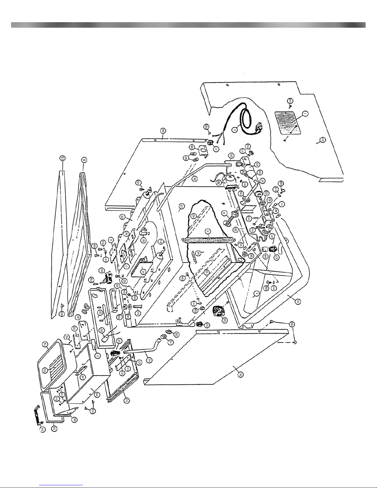
Exploded View
120V 12.5A 1500W
5

Heating and Cooking Guide
These suggestions are made only to help the operator get started. Since each location will
have different portions and different requirements, each operator must determine his own
operation habits. Please remember that the steamer conserves its steam in the drawer and
therefore does not often need repeated shots. The main exception is when frozen product
must be defrosted.
If a product is at room temperature or refrigerated, start with 2 shots (operate lever
twice). This ensures that the food pan is full of steam.
If a product is frozen, start with 3 shots because condensation on the cold product
eliminates the steam quickly.
Cooking Instructions
Meats
Sliced meats
Hamburger patties (precooked)
Cheeseburger (precooked)
patty with cheese
patty with cheese on bottom bun
Hot Dogs
Bacon (precooked)
Link Sausage (precooked)
1/2Chicken (1lb)
Ribs (precooked)
Poached
Soft Boiled
Buns (open)
Buns (closed)
Rolls
Macaroni and Cheese (casserole)
Rice (precooked)
Spaghetti (precooked)
Vegetables (precooked)
Chop Suey (casserole)
Shrimp (unfrozen)
2
2
2
2
2
2
2
2
2
1
2
2
3
2
2
2
3
3
10-20
30
30
90
60-90
45
60
60
30
10
20
20
90-120
45-60
45-60
30-45
90-120
90
Shots Seconds
Eggs
Bread
Pasta
2 shots/60 sec. then
2 shots/30 sec.
2 shots/60 sec. then
2 shots/90 sec.
Excellent results can also be achieved with many other precooked or frozen foods such as any
non-breaded seafood… clams… lobster tails… scallops… red snapper… crab legs… all breads
and rolls… french bread loaves… hoagies… onion buns… many specialty foods… tortillas…
enchiladas… pizza slices… and much more!
6
Other manuals for AR30
2
Table of contents
Other EmberGlo Electric Steamer manuals


