Embest BB-EPH1800 User manual

BB-EPH1800
User Manual
Version 1.0–March 2016

Embest Technology
Copyright ©2016 Embest Technology BB-EPH1800 User Manual
i
Copyright Statement:
BB-EPH1800 and its related intellectual property are owned by Shenzhen
Embest Technology Co., Ltd.
Shenzhen Embest Technology has the copyright of this document and reserves
all rights.Any part of the document should not be modified, distributed or
duplicated in any approach and form with the written permission issued by
Embest Technology Co., Ltd.
Disclaimer:
Shenzhen Embest Technology does not take warranty of any kind, either
expressed or implied, as to the program source code, software and documents in
the CD/DVD-ROMs provided along with the products, and including, but not
limited to, warranties of fitness for a particular purpose; The entire risk as to the
quality or performance of the program is with the user of products.
Revision History:
Version
Date
Description
1.0
2015-12-25

Embest Technology
Copyright ©2016 Embest Technology BB-EPH1800 User Manual
ii
Table of Contents
Chapter 1 Product Overview..........................................................................................1
1.1 Brief Introduction............................................................................................1
1.1.1 Packing List............................................................................................1
1.1.2 Product Features ...................................................................................2
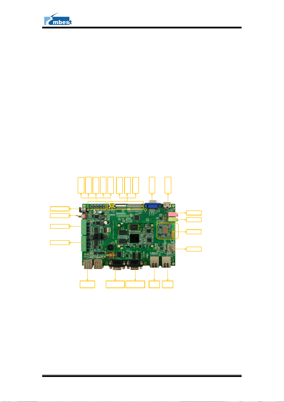
1.2 Interfaces & Buttons.......................................................................................3
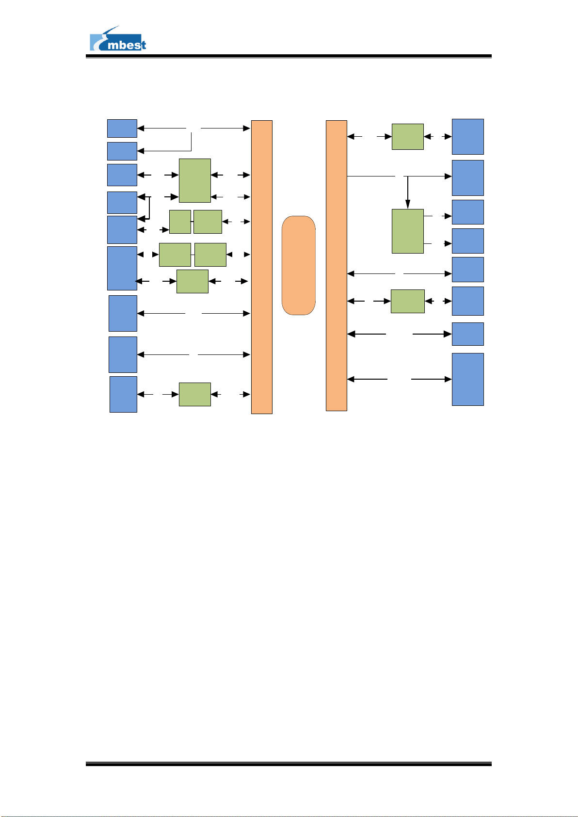
1.3 System Block Diagram...................................................................................4
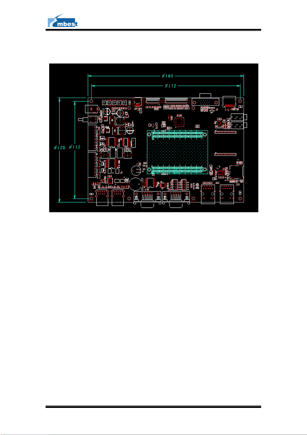
1.4 Product Dimensions(mm)..............................................................................5
Chapter 2 ............................................................................................................................6
Introduction to Hardware System....................................................................................6
2.1 Overview of CPU ...........................................................................................6
2.2 Introduction to Peripheral Chips ....................................................................6
2.2.1 CH7033..................................................................................................6
2.2.2 AR8035..................................................................................................7
2.3 Details of Interfaces.......................................................................................7
2.3.1 PH180 Interfaces ................................................................................7
2.3.2 LCD/VGA/HDMI...................................................................................15
2.3.3 CAMERA..............................................................................................18
2.3.4 Gigabit Ethernet...................................................................................19
2.3.5 TF Card................................................................................................20
2.3.6 USB & HUB..........................................................................................21
2.3.7 Wifi.......................................................................................................22
2.3.8 UART&RS485&CAN............................................................................23
2.3.9 Button...................................................................................................23
2.3.10 UART .................................................................................................23
2.3.11 LED ....................................................................................................24
2.3.12 RTC....................................................................................................24
2.3.13 External Button ..................................................................................24
Technical Support and Warranty....................................................................................25

Embest Technology
Copyright ©2016 Embest Technology BB-EPH1800 User Manual
1
Chapter 1 Product Overview
1.1 Brief Introduction
BB-EPH1800 is an evaluation base board designed by Embest for PH180 related SOM
modules for areas such as medical instruments, video surveillance and industrial control.
BB-EPH1800 provide lots of external interface for PH8700/PH8800, and has 4 high-speed
USB2.0 Host interfaces,a OTG interface, a TF card slot for mass storage, a 12-bit camera
interface, a VGA interface, 2 Gigabit Ethernet, a 24-bit LCD interface, WIFI, Mic input,
Audio output, Uart,Can,Rs485 and so on. Meanwhile, it has two 5Pin on-board DIP
switches include UART, I2C, SPI used to do the function extension.
1.1.1 Packing List
SOM-PH8700/SOM-PH8800 Core Board X1( one of two )
BB-EPH1800 Evaluation Board X1
WIFI Module X 1 (optional)
12V 2A DC Power Adapter X1
8GB TF card X1
4.3 inch LCD or 7 inch LCD Panel X1(optional)
HDMI Connection Cable X1
Uart Connection Cable X1
USB OTG Connection Cable X1
Ethernet Connection Cable X1

Embest Technology
Copyright ©2016 Embest Technology BB-EPH1800 User Manual
2
1.1.2 Product Features
General Specifications:
Operating Temperature:0~70℃
Power Supply:9~25V
Operating Humidity:20% ~ 90%
Dimensions:180 mm×120 mm
PCB Layers:4Layers
Data Transfer Interfaces:
A DB9 RS232 Uart
A 12 bit Digital Camera
Two Gigabit Ethernet(RJ45)
Three RS485
Two CAN
Four high-speed USB2.0 Host interfaces
A USB OTG
A TF Card
A Wifi Module
2 个10 Pin External Interface(I2C.UART.SPI and so on )
Debugging Interfaces
Support UART serial debugging
Audio/Video Interfaces:
A 24-bit true-color LCD interface (supporting 4-wire touchscreen)
A VGA interface
A HDMI interface
A MIC Input
Audio Headphone Output

Embest Technology
Copyright ©2016 Embest Technology BB-EPH1800 User Manual
3
Other Interfaces & Buttons
A Power Jack (12V round DC power jack )
A Power Reset Button,A System ResetButton,A BOOTButton and 2
Buttons by customs.
A RTC
1.2 Interfaces & Buttons
System Reset
Power Reset
BOOT
MENU
BACK
USB OTG
CAMERA
LCD
VGA
HDMI
Power In
Power switch
UART RS485*2
RS485 CAN
USB
HOST *4
UART
(Communication)
UART
(debug)
1000M
ETH A
1000M
ETH B
MIC IN
Headphone
Wi-Fi
TF card
Attention
:
the Uart(Communication) and the Uart (output from the Green Jack)share the
same uart ,Don’t use them at the same time.
Figure 1 Interfaces&Buttons

Embest Technology
Copyright ©2016 Embest Technology BB-EPH1800 User Manual
4
1.3 System Block Diagram
SOM-
PH8700/P
H8800
CN1 CN2
TF Card
SD Card
MAX3232
DB9
CONN FOR
DEBUG
SC161IS7
621
ADM
2483
PHONIX
CONN
ADUM120
1
TJA1040T
ADM2483
PHONIX
CONN
FPC 30P
FPC 50P
RJ45-A
RJ45-B AR8035
VGA
CONN
HDMI
CONN
MMC0
SPI0
RS485
x2
CAN CAN0
MDI
MDI
DSS
CH7033
HDMI
RGB
MINI USB
CONN
USB-A X4
CONN
USB2514
3.5MM x2
CONN
WM8904 AnaMcASP
WIFI
MODULE
PIN
Header
GPIO/MISC
GEMAC1
USB
USB USB
RS232 UART0
RS232 UATR4
Camera
UART2RS485
DB9
CONN
MMC/UART1
Figure 2 BB-EPH1800 System Block Diagram

Embest Technology
Copyright ©2016 Embest Technology BB-EPH1800 User Manual
5
1.4 Product Dimensions(mm)
Figure 3 Product Dimensions

Embest Technology
Copyright ©2016 Embest Technology BB-EPH1800 User Manual
6
Chapter 2
Introduction to Hardware System
This chapter will introduce in detail the structure, expansion and peripheral interfaces of
BB-EPH1800 hardware system.
。
2.1 Overview of CPU
BB-EPH1800 is the base board for SOM-PH8700/PH8800 Designed by Embest.That
make a whole show of the AM335X/AM437X Soc feature,The customs can free
replace each other with SOM-PH8700/PH8800 ,Provide a perfect solution for the
resource extension.
。
2.2 Introduction to Peripheral Chips
2.2.1 CH7033
CH7033B is a video encoder designed to drive high-resolution displays through HDMI,
DVI, YPbPr and VGA interfaces. It is suited for mobile Internet devices, laptops, tablet
computers, portable e-books and smart phones.
This chip possesses advanced scaling engine that supports 1080P HDTV. The integrated
frequency shifting engine can provide 60fps under 1080p mode. Additionally, CH7033B
supports SPDIF and IIS digital audio input.

Embest Technology
Copyright ©2016 Embest Technology BB-EPH1800 User Manual
7
2.2.2 AR8035
AR8035 is a low-power and low-cost Ethernet PHY chip and integrated with a
10/100/1000Mb transceiver. It is a single-port tri-speed Ethernet PHY and supports
MAC.TM RGMII interfaces.
AR8035 is compliant with the IEEE 802.3az Energy Efficiency Ethernet Standard and the
Atheros’s proprietary SmartEEE standard, which allows traditional MAC/SoC devices
incompatible with 802.3az to function as a complete 802.3az system.
2.3 Details of Interfaces
This section will introduce in detail the constructions, principles, interface definitions and
considerations of use of peripherals , so that users may have a deep understanding of the
hardware circuitry of the board.
2.3.1 PH180 Interfaces
BB-EPH1800 connect with the core board with the PH180 Interfaces defined by
Embest.
P1,P2 interfaces defined as below
PIN-OUT for P2
Pin
Signal Name
Function
Signal Description
Pin
1
VRTC
PWR
CTL
PWRON_RESETn
2
3
MMC0_DAT0
WARM_RESETn
4
5
MMC0_DAT1
SD/MMC
MMC0_CMD
6
7
MMC0_DAT2
MMC0_CD
8
9
MMC0_DAT3
MMC0_CLK
10
11
GND1
GND
SPI0_CS0
12

Embest Technology
Copyright ©2016 Embest Technology BB-EPH1800 User Manual
8
13
SPI0_SCLK
SPI
SPI0_D1
14
15
SPI0_D0
UART2_RXD
16
17
UART0_RXD
UART
UART2_TXD
18
19
UART0_TXD
UART2_RTS
20
21
UART3_RXD
UART2_CTS
22
23
UART3_TXD
UART1_RXD
24
25
CAN0_RX
CAN
UART1_TXD
26
27
CAN0_TX
UART1_RTS
28
29
I2C0_SDA
I2C
UART1_CTS
30
31
I2C0_SCL
GND
GND3
32
33
GND2
GND
CAM_D1
34
35
CAM_D0
CSI
CAM_D3
36
37
CAM_D2
CAM_D5
38
39
CAM_D4
CAM_D7
40
41
CAM_D6
CAM_D9
42
43
CAM_D8
CAM_D10
44
45
GND4
GND
CAM_D11
46
47
CAM_FIELD
GND
GND5
48
49
CAM_WEN
CAM_PCLK
50
51
GBE_GREEN
GND
GND6
52
53
GBE_YELLOW
CAM_HD
54
55
GND8
GND
CAM_VD
56
57
GBE_TRP2
GND
GND7
58
59
GBE_TRN2
ETH
GBE_TRP0
60
61
GBE_TRP3
GBE_TRN0
62
63
GBE_TRN3
GBE_TRP1
64
65
GND9
GND
GBE_TRN1
66
67
USB0_DM
GND
GND10
68
69
USB0_DP
GBE_MDC
70
71
GND11
GND
GBE_MDIO
72
73
USB1_DM
USB
USB0_ID
74
75
USB1_DP
USB0_VBUS
76
77
GND12
GND
USB1_VBUS
78
79
SPI1_SCLK
SPI
CTL
LCD_PWM
80
81
SPI1_D0
BOOT0_SEL
82
83
SPI1_D1
BOOT1_SEL
84
85
SPI1_CS0
BOOT2_SEL
86
87
GND13
GND
GND14
88
89
5V_VDD1
PWR
5V_VDD2
90
PIN-OUT for P1
Pin
Signal Name
Function
Signal Name
Pin
1
WAKE_UP
CTL
PWR_GOOD
2

Embest Technology
Copyright ©2016 Embest Technology BB-EPH1800 User Manual
9
3
MCASP0_AHCLKX
RESET_OUTn
4
5
MCASP0_FSX
I2S
MCASP0_ACLKX
6
7
MCASP0_AHCLKR
MCASP0_ACLKR
8
9
MCASP0_FSR
MCASP0_AXR0
10
11
VDDA_ADC
MCASP0_AXR1
12
13
ADC0
ADC
ADC1
14
15
ADC2
ADC3
16
17
GNDA_ADC
HDMI_CEC/ADC4
18
19
HDMI_HPD/ADC5
HDMI_TX2-/ADC6
20
21
HDMI_DSCL/IO1
HDMI_TX2+/ADC7
22
23
HDMI_DSDA/IO2
GND
GND2
24
25
HDMI_TX1-/IO3
HDMI/GPIO
HDMI_TXC-/IO7
26
27
HDMI_TX1+/IO4
HDMI_TXC+/IO8
28
29
HDMI_TX0-/IO5
GND
GND3
30
31
HDMI_TX0+/IO6
LCD_D11
32
33
GND4
GND
LCD_D12
34
35
LCD_D0
LCD_D13
36
37
LCD_D1
LCD_D14
38
39
LCD_D2
LCD_D15
40
41
LCD_D3
GND
GND6
42
43
LCD_D4
LCD
LCD_DE
44
45
LCD_D5
LCD_D16
46
47
LCD_D6
LCD_D17
48
49
LCD_D7
LCD_D18
50
51
LCD_D8
LCD_D19
52
53
LCD_D9
LCD_D20
54
55
LCD_D10
LCD_D21
56
57
LCD_HSYNC
LCD_D22
58
59
LCD_VSYNC
LCD_D23
60
61
GND5
GND
CAN
CAN1_RX
62
63
LCD_PCLK
CAN1_TX
64
65
GND7
GND
I2C
I2C_SCL
66
67
IO1/ETH_TXEN
I2C_SDA
68
69
IO2/ETH_RXDV
GPIO/ETH
IO3/ETH_TXD3
70
71
IO4/ETH_TXD2
IO5/ETH_TXD1
72
73
IO6/ETH_TXD0
IO7/ETH_TXCK
74
75
IO8/ETH_RXCK
IO9/ETH_RXD3
76
77
IO10/ETH_RXD2
IO11/ETH_RXD1
78
79
IO12/ETH_RXD0
RVD1/MMC2_CLK
80
81
RVD2/MMC2_CMD
RVD/MMC
RVD3/MMC2_D0
82
83
RVD4/MMC2_D1
RVD5/MMC2_D2
84
85
RVD6/MMC2_D3
RVD7/MMC2_D4
86
87
RVD5/MMC2_D5
RVD9/MMC2_D6
88

Embest Technology
Copyright ©2016 Embest Technology BB-EPH1800 User Manual
10
89
GND8
GND
GND9
90
P1,P2 Signal Description as below
P2 For
BB-
EPH18
00
Pin
Signal Name
INPUT/OUTP
UT
ACTIV
E H/L
Pow
er
level
Description
1
VRTC
O
3.3V
POWER 3.3V
2
PWRON_RESE
Tn
O
L
3.3V
POWER_RESET
3
MMC0_DAT0
I/O
3.3V
MMC0
4
WARM_RESET
n
O
L
3.3V
RESET
5
MMC0_DAT1
I/O
3.3V
MMC0
6
MMC0_CMD
I
3.3V
MMC0
7
MMC0_DAT2
I/O
3.3V
MMC0
8
MMC0_CD
O
3.3V
MMC0
9
MMC0_DAT3
I/O
3.3V
MMC0
10
MMC0_CLK
I
3.3V
MMC0
11
GND1
G
0V
GND
12
SPI0_CS0
I
3.3V
SPI0
13
SPI0_SCLK
I
3.3V
SPI0
14
SPI0_D1
O
3.3V
SPI0
15
SPI0_D0
I
3.3V
SPI0
16
UART2_RXD
I
3.3V
UART2
17
UART0_RXD
O
3.3V
UART0
18
UART2_TXD
O
3.3V
UART2
19
UART0_TXD
I
3.3V
UART0
20
UART2_RTS
I
3.3V
UART2
21
UART3_RXD
O
3.3V
UART3
22
UART2_CTS
O
3.3V
UART2
23
UART3_TXD
I
3.3V
UART3
24
UART1_RXD
I
3.3V
UART1
25
CAN0_RX
O
3.3V
CAN0_UART
26
UART1_TXD
O
3.3V
UART1
27
CAN0_TX
I
3.3V
CAN0_UART
28
UART1_RTS
I
3.3V
UART1
29
I2C0_SDA
I/O
3.3V
I2C0

Embest Technology
Copyright ©2016 Embest Technology BB-EPH1800 User Manual
11
30
UART1_CTS
O
3.3V
UART1
31
I2C0_SCL
I
3.3V
I2C0
32
GND3
G
0V
GND
33
GND2
G
0V
GND
34
CAM_D1
O
3.3V
CAM
35
CAM_D0
I
3.3V
CAM
36
CAM_D3
O
3.3V
CAM
37
CAM_D2
I
3.3V
CAM
38
CAM_D5
O
3.3V
CAM
39
CAM_D4
I
3.3V
CAM
40
CAM_D7
O
3.3V
CAM
41
CAM_D6
I
3.3V
CAM
42
CAM_D9
O
3.3V
CAM
43
CAM_D8
I
3.3V
CAM
44
CAM_D10
O
3.3V
CAM
45
GND4
G
0V
GND
46
CAM_D11
O
3.3V
CAM
47
CAM_FIELD
O
3.3V
CAM
48
GND5
G
0V
CAM
49
CAM_WEN
O
3.3V
CAM
50
CAM_PCLK
O
3.3V
CAM
51
GBE_GREEN
I
L
3.3V
MIIA_LED_LINK
52
GND6
G
0V
GND
53
GBE_YELLOW
I
L
3.3V
MIIA_LED_ACT
54
CAM_HD
O
3.3V
CAM
55
GND8
G
0V
GND
56
CAM_VD
O
3.3V
CAM
57
GBE_TRP2
O
GBE Data
58
GND7
G
0V
GND
59
GBE_TRN2
O
GBE Data
60
GBE_TRP0
I
GBE Data
61
GBE_TRP3
O
GBE Data
62
GBE_TRN0
I
GBE Data
63
GBE_TRN3
O
GBE Data
64
GBE_TRP1
I
GBE Data
65
GND9
G
0V
GND
66
GBE_TRN1
I
GBE Data
67
USB0_DM
USB0
68
GND10
G
0V
GND
69
USB0_DP
USB0
70
GBE_MDC
I
3.3V
MDIO Clk
71
GND11
G
0V
GND
72
GBE_MDIO
I/O
3.3V
MDIO DATA

Embest Technology
Copyright ©2016 Embest Technology BB-EPH1800 User Manual
12
73
USB1_DM
USB1
74
USB0_ID
O
USB0
75
USB1_DP
USB1
76
USB0_VBUS
I
5V
POWER 5V for USB0
77
GND12
G
0V
GND
78
USB1_VBUS
I
5V
POWER 5V for USB0
79
SPI1_SCLK
I
3.3V
SPI1
80
LCD_PWM
I
3.3V
PWM for LCD
81
SPI1_D0
I
3.3V
SPI1
82
BOOT0_SEL
O
3.3V
BOOT0
83
SPI1_D1
O
3.3V
SPI1
84
BOOT1_SEL
O
3.3V
BOOT1
85
SPI1_CS0
I
3.3V
SPI1
86
BOOT2_SEL
O
3.3V
BOOT2
87
GND13
G
0V
GND
88
GND14
G
0V
GND
89
5V_VDD1
O
5V
POWER 5v for core board
90
5V_VDD2
O
5V
POWER 5v for core board
P1 For
BB-
EPH18
00
Pin
Signal Name
INPUT/OUTP
UT
ACTIV
E H/L
Pow
er
level
Description
1
WAKE_UP
O
1.8V
NC
2
PWR_GOOD
I
H
3.3V
Core board power good
3
MCASP0_AHC
LKX
I
3.3V
I2S_mclk
4
RESET_OUTn
I
L
3.3V
RESET
5
MCASP0_FSX
I
3.3V
I2S_LRCLK
6
MCASP0_ACLK
X
I
3.3V
I2S_BCLK
7
MCASP0_AHC
LKR
O
3.3V
I2S_mclk
8
MCASP0_ACLK
R
O
3.3V
I2S_BCLK

Embest Technology
Copyright ©2016 Embest Technology BB-EPH1800 User Manual
13
9
MCASP0_FSR
O
3.3V
I2S_LRCLK
10
MCASP0_AXR0
I/O
3.3V
I2S_DATA0
11
VDDA_ADC
I
1.8V
1.8V_ADC
12
MCASP0_AXR1
I/O
3.3V
I2S_DATA1
13
ADC0
O
1.8V
TOUCH SCREEN X+
14
ADC1
O
1.8V
TOUCH SCREEN X-
15
ADC2
O
1.8V
TOUCH SCREEN Y+
16
ADC3
O
1.8V
TOUCH SCREEN Y-
17
GNDA_ADC
G
0V
GND
18
HDMI_CEC/AD
C4
O
1.8V
NC
19
HDMI_HPD/AD
C5
O
1.8V
NC
20
HDMI_TX2-/AD
C6
O
L
1.8V
KEY_MENU
21
HDMI_DSCL/IO
1
O
L
3.3V
IO_SPI0_IRQ
22
HDMI_TX2+/AD
C7
O
L
1.8V
KEY_BACK
23
HDMI_DSDA/IO
2
I
L
3.3V
IO_RTC_INTn
24
GND2
GND
0V
GND
25
HDMI_TX1-/IO3
O
H
3.3V
IO_CH7033_HPD(rev)
26
HDMI_TXC-/IO
7
O
3.3V
IO_CAM_CLK(CAM_CLK)
27
HDMI_TX1+/IO
4
O
L
3.3V
IO_ETH2_INT
28
HDMI_TXC+/IO
8
I
3.3V
IO_CAM_STROBE(MMC0
_WP)
29
HDMI_TX0-/IO5
O
L
3.3V
IO_I2S_INT
30
GND3
O
0V
GND
31
HDMI_TX0+/IO
6
I
H
3.3V
IO_BEEP
32
LCD_D11
I
3.3V
LCD
33
GND4
G
0V
GND
34
LCD_D12
I
3.3V
LCD
35
LCD_D0
I
3.3V
LCD
36
LCD_D13
I
3.3V
LCD
37
LCD_D1
I
3.3V
LCD
38
LCD_D14
I
3.3V
LCD
39
LCD_D2
I
3.3V
LCD
40
LCD_D15
I
3.3V
LCD

Embest Technology
Copyright ©2016 Embest Technology BB-EPH1800 User Manual
14
41
LCD_D3
I
3.3V
LCD
42
GND6
G
0V
GND
43
LCD_D4
I
3.3V
LCD
44
LCD_DE
I
3.3V
LCD
45
LCD_D5
I
3.3V
LCD
46
LCD_D16
I
3.3V
LCD
47
LCD_D6
I
3.3V
LCD
48
LCD_D17
I
3.3V
LCD
49
LCD_D7
I
3.3V
LCD
50
LCD_D18
I
3.3V
LCD
51
LCD_D8
I
3.3V
LCD
52
LCD_D19
I
3.3V
LCD
53
LCD_D9
I
3.3V
LCD
54
LCD_D20
I
3.3V
LCD
55
LCD_D10
I
3.3V
LCD
56
LCD_D21
I
3.3V
LCD
57
LCD_HSYNC
I
3.3V
LCD
58
LCD_D22
I
3.3V
LCD
59
LCD_VSYNC
I
3.3V
LCD
60
LCD_D23
I
3.3V
LCD
61
GND5
O
0V
GND
62
CAN1_RX
O
3.3V
CAN1_UART
63
LCD_PCLK
I
3.3V
LCD
64
CAN1_TX
O
3.3V
CAN1_UART
65
GND7
G
0V
GND
66
I2C_SCL
I
3.3V
I2C1
67
IO1/ETH_TXEN
I
3.3V
ETH
68
I2C_SDA
G
3.3V
I2C1
69
IO2/ETH_RXDV
O
3.3V
ETH
70
IO3/ETH_TXD3
I
3.3V
ETH
71
IO4/ETH_TXD2
I
3.3V
ETH
72
IO5/ETH_TXD1
I
3.3V
ETH
73
IO6/ETH_TXD0
I
3.3V
ETH
74
IO7/ETH_TXCK
I
3.3V
ETH
75
IO8/ETH_RXCK
O
3.3V
ETH
76
IO9/ETH_RXD3
O
3.3V
ETH
77
IO10/ETH_RXD
2
O
3.3V
ETH
78
IO11/ETH_RXD
1
O
3.3V
ETH
79
IO12/ETH_RXD
0
O
3.3V
ETH
80
RVD1/MMC2_C
I
3.3V
MMC1

Embest Technology
Copyright ©2016 Embest Technology BB-EPH1800 User Manual
15
LK
81
RVD2/MMC2_C
MD
I
3.3V
MMC1
82
RVD3/MMC2_D
0
I/O
3.3V
MMC1
83
RVD4/MMC2_D
1
I/O
3.3V
MMC1
84
RVD5/MMC2_D
2
I/O
3.3V
MMC1
85
RVD6/MMC2_D
3
I/O
3.3V
MMC1
86
RVD7/MMC2_D
4
I/O
3.3V
MMC1
87
RVD5/MMC2_D
5
I/O
3.3V
MMC1
88
RVD9/MMC2_D
6
I/O
3.3V
MMC1
89
GND8
G
0V
GND
90
GND9
G
0V
GND
2.3.2 LCD/VGA/HDMI
The powerful video performance is one of the important features of BB-EPH1800. It
supports multiple types of displays including 50-pin medium-/small-sized LCD modules,
VGA/HDMI monitors. LCD/VGA/HDMI shares the same video data source. Now let’s take
a deep look at the hardware implementation of the display function of LCD/VGA/HDMI
interfaces.
LCD
The LCD interface (J9) of BB-EPH1800 is implemented with a 50-pin FPC connector
which connects LCD module to the board. Currently LCD8000-43T (4.3 inch),
LCD8000-70T (7 inch) and VGA8000 conversion module are supported by the board. The
following table contains pin definitions of LCD interface (including the fixed pins of the
connector).

Embest Technology
Copyright ©2016 Embest Technology BB-EPH1800 User Manual
16
chart 1 LCD Display
LCD Display: J9
Pin
Signal Description
Device
Signal Type
1
DSS_D0
Data
Blue
2
DSS_D1
3
DSS_D2
4
DSS_D3
5
DSS_D4
6
DSS_D5
7
DSS_D6
8
DSS_D7
9
GND
Ground
10
DSS_D8
Data
Green
11
DSS_D9
12
DSS_D10
13
DSS_D11
14
DSS_D12
15
DSS_D13
16
DSS_D14
17
DSS_D15
18
GND
Ground
19
DSS_D16
Data
Red
20
DSS_D17
21
DSS_D18
22
DSS_D19
23
DSS_D20
24
DSS_D21
25
DSS_D22
26
DSS_D23
27
GND
Ground
28
DSS_DEN
Data
Sync
29
DSS_HSYNC
30
DSS_VSYNC
31
GND
Ground
32
DSS_PCLK
Clock
33
GND
Ground
34
TOUCH_X+
Touch
Panel
35
TOUCH_X-
36
TOUCH_Y+
37
TOUCH_Y-
38
SPI0_CLK
SPI
39
SPI0_MOSI
40
SPI0_MISO

Embest Technology
Copyright ©2016 Embest Technology BB-EPH1800 User Manual
17
LCD Display: J9
41
SPI0_CSn
42
LCD_I2C_SCL
I2C
43
LCD_I2C_SDA
44
GND
Ground
45
3.3V_LCD_VDD
Power 3.3V
46
3.3V_LCD_VDD
47
5V_LCD_VDD
Power 5V
48
5V_LCD_VDD
49
LCD_RESETn
Reset
50
LCD_PWM
Control
51
GND
Ground
52
GND
VGA
The VGA interface (J11) is realized by using a standard D-SUB 15-pin connector. The
following table contains pin definitions of J11.
chart 2 VGA Display
VGA Display: J11
Pin
Signal Description
Device
Signal Type
1
VGA_REG
CH7033B
Data
2
VGA_GRN
3
VGA_BLU
4
ID2/REV
Other
5
GND
Ground
6
GND
7
GND
8
GND
9
VGA_VDD
Power 5V
10
GND
Ground
11
ID0/REV
Other
12
I2C_SDA_VGA
I2C
13
5V_HSYNC
SYNC
14
5V_VSYNC
SYNC
15
I2C_SCL_VGA
I2C
HDMI
The HDMI interface on BB-EPH1800 is named as J12, which is a standard
Table of contents
Other Embest Motherboard manuals

Embest
Embest EB-SAM3U User manual

Embest
Embest SBC8600B User manual

Embest
Embest SBC9000 User manual

Embest
Embest SBC-EC9100 User manual

Embest
Embest Altera Lark Board User manual

Embest
Embest SBC8018 User manual

Embest
Embest AM3517 User manual

Embest
Embest SBC6300x User manual

Embest
Embest SBC6300x User manual

Embest
Embest SBC6245 User manual
Popular Motherboard manuals by other brands

Linear Technology
Linear Technology DC1705C Demo Manual

Avalue Technology
Avalue Technology ECM-QM77 user manual

Linear Technology
Linear Technology DC1783A-A Demo Manual

Critical Link
Critical Link MityCAM-3U5MGXS quick start guide

Kobian
Kobian Mercury KOB PLE133 FSMX manual

protech
protech Prox-1655 user manual