Embest SBC-EC9100 User manual

SBC-EC9100 Evaluation
Board
User Manual
Rev00

Embest Technology.
Copyright ©2016 Embest Technology SBC-EC9100
User Manual
i
Copyright Statement:
The core board of SOM-PH8800 and related intellectual property owned by
Shenzhen EMBEST Technology Co. Ltd.
Shenzhen Embest Technology has the copyright of this document and reserves
all rights. Any part of the document should not be modified, distributed or
duplicated in any approach and form with the written permission issued by
Embest Technology Co., Ltd.
Disclaimer:
Shenzhen Embest Technology does not take warranty of any kind, either
expressed or implied, as to the program source code, software and documents in
the CD/DVD-ROMs provided along with the products, and including, but not
limited to, warranties of fitness for a particular purpose; The entire risk as to the
quality or performance of the program is with the user of products.
Revision History:
Version
Updata Date
Describe
1.0
2016-6-20
Original Version

Embest Technology.
Copyright ©2016 Embest Technology SBC-EC9100
User Manual
ii
Table of Contents
Chapter 1 Product Overview ............................................................................................. 1
1.1 Brief Introduction .............................................................................................1
1.1.1 Packing List ............................................................................................ 1
1.1.2 Product Features .................................................................................... 2
1.2 Detailed Breakdown Diagram ........................................................................ 3
1.3 System Block Diagram ................................................................................... 4
1.4 Product Dimensions (unit:mm) .................................................................... 5
Chapter 2 Introduction to Hardware System ...................................................................6
1.1 SBC-EC9100 Minimum System ..................................................................... 6
1.1.1 CPU ........................................................................................................ 6
1.1.2 Memory – DDR3L、EMMC and EEPROM ........................................12
1.1.3
Power
Management
......................................................................... 14
1.2 External Interface Detail ............................................................................... 16
1.2.1 RS485 Interface ....................................................................................16
1.2.2 CAN Interface ....................................................................................... 17
1.2.3 Ethernet Interface .................................................................................19
1.2.4 USB Interface ....................................................................................... 20
1.2.5 LCD &Touch Screen Controller ............................................................22
1.2.6 CAMERA .............................................................................................. 24
1.2.7 TF Card .................................................................................................26
1.2.8 Expand Interface .................................................................................. 26
1.2.9 Button ....................................................................................................31
1.2.10 LED .....................................................................................................31
1.2.11 Wifi ...................................................................................................... 32
Technical Support and Warranty ....................................................................................33
Embest Technology.
Copyright ©2016 Embest Technology SBC-EC9100 User Manual
1
Chapter 1 Product Overview
1.1 Brief Introduction
SBC-EC9100 is low cost evaluation board that using i.MX6UL processor by Embest design. The
system is oriented to the industrial embedded control field, such as medical instrument, video monitor,
communication and so on. Which is industrial embedded products without too much UE for
human-computer interaction.SBC-EC9100 provides a rich resource of peripheral interfaces, with one
USB2.0 host high-speed interface, storage, 12 bit camera interface, one gigabit network interface
one OTG interface, high capacity of TF card expansion, 24bit LCD, WIFI&BT interface (optional and
default version does not provide), UART, CAN and RS485 interface.at the same time,in order to
extend for consumer conveniently,there are some UART,I2C,SPI,ADC,PWM,RMIIc resources
connect to two biserial40PIN socket.BTW, one of the 40 pin socket signal definition compatible with
raspberry pi 40 pin definition.
1.1.1 Packing List
SBC-EC9100 evaluation board X1
5V DC power adapter X1(optional)
8GB TF card X1(optional)
4.3 inches LCD or 7 inches LCD display screen X1(optional)
UART line X1(optional)
USB OTG line X1(optional)
Network line (direct links) X1(optional)

Embest Technology.
Copyright ©2016 Embest Technology SBC-EC9100 User Manual
2
1.1.2 Product Features
Electrical Features:
Operating temperature:0~70℃ (commercial grade)
Operating temperature:-40~85℃ (industrial grade)
Input voltage:5V
Operating humidity:20% ~ 80% no condensation
Mainboard size:100 mm×65 mm
PCB specifications:thickness:1.6mm,6 layer design
Communication Interface:
One 8-bit digital camera interface
One 100MB Ethernet network interface(RJ45)
One RS485 interface
Two CAN interface
One USB2.0 Host high speed transmission interface
One USB OTG interface
One TF card interface
Two WIFI/BT module ant interface(2.4G/5G, optional)
Two 2*20 Pin expansion interface(extend I2C,UART,SPI、PWM、ADC singnal and so on)
Debugging Interface:
Debugging Uart use the Uart3 of CPU,the singnal from pin6 and pin8 J10,TTLvoltage .
Others Interface:
Power interface(DC-Jack power interface,2.1mm)
RTC battery interface(SIP2,2mm)
Power ON/OFFbutton,Reset button
LED indicator light(Power indicator light 、operating indicator light、overvolatage warning
indicator light)

Embest Technology.
Copyright ©2016 Embest Technology SBC-EC9100 User Manual
3
1.2 Detailed Breakdown Diagram
Figure 1-2.1,TOP
Figure 1-2.2 ,Bottom

Embest Technology.
Copyright ©2016 Embest Technology SBC-EC9100 User Manual
4
1.3 System Block Diagram
Figure 1-3 SBC-EC9100 System Block

Embest Technology.
Copyright ©2016 Embest Technology SBC-EC9100 User Manual
5
1.4 Product Dimensions (unit:mm)
Figure 1-4 Product Dimensions

Embest Technology.
Copyright ©2016 Embest Technology SBC-EC9100 User Manual
6
Chapter 2 Introduction to Hardware
System
This chapter will do some detailed description about SBC-EC9100 hardware system structure 、
extend and peripheral interface,if there are some difference description between chip datasheet and this
chapter chip description,please refere to official chip datasheet.
1.1 SBC-EC9100 Minimum System
1.1.1 CPU
CPU adopt NXP i.MX66UltraLite series MCIMX6G3CVM05AA,adopt single and advanced ARM
Cortex®-A7 core,14 x 14 mm, 0.8 pitch, BGA footprint,running speed up to 528MHz,and there are
large of interfaces,including LPDDR2、DDR3、DDR3L、NAND flash、NOR flash、eMMC 、Quad
SPI storage interfaces,and also there are some wide range peripheral equitment interface, such as
WLAN、Bluetooth、GPS、Display and Camera.
CPU Internal Resources

Embest Technology.
Copyright ©2016 Embest Technology SBC-EC9100 User Manual
7
◆Clock Cricuit
CCM(Clock Control Module)control the generate 、partition、assign、synchronization of master
clock and starting clock,the picture below is clock management system diagram:
Clock Management System
CPU chip internal clock circuit
CPU chip external clock circuit
System main clock are provided by external 24M Oscillator, RTC clock are provided by
crystal,peripheral design circuit as bellow:

Embest Technology.
Copyright ©2016 Embest Technology SBC-EC9100 User Manual
8
◆Power Circuit
There are some power management modules in CPU chip,simplifying the module power on
timing sequence with it, power tree structure as bellow:

Embest Technology.
Copyright ©2016 Embest Technology SBC-EC9100 User Manual
9
The chip peripheral power hardware design as bellow:
The VDD_ARM_SOC_IN is 1.1 V input, provided by the PMIC SW1. 3V3_VDD_HIGH voltage of 3.3
V, which is provided by the PMIC and can provide 350ma current
◆Starting Circuit
i.MX 6UltraLite processor supports a variety of startup mode, after the power on reset, ROM
code boot will work based on the internal register BOOT_MODE[1:0] , Boot_MODE[1:0] defined as
follows:
SBC-EC9100 use 2 bits for encoding the switch
SW3 as boot mode choice, the switch to off position,
using the chip internal pull-down, logic is set to 0, the
switch to on, use external 10K, logic is set to 1, as
shown in the figure on the right:.

Embest Technology.
Copyright ©2016 Embest Technology SBC-EC9100 User Manual
10
i.MX 6UltraLite processor through the BOOT_CFGx[7:0] to configure the GPIO register, its
configuration is described as shown in the following table:
Note: the 0/1 is optional, and the 0 or 1 of the individual is indicated by means of welding resistance
The schematic design is as follows, SW4 code switch dial to OFF is 0, ON is 1, the
corresponding way to see figure.

Embest Technology.
Copyright ©2016 Embest Technology SBC-EC9100 User Manual
11
Special note, SBC-EC9100 has a factory mode, when the set of internal start and restore the start (if
already open) are failure, SBC-EC9100 can enter the SD/MMC start before downloaded mode, and the
process is as follows:
◆Reset Circuit
SBC-EC9100 with the Reset button, if you need to reset the system, you can press the reset button,
you can enter the Linux and enter restet command, design schemetic as bellows:

Embest Technology.
Copyright ©2016 Embest Technology SBC-EC9100 User Manual
12
1.1.2 Memory – DDR3L、EMMC and EEPROM
◆DDR3L
SBC-EC9100
using Kingston
company's 4G bits
DDR3L SDRAM and
4GB EMMC. DDR3
using FBGA96-ball
package, schematic
diagram, such as the
right figure, 4Gb and
8Gb using in PCB,
Commercial and
industrial grade
design compatible
design.
◆EMMC
Emmc using BGA153ball
package,the same
commercial and industrial
grade design, circuit, such as
the right
◆EEPROM

Embest Technology.
Copyright ©2016 Embest Technology SBC-EC9100 User Manual
13
SBC-EC9100 to provide EEPROM 256Kb, to facilitate the user to store some important information,
EEPROM using CAT24C256 company's ONSEMI, chip address A0, A1, A2 set to 0, as the bellows:
The schemetic as bellows:

Embest Technology.
Copyright ©2016 Embest Technology SBC-EC9100 User Manual
14
1.1.3 Power
Management
◆Power Supply
The SBC-EC9100 connected power input DC5V, with 5.5V overvoltage protection, 4a over current
protection, power supply reverse connection protection function, input supply system directly start and
normal green power indicator light, start running the green lights flashing, for close to press the on / off
button for more than 5 seconds, boot again long press on / off button 3 seconds to open, the schematic
diagram as follows:
◆PMIC
SBC-EC9100 using NXP power management chip PF3001, support for multi-channel programmable
power output.

Embest Technology.
Copyright ©2016 Embest Technology SBC-EC9100 User Manual
15
PF3001 the output power parameters are as follows:
PF3001 startup sequence is as follows:

Embest Technology.
Copyright ©2016 Embest Technology SBC-EC9100 User Manual
16
◆RTC Power
PF3001 has RTC power management function, but need to provide external power supply,
SBC-EC9100 no design board RTC battery, the use of external RTC power design, as follows:
1.2 External Interface Detail
1.2.1 RS485 Interface
SBC-EC9100 provides one RS485 interface, the transceiver chip using Devices ADM3485
Analog, networking applications as fosllows:

Embest Technology.
Copyright ©2016 Embest Technology SBC-EC9100 User Manual
17
The processor using Uart1 to achieve RS485 communication, while increasing the ESD
protection circuit, RS485 signal through the industrial interface J9 to connect exterior, the
corresponding schematic design is as follows:
1.2.2 CAN Interface
SBC-EC9100 can provide two
CAN interfaces, which one
requires to connect to external SPI
signal multiplexing, select J203 by
manual selection, the default state
for the use of SPI signals. Short
connected to J203, the system
select the external CAN2 and
external Uart2, disconnect the J203, the system select the external SPI interface.
CAN transceiver using NXP MC33901, the internal function as follows.
Table of contents
Other Embest Motherboard manuals

Embest
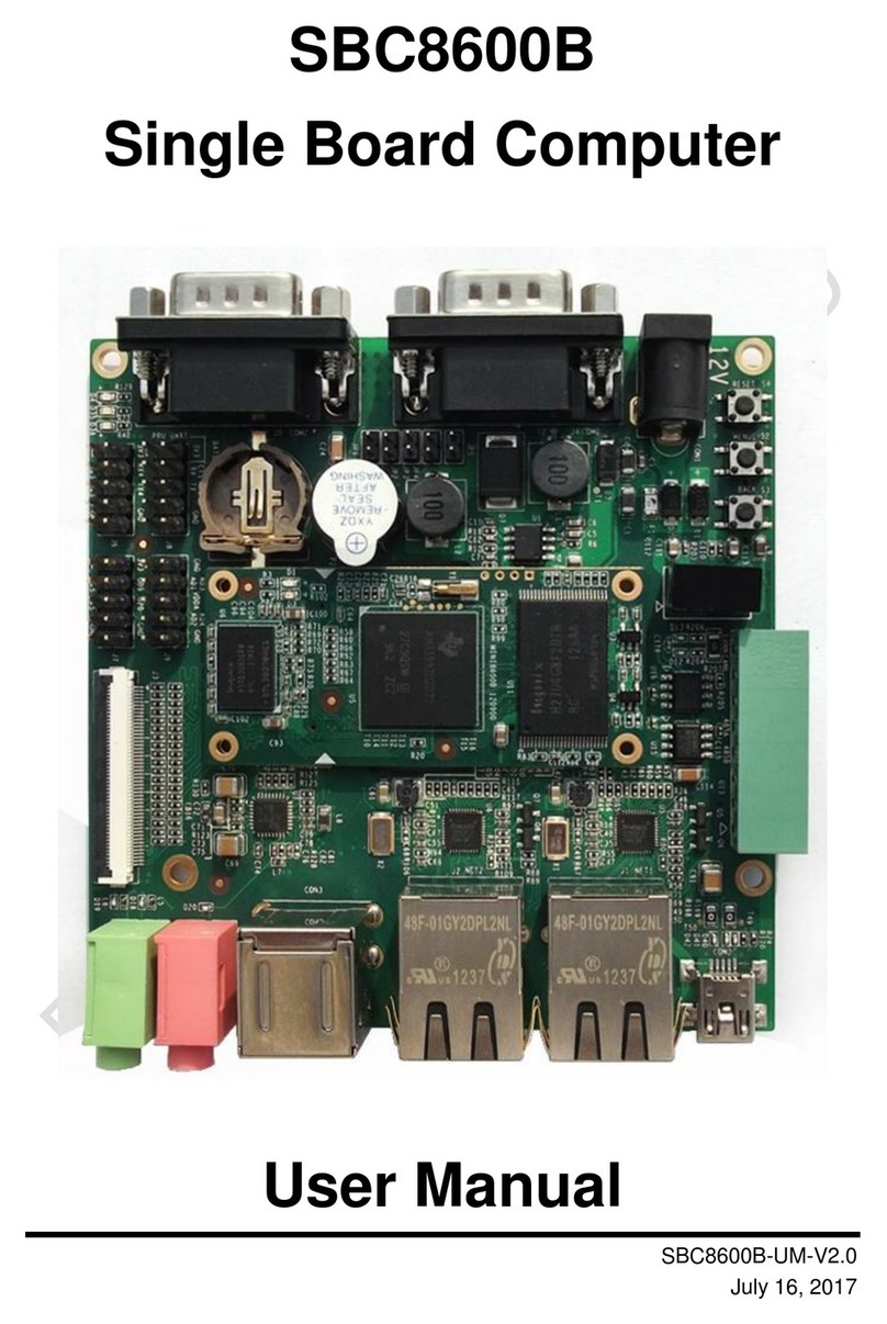
Embest SBC8600B User manual

Embest
Embest SBC6345 User manual

Embest
Embest Altera Lark Board User manual

Embest
Embest SBC8018 User manual

Embest
Embest EB-SAM3U User manual

Embest
Embest AM3517 User manual

Embest
Embest SBC6300x User manual

Embest
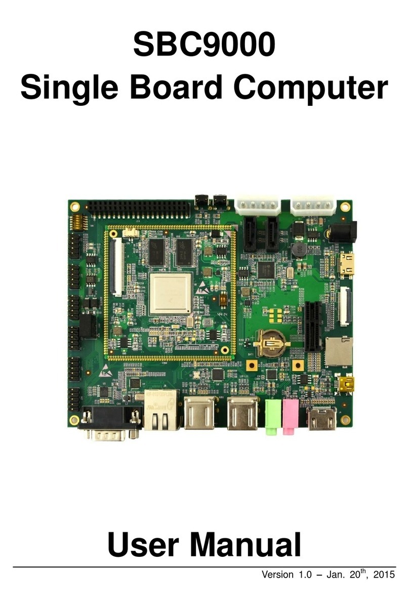
Embest SBC9000 User manual

Embest
Embest SBC6245 User manual

Embest
Embest SBC6300x User manual
Popular Motherboard manuals by other brands

Linear Technology
Linear Technology DC1705C Demo Manual

Avalue Technology
Avalue Technology ECM-QM77 user manual

Linear Technology
Linear Technology DC1783A-A Demo Manual

Critical Link
Critical Link MityCAM-3U5MGXS quick start guide

Kobian
Kobian Mercury KOB PLE133 FSMX manual

protech
protech Prox-1655 user manual