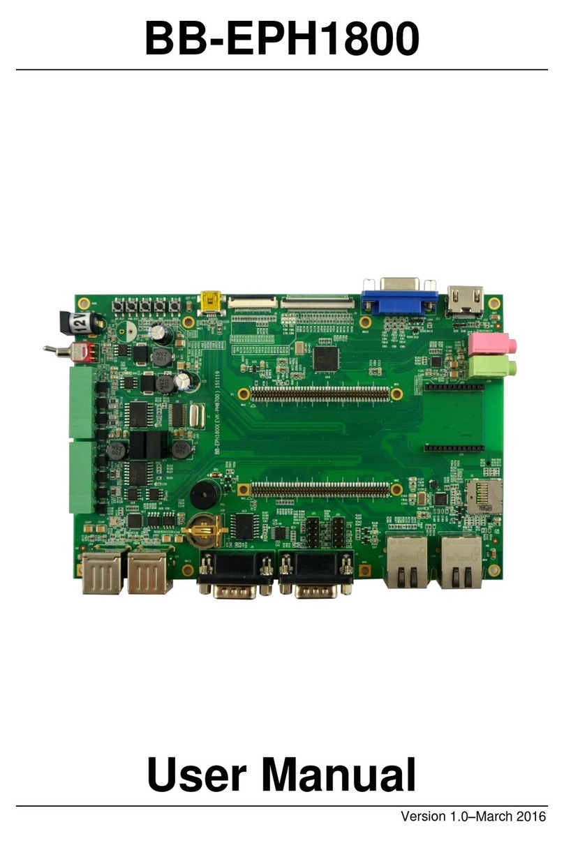
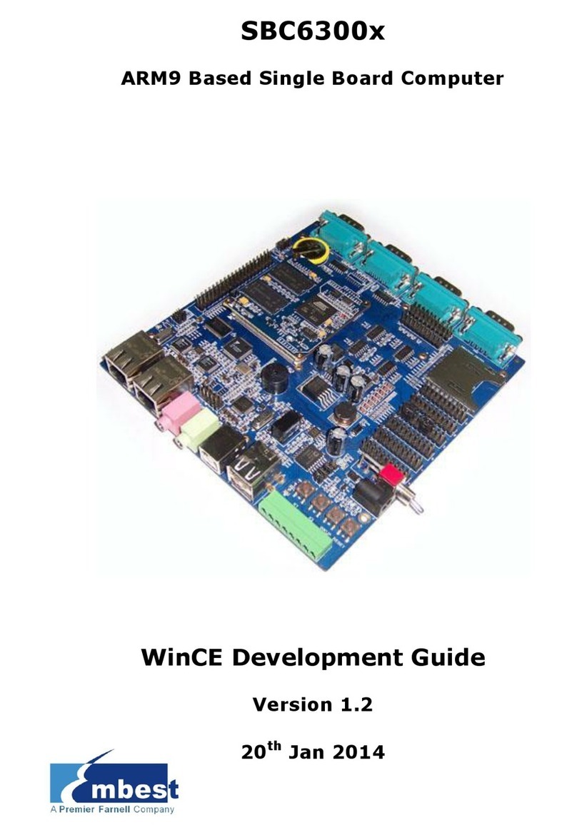
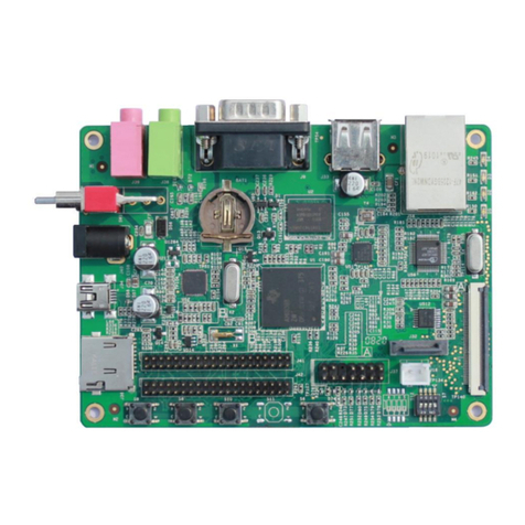
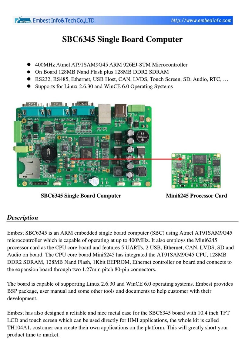
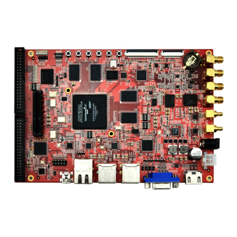
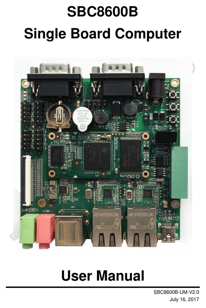
Embest SBC6300x User manual

SBC6300x
ARM9 Based Single Board Computer
Hardware Manual
Version 1.1
16th Jan 2014

Copyright Statement:
SBC6300x and its related intellectual property are owned by
Shenzhen Embest Technology Co., Ltd.
Shenzhen Embest Technology has the copyright of this document
and reserves all rights. Any part of the document should not be
modified, distributed or duplicated in any approach and form
without prior written permission issued by Embest Technology
Co., Ltd
Revision History:
Version
Date
Description
1.0
21/10/2013
Original Version
1.1
15/01/2014
Localisation

Table of Contents
1 Overview ........................................................................... 1
1.1 Product Information .........................................................1
1.2 Kit contents ....................................................................1
1.3 Board Interfaces..............................................................2
1.4 System Block Diagram .....................................................3
1.5 Physical Dimensions.........................................................4
2 Hardware Features ............................................................ 5
2.1 Processor .......................................................................5
2.2 On-Board Memory ...........................................................5
2.3 Core Board Functions .......................................................6
2.4 Main Board Functions .......................................................6
3 Hardware Details............................................................... 8
3.1 Interfaces .......................................................................8
3.1.1 Power(J26,J1)...................................................................... 8
3.1.2 NET0(J3)............................................................................... 8
3.1.3 NET1(J12)............................................................................. 9
3.1.4 UART(8 channels)................................................................. 10
3.1.5 DEBUG(DEBUG).................................................................... 10
3.1.6 COM0, 1 (COM0, COM1) ........................................................... 10
3.1.7 COM2(COM2)....................................................................... 11
3.1.8 EXT_COM(J23)..................................................................... 12
3.1.9 Matrix keyboard(J16)............................................................ 13
3.1.10 USB device(J9)................................................................... 14
3.1.11 USB HOST(J5).................................................................... 15
3.1.12 SD card(J15)...................................................................... 15
3.1.13 Audio (J17,J18) ..................................................................... 15
3.1.14 JTAG (J8).............................................................................. 16
3.1.15 TFT LCD (J20) ....................................................................... 17
3.1.16 Keys..................................................................................... 19
3.1.17 Touch screen(J20).............................................................. 19
3.1.18 Panel(J6)........................................................................... 19
3.1.19 GPIO(J4,J25,J6).............................................................. 20
3.1.20 CAN (J26) ............................................................................. 23
3.1.21 TWI (J25) ............................................................................. 23
3.1.22 BUZZER (BUZZ)..................................................................... 24
3.1.23 ADC (J19) ............................................................................. 24
4 Electrical System Description .......................................... 25
Appendix 1: 3.5” LCD ......................................................... 28
Appendix 2: 4.3, 5.6, 7” LCD:.............................................. 29
Appendix 3: ESD Precautions & Handling Procedures......... 30
Appendix 4: Technical support & Warranty ........................ 31
4.1 Technical support service................................................31
4.2 Maintenance service clause ............................................. 32
4.3 Basic guidelines for protection and maintenance of LCDs ....33
4.4 Value Added Services.....................................................34

Page | 1
1Overview
1.1 Product Information
The SBC6300X is a single board computer (SBC) designed and built by
Embest. The SBC is based on the Atmel AT91SAM9263 MCU with a 32-
bit ARM instruction set and a complete embedded software environment.
It has a flexible design with a tiny controller board (Mini6300); mounted
directly on an expansion board through two 0.8mm 100pin Free Height
(FH) surface-mount connectors. The CPU board of SBC6300X has the
ARM9 processor and memory on board. The expansion board offers
various hardware interfaces including 8 UARTs, 2 Ethernet ports, USB
Host and Device, CAN, TWI, LCD, Touch Screen, Keyboard, SD card,
Jtag, Audio and etc.
The rich industrial bus interface resources of this sing board computer
makes it ideal for embedded applications requiring wide operating
temperature ranges, and flexible I/O connectivity. It can be used in
many application fields, such as:
Medical Equipment,
Industrial Field Control,
Smart Instrumentation,
Industrial Control Devices,
Monitoring,
Automotive Electronics.
1.2 Kit contents
SBC6300X board
USB cable
Serial cable
Ethernet Cable
12V power adapter
Optional 4.3” or 7” LCD

Page | 2
1.3 Board Interfaces
Figure 1: SBC6300X Board Interfaces

Page | 3
1.4 System Block Diagram
Figure 2: SBC6300x System Block Diagram

Page | 4
1.5 Physical Dimensions
Figure 3: SBC6300x Physical Dimensions

Page | 5
2Hardware Features
The SBC6300x consists of:
Main board(150 x 143.5mm)
Core board(52 x 52mm)
And the following optional modules:
LCD module 3.5”(240 x 320mm)
LCD module 4.3”(480 x 272mm)
LCD module 5.6”(640 x 480mm)
LCD module 7.0”(800 x 480mm)
2.1 Processor
AT91SAM9263,ARM926EJ-STM ARM
Extended DSP instruction
ARM Jazelle technology providing Java acceleration capability
16K data butter, 16K instruction buffer, write buffer
Work performance goes up to 220 MIPS when the frequency is
200MHz
Memory management unit
Embedded ICE, support for Debug Communication Channel
Medium sized, embedded macrocell structure
2.2 On-Board Memory
128K on-chip ROM, single-cycle visit at maximum bus access
80K on-chip SRAM, single-cycle visit at maximum processor or
bus access

Page | 6
2.3 Core Board Functions
Categories
Function
Parameters
Processor
CPU
Atmel AT91SAM9263, ARM9,200MHz
Memory
SDRAM
64MB
NAND Flash
128MB
Data Flash
4MB
NOR Flash
4MB
EEPROM
2Kb
Others
LED
1 LED for System Status Indicator
Dimensions of core board: 52 x 52mm
Connector type: Tyco 5179031-4
2.4 Main Board Functions
Categories
Function
parameters
Memory
SD card
SDIO mode supports Hot-swapping
Power
Power input
8~20V, default 12V power input
Power Output
5V & Vin
Communication
UART
DEBUG: RS232/TTL 3line
COM0: RS232/TTL 5 line
COM1: RS232/TTL 5 line
COM2: RS232/TTL/half duplex RS485(isolated)
3line
COM3-6: RS232/TTL 5 line extended
CAN
CAN2.0 communication interface
NET0
MAC in MCU,10/100Mbps with LED
EXT_NET
DM9000 extend net,10/100Mbps with LED
USB Host
2-channel USB 2.0 HOST

Page | 7
USB Device
1-channel USB 2.0 device
TWI
MAX:400Kbps, slave or master mode
LCD
TFT LCD
2048 x 2048 (max), 16bit RGB mode, with 3.5,
4.3, 5.6 & 7”LCD support
In/output
Touch screen
4 line resistance touch screen connector
Matrix keyboard
6x6 Matrix keyboard , can be used for general IOs
Audio In
Audio input
Audio Out
Play MP3, provide 1.5W audio amplifier output
through pin headers
ADC
8 channel 12bit ADC input
General
GPIO
41 GPIO, multiplex
ISI connector
4channel PWM
1 channel SDIO connector
1 channel SPI1 connector(4 CS)
Buzzer
1 BUZZER controlled by a GPIO
JTAG
Standard 20PIN JTAG debug interface
Key
2 GPIO keyboard,1 WKUP key, 1 RESET key
Panel
Power input indicator, main board power indicator,
Provide WKUP, IO, RESET, power switch panel
connector
Other
Watchdog
RTC
RTC (with backup battery)

Page | 8
3Hardware Details
3.1 Interfaces
3.1.1 Power(J26,J1)
Power input: DC jack J1 and 2PIN3.81mm wire connector
Pin 2 in j26 can be used as power input and output ,1500mA
limited
Pin 3 in j26 can be used as power output only ,500mA limited
Vout=Vin=12V
GND
1
+12V
2
+5V
3
GND_485
4
485A
5
485B
6
CAN_L
7
CAN_H
8
3.1.2 NET0(J3)
Ethernet (WAN), 10/100M, with status indicator and isolation
transformer RJ45
MCU internal MAC
RJ45 Interface definition:
TX+
1
2
TX-
RX+
3
4
+2.5V
+2.5V
5
6
RX-
NC
7
8
NC
+3.3V
9
10
LED1
LED2
11
12
+3.3V

Page | 9
Resource from MCU:
MAC
PC25
ERXDV
PE21
ETXCK
PE23
ETX0
PE24
ETX1
PE25
ERX0
PE26
ERX1
PE27
ERXER
PE28
ETXEN
PE29
EMDC
PE30
EMDIO
PE31
INT_output
3.1.3 NET1(J12)
Extended by M9000CEP, resources from the MCU are as follows:
DM9000
D0-D15
A2
PD4
INT
PD11
EBI0_NCS2
RJ45 Interface definition:
TX+
1
2
TX-
RX+
3
4
+2.5V
+2.5V
5
6
RX-
NC
7
8
NC
+3.3V
9
10
LED1
LED2
11
12
+3.3V

Page | 10
3.1.4 UART(8 channels)
UART connectors(DEBUG,COM0,COM1,COM2,J23)
3.1.5 DEBUG(DEBUG)
Resources from the MCU are as follows:
DEBUG
PC30
DRXD
PC31
DTXD
Signal input/output level: RS232
Maximum data rate: 115.2kbps
Flow Control: None
Connector: DR9 male
At the same time lead out through pin headers with TTL
3.1.6 COM0, 1(COM0, COM1)
Resources from the MCU are as follows:
UART0
PA26
TXD0
PA27
RXD0
PA28
RTS0
PA29
CTS0
UART1
PD0
TXD1
PD1
RXD1
PD7
RTS1
PD8
CTS1
Signal input/output level: RS232
Maximum data rate: 115.2kbps
Flow Control: CTS, RTS
Connector: 2.54mm pitch connector/DR9(RS232)

Page | 11
3.1.7 COM2(COM2)
Resource from MCU as follows:
485/UART2
PD2
TXD2
PD3
RXD2
PD13
RE/DE(485)
Signal input/output level: RS232/RS485(with isolation)
Maximum data rate: 115.2kbps
Flow Control: none
Connector: 2.54mm pitch connector(TTL)/DR9(RS232)
Direction of RS485: PD130 send
1 receive
RS485 connector definition:
1
GND
2
+12V
3
+5V
4
GND_485
5
485A
6
485B
7
CAN_L
8
CAN_H
The DEBUG,COM0,COM1,COM2,TTL level on J27 definition as
follows:
default
RS232
COM0
GND
1
2
GND
DEBUG
TTL
TXD0R
3
4
PD2
RXD0R
5
6
PD3
RTS0R
7
8

Page | 12
CTS0R
9
10
GND
COM2
TTL
default
RS232
COM1
RXD1R
11
12
PC31
RXD1R
13
14
PC30
RTS1R
15
16
CTS1R
17
18
GND
19
20
The DR9 male connector definition as follows:
Pin number
Function
1、4、6、9
NC
2
RXD
3
TXD
5
GND
7
CTS
8
RTS
3.1.8 EXT_COM(J23)
These uarts come from the SC16C554,5lines,default RS232 and offer
support for TTL by changing resistors according your need.
Resources from the MCU are as follows:
EXT_COM
A0-A6
Sys bus
D0-D6
Sys bus
PD6
EBI0_NCS4
PE16
INT1
PA23
INT2
PA24
INT3
PA25
INT4

Page | 13
J23 connector definition as follows:
GND
1
2
GND
EXT_COM1_TXD
3
4
EXT_COM3_TXD
EXT_COM1_RXD
5
6
EXT_COM3_RXD
EXT_COM1_RTS
7
8
EXT_COM3_RTS
EXT_COM1_CTS
9
10
EXT_COM3_CTS
EXT_COM2_TXD
11
12
EXT_COM4_TXD
EXT_COM2_RXD
13
14
EXT_COM4_RXD
EXT_COM2_RTS
15
16
EXT_COM4_RTS
EXT_COM2_CTS
17
18
EXT_COM4_CTS
GND
19
20
GND
3.1.9 Matrix keyboard(J16)
Dual pin headers 2.54mm
These pins can be used as general IOs or 6x6 matrix keyboard
Voltage : 0V (low), 3.3V (high)
Resources from the MCU are as follows:
GPIO/KEYBOARD
PB6
IO(pull up)
PB7
IO(pull up)
PB11
IO(pull up)
PB19
IO(pull up)
PB20
IO(pull up)
PB21
IO(pull up)
PB22
IO
PB23
IO
PB24
IO

Page | 14
PB25
IO
PB26
IO
PB27
IO
J16 connector definitions are as follows:
VDD33
1
2
VDD33
PB22
3
4
PB6
PB23
5
6
PB7
PB24
7
8
PB11
PB25
9
10
PB19
PB26
11
12
PB20
PB27
13
14
PB21
GND
15
16
GND
GND
17
18
GND
19
20
3.1.10 USB device(J9)
Standard type-B connector
Resources from MCU (DDP, DDM, PD9, PD14)
PD14 is used for USB detection
Max:12Mbps
Pin
Signal
Function
1
VBUS
Power supply (+5V)
2
D-
USB signal
3
D+
USB signal
4
GND
Power supply (GND)

Page | 15
3.1.11 USB HOST(J5)
Dual type-A connector
500mA current limited
Max: 12Mbps
Resources from MCU (HDMA, HDPA, HDMB, HDPB)
+5V
1
5
+5V
USBM0
2
6
USBM1
USBP0
3
7
USBP1
GND
4
8
GND
3.1.12 SD card(J15)
SDIO mode
Standard SD card connector
Resources from MCU:
SDCARD
PA6
MCI1_CK
PA7
MCI1_CDA
PA8
MCI1_DA0
PA9
MCI1_DA1
PA10
MCI1_DA2
PA11
MCI1_DA3
PA30
Insert detect
PD12
Write protect
3.1.13 Audio (J17,J18)
Standard 3.5mm headphone connectors
J17: headphone
J18: MIC
Resources from MCU

Page | 16
AC97
PB0
AC97FS
PB1
AC97CK
PB2
AC97TX
PB3
AC97RX
PE22
NC(RESET_AUDIO)
Besides the audio signal lead out on U9(2*5pin headers 2.54mm), U9
definitions as follows:
VOUT_R
1
2
VOUT_L
LINE_R
3
4
LINE_L
GND
5
6
GND
MIC_2
7
8
MIC_1
SPK_A
9
10
SPK_B
SPK_A SPK_B can be connected to a speaker(<=1.5W)
3.1.14 JTAG (J8)
VDD33
1
2
VDD33
NTRST
3
4
GND
TDI
5
6
GND
TMS
7
8
GND
TCK
9
10
GND
RTCK
11
12
GND
TDO
13
14
GND
Nreset
15
16
GND
17
18
GND
19
20
GND
Other manuals for SBC6300x
1
Table of contents
Other Embest Motherboard manuals

Embest
Embest Altera Lark Board User manual

Embest
Embest AM3517 User manual

Embest
Embest EB-SAM3U User manual

Embest
Embest SBC6300x User manual

Embest
Embest SBC6245 User manual

Embest
Embest SBC8018 User manual

Embest
Embest SBC6345 User manual

Embest
Embest BB-EPH1800 User manual

Embest
Embest SBC9000 User manual

Embest
Embest SBC8600B User manual
Popular Motherboard manuals by other brands

Aaeon
Aaeon EPIC-QM77 manual

Texas Instruments
Texas Instruments PGA308EVM user guide

Advantech
Advantech PCL-730 user manual

Lattice Semiconductor
Lattice Semiconductor RT CrossLink-NX quick start

Spectrum Digital
Spectrum Digital eZdsp F28335 Quick start installation guide

Texas Instruments
Texas Instruments LM63625EVM user guide