EMBRON HATTELAND TECHNOLOGY X MMD G2 Series User manual

Please visit www.hattelandtechnology.com for the latest electronic version of this manual.
Applies for Series X G2 Maritime Multi Display (MMD):
HD 15T22 MMD-xxx-xxxx
HD 17T22 MMD-xxx-xxxx
HD 19T22 MMD-xxx-xxxx
HD 24T22 MMD-xxx-xxxx
HD 26T22 MMD-xxx-xxxx
HD 27T22 MMD-xxx-xxxx
Serial/Ethernet/USB Communication Control Interface (SCOM)
TECHNICAL
MANUAL
Technical Manual SCOM Series X MMD G2
Updated: 08 Nov 2021 Doc Id: INB100018-6 (Rev 14)
Created: 363 Approved: 6644

Copyright © 2021 Hatteland Technology AS
Eikeskogvegen 52, N-5570 Aksdal, Norway.
All rights are reserved by Hatteland Technology AS. This information may not, in whole or in part, be
copied, photocopied, reproduced, translated or reduced to any electronic medium or machine-
readable form without the prior written consent of Hatteland Technology AS. Review also:
www.hattelandtechnology.com/hubfs/pdf/misc/doc100703-1_permission_to_create_user_manuals.pdf
The products described, or referenced, herein are copyrighted to the respective owners.
The products may not be copied or duplicated in any way. This documentation contains proprietary
information that is not to be disclosed to persons outside the user’s company without prior written consent
of Hatteland Technology AS.
The copyright notice appearing above is included to provide statutory protection in the event of
unauthorized or unintentional public disclosure.
All other product names or trademarks are properties of their respective owners !
WARNING: This is a class A product. In a domestic environment this product may cause radio interference
in which case the user may be required to take adequate measures.
Statement above last revised 31 Jul. 2019

3
IND100130-51
3
Contents
Contents................................................................................................. 3
Serial/Ethernet/USB Communication (SCOM) Interface......................5
Introduction...........................................................................................5
Serial / USB Interface Conguration .................................................................................................... 5
Ethernet Interface Conguration .......................................................................................................... 7
Cables.................................................................................................................................................. 7
Electrical Interface................................................................................................................................ 7
SCOM Introduction............................................................................................................................. 10
Data Rates ......................................................................................................................................... 10
Data Format Serial Mode................................................................................................................... 10
Message Format ................................................................................................................................ 10
Attention (ATTN) ............................................................................................................................... 10
Address (ADDR) ................................................................................................................................ 11
Message Commands and Queries (CMD) Contents ......................................................................... 12
Data Length (LEN) ............................................................................................................................. 13
Inverse Header Checksum (IHCHK).................................................................................................. 13
Data Field (DATA) .............................................................................................................................. 13
Inverse Data Checksum (IDCHK) ...................................................................................................... 13
SCOM Section: Brightness.................................................................14
"BRI" - Minimum Backlight Brightness ............................................................................................... 15
"BRM" - Maximum Backlight Brightness ........................................................................................... 16
"BRT" - Brightness Control................................................................................................................. 17
"BRL" - GDC LED Brightness Control................................................................................................ 18
"BRU" - User Brightness Control........................................................................................................ 19
SCOM Section: Glass Display Control™(GDC).................................20
"GMB" - Buttons Minimum Brightness ............................................................................................... 20
"GBF" - Keypad Brightness auto follow.............................................................................................. 21
"LIS" - Read Ambient Light Sensor .................................................................................................... 24
"ODM" - Outdoor Mode...................................................................................................................... 25
"REC" - Recall GDC........................................................................................................................... 26
"POT" - Backlight Control Interface selection..................................................................................... 27
SCOM Section: Buzzer ......................................................................28
"BZZ" - Buzzer Control....................................................................................................................... 28

4
IND100130-51
4
Contents
SCOM Section: Service......................................................................30
"SWI" - Main Software Version Query................................................................................................ 30
"SWV" - Video Scaler Software Version Query.................................................................................. 30
"TYP" - Type/Model Number Query ................................................................................................... 31
"SNB" - Serial Number Query ............................................................................................................ 31
"SCI" - Store Customer Service ID..................................................................................................... 32
"CSI" - Read Customer Service ID..................................................................................................... 32
"ETC" - Elapsed Time Counter .......................................................................................................... 32
"MAN" - Read Manufacturer data....................................................................................................... 33
"TMP" - Read Temperature Sensor ................................................................................................... 33
"VER" - Read Specic Type ............................................................................................................... 34
"FWV" - Read Firmware information .................................................................................................. 34
SCOM Section: Interface....................................................................35
"CBR" - COM Ports Baudrate Conguration...................................................................................... 35
"BAK" - Broadcast Acknowledgement................................................................................................ 36
SCOM Section: ECDIS.......................................................................37
"DLN" - Download package................................................................................................................ 37
"DL?" - Request Number of packages available................................................................................ 38
"CAL" - Calibration brightness level ................................................................................................... 39
SCOM Section: Factory......................................................................40
"RCF" - Recall Factory Conguration................................................................................................. 40
SCOM Section: Power .......................................................................41
"PWR" - Power On/O/Sleep unit ...................................................................................................... 41
SCOM Section: Video Scaler .............................................................42
"VUR" - Read User Conguration from Video Scaler......................................................................... 42
"VUS" - Store User Conguration to Video Scaler............................................................................. 43
SCOM Section: OSD Control Functionality........................................44
"MOD" - Operation Mode Selection ................................................................................................... 44
"MCC" - OSD Control Functionality.................................................................................................... 45
MCC Commands List......................................................................................................................... 46
Comments to MCC Command table .................................................................................................. 53
Operational Requirements ................................................................................................................. 54
Unit Response and Addresses........................................................................................................... 55
Additional Commands........................................................................................................................ 55
Appendixes .......................................................................................... 57
Calculating Checksums (IDCHK, IHCHK)..........................................58
HEX, ASCII, BIN and Character table ................................................61
C# / Pseudo Ethernet/TCP Code example.........................................66
Revision History .................................................................................67

5
IND100084-17
Introduction
This document denes the electrical interface, serial data format, and communication protocols of the Serial
Communication Control Interface (SCOM). The purpose of this interface is to enable a computer application to control
one or more units. Unit refer to display product. Interface conguration done within OSD Menu.
Serial / USB Interface Conguration
The serial / USB interface can have dierent congurations dened as follows:
RS-232 One computer controls one unit, no individual address
USB One computer controls one unit, no individual address
4-wire RS-485/RS-422 One computer controls units, each with individual address.
2-wire RS-485 One computer controls units, each with individual address.
Each unit will be assigned with an address value before it is connected to a shared network. The user application
(PC) can send the message to the specic unit by marking the message with corresponding address number. The
unit which has the matching address will respond immediately, while the others keep silent.
Broadcast commands will be processed by all linked units simultaneously once the last byte of the message is
received. In order to avoid coniction on bus, each unit should respond back at dierent times. As the units are
working independently, they can hardly know how many units are linked in the same bus. In this case, the interval
between receiving message and responding back should be calculated in the base of their own address. The lowest
addressed unit will respond rst.
To calculate the address based interval, there is a formula to calculate the interval (Te):
Te = (Tr +Lr) * N, where
Lr = length of the ACK/NAK message response
Tr = Response time
N = the total number of monitors
Response time Tr is a xed value which are calculated to make sure there is no conict on the bus. Principally, Tr is
equivalent to 2.5 byte periods after the last byte of a command message is received. However, due to the dierence
in microcontroller clock, all the units may not nish the message receive at the same timing point. So the Tr should be
calculated based on the jitter changes.
Illustration: Broadcast Message: Timing 1
Serial/Ethernet/USB Communication (SCOM) Interface

6
Serial/Ethernet/USB Communication (SCOM) Interface
IND100084-17
Illustration: Broadcast Message: Timing 2
Illustration: Broadcast Message: Timing 3
User computer is linked with three units via the RS485 bus. These three units are assigned in address: 0, 1, 3. At the
beginning, User computer broadcast a message to all connected units. Assuming all of them nish receiving at the
same time, then the address ‘0’ unit will respond with no latency. The other two units with higher address, stay silent
until the calculated delay expires.
For the user computer, there is also a formula to calculate the interval between broadcast message. After the
previous message was sent, the next message should not be issued until:
Tc =Te_max + Tg, where
Te_max = Max(Te)
Tg = the receiving time of 5 bytes.
For example, a test computer connects 8 units on bus, the interval between broadcast messages is calculated as:
Tc = (Tr + Lr) * 8 + Tg.

7
Serial/Ethernet/USB Communication (SCOM) Interface
IND100084-17
Illustration: Addressed Message
In the scenario that user computer sends out the message to specic address, the unit which owns the matching
address will respond immediately, while the other keep silent.
Ethernet Interface Conguration
The Ethernet/LAN/Network interface are selected by the OSD menu. The conguration is dened as follows:
Ethernet One computer controls units via Automatic IP or Fixed IP through port 10001. IP address
for the computer must be on the same subnet as the internal set IP of the unit. The local
software rewall on computer, router or network system must accept
communication in/out on port 10001 (open port).
The SCOM message contained in TCP is the same as the one used in RS232/485/422.
Check the section later in this manual “C# / Pseudo Ethernet/TCP Code example”.
Cables
Serial Mode: A cable with an overall shield terminated at the back shell should be used.
Ethernet Mode: A CAT-5, CAT-6 cable capable of 10/100/1000Mbps bandwidth transmissions.
USB Mode: A USB Type A-A (male-male) cable, less than 5meters is recommended.
Electrical Interface
Electrical signals shall conform to RS-485, RS-422, RS-232, USB or Ethernet standards. Only Receive Data,
Transmit Data, and Signal Ground are used. The same conditions apply for both Serial mode 4-wire (Full Duplex) and
2-wire (Half Duplex), and will just be referred to as RS-485 in this document. Hardware handshake is only supported
by loopback handshake for RS-232.

8
Serial/Ethernet/USB Communication (SCOM) Interface
IND100084-17
- Compatible connectors (as listed on datasheets):
• SCOM RS-422/485 : Terminal Block Connector 3.81, non-isolated
• SCOM RS-232 : D-SUB 9P (female), non-isolated
• SCOM Ethernet : RJ45 (female)
• SCOM USB : USB 2.0 (Type A, female)
Multiple access:
From Firmware NXP: FW1000002-0A25 and Firmware Video Scaler: FW200001-0BV8 Series X G2 MMD models
supports multiple SCOM access via RS-232, Ethernet, USB and RS-422 or RS-485 ports at the same time.
This means, for example, that while using Ethernet through a RJ-45 port to communicate with unit, users can now also
at the same time communicate via RS-232 port simultaneously. Only limitation is for RS-422 and RS-485 at the same
time which is not possible.
Reference:
https://www.hattelandtechnology.com/product-notications/rmware-update-aecting-series-x-g2-mmd-displays-15-to-27-inch-1
For models having older rmware as described above, the selection of active communication must be set via the
OSD menu setting item: “Management Settings - Communication”. This will only allow 1 connection at the same time
through the dened connector.

9
Serial/Ethernet/USB Communication (SCOM) Interface
IND100084-17
10-pin RS-422 / RS-485 Module
“RS-422/RS-485 SCOM + Buzzer”
(Internal Buzzer can be controlled externally)
2 4 6 8 10
1 3 5 7 9
PIN 01* RxD+ Receive Data Positive
PIN 02 GND Ground
PIN 03* RxD- Receive Data Negative
PIN 04 +5V +5V Out
PIN 05* TxD+ Transmit Data Positive
PIN 06** BUZ- Buzzer Control Negative
PIN 07* TxD- Transmit Data Negative
PIN 08** BUZ+ Buzzer Control Positive
PIN 09 GNDR Ground 100Ω
PIN 10 GND Ground
*Pin 1,3,5,7 = RS-485 Full Duplex (4-wire)
*Pin 5,7 = RS-485 Half Duplex (2-wire)
**See notes in blue.
Suggested “Buzzer” Control Logic inside
Computer/System:
Pin “6”
Logic Control
GND
+12V
NPN
Transistor
Rating:
500mA
Internal Side External Side
Pin “8”
Connect T.Block
to upper row
Note:
To ensure that EMC requirements are met, we
recommend that the cable is screened and screen
is terminated/grounded at both ends with as short
as possible pig tail.
For Military/Naval use: +12V line from customer
system should be low pass lter or else the power
ripple may cause radiated emission to fail.
Use a cable that contains at least 2 wires (not 2
single wires). Test connection (beep) with Voltage
Meter. Wires may be combined if using RS-422/485
COM as well.
Serial COM RS-232 non-isolated, 9-pin DSUB Female
5 4 3 2 1
9 8 7 6
PIN 01** BUZ+ Buzzer Control Positive IN*
PIN 02 TxD Transmit Data
PIN 03 RxD Receive Data
PIN 04 DTR Data Terminal Ready
PIN 05 GND Ground
PIN 06 DSR Data Set Ready
PIN 07 RTS Request To Send
PIN 08 CTS Clear To Send
PIN 09** BUZ- Buzzer Control Negative IN*
RS232-Wake On Ring is not enabled. **See notes in blue.
Suggested “Buzzer” Control Logic inside Computer/System:
Pin 1 on your Connector
Pin 1 Pin 9
9-pin DSUB Male Add
Note Orientation! Back Shell
Logic Control
GND
+12V
NPN
Transistor
Rating:
500mA
Internal Side External Side
Note: Requires soldering and assembly. It is expected that the
technician has experience in electronics, soldering and assembling cables and
connectors. Use a cable that contains at least 2 wires (not 2 single wires). Heat
Shrink Tubes must be applied to soldered wire/pins. Test connection (beep)
with Voltage Meter. Wires may be combined if using RS-232 COM as well.
8-pin RJ45 10/100/1000Mbps LAN/Ethernet
1 2 3 4 5 6 7 8
PIN 01 D0P+ Di erential Pair 0 (Positive)
PIN 02 D0N- Di erential Pair 0 (Negative)
PIN 03 D1P+ Di erential Pair 1 (Positive)
PIN 04 D2P+ Di erential Pair 2 (Positive)
PIN 05 D2N- Di erential Pair 2 (Negative)
PIN 06 D1N- Di erential Pair 1 (Negative)
PIN 07 D3P+ Di erential Pair 3 (Positive)
PIN 08 D3N- Di erential Pair 3 (Negative)
4-pin USB2.0 TYPE A
Pin 2: Negative Data
Pin 1: VCC +5V Pin 3: Positive Data
Pin 4: Ground
**Buzzer - External Drive Logic:
• Able to supply 12VDC+-5%@100mA
• Short circuit protected at <500mA
• <50VDC from ground of Display unit
(Our input is isolated, this is layout limitation)
• Our input is classi ed as signal input, not power.
Notes:
Unit may have several physical connectors available
for Buzzer control. Please only use RS-232 or RS-485
pins to control Buzzer, not both at the same time.
Series X (G1 - Generation 1):
• External drive logic can drive the buzzer even when
the Display Unit is o .
Series X (G2 - Generation 2) / MVD Series:
• Display Unit needs external power connected
to turn buzzer on. (Any logic power state).
For Pin Out assignments, please review the following diagrams that covers all units and connector types:
Connectors illustrated here are either standard by factory default or may be available (through factory customization).
Note that some combinations may not be possible due to space restrictions. List also valid for customized models. All
pin out assignments are seen from users Point of View (POV) while looking straight at the connector. Please review
the dedicated datasheet or technical drawings for your actual unit to identify and determine the presence of desired
connector.
10
Serial/Ethernet/USB Communication (SCOM) Interface
IND100084-18
SCOM Introduction
The SCOM commands specied in this document are of the same structure as older versions of Hatteland
Technology SCOM commands for other products. This format will be explained in the following sections.
Data Rates
The unit is congured to transmit and receive data at 9600 bits/second (Serial mode) or via standard Ethernet
10/100/1000Mbps connection through port 10001.
Data Format Serial Mode
Data shall be transmitted with no parity, 8 data bits, one start bit and one stop bit. XON/XOFF ow control should be
switched o/disabled.
Message Format
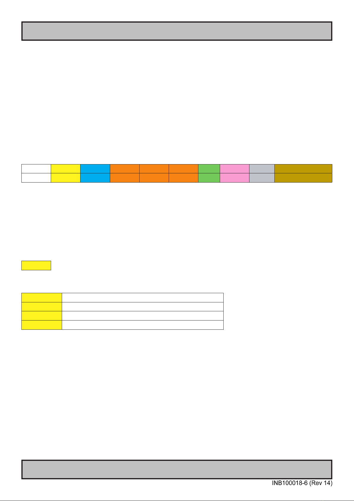
The basic message format shall be as follows:
Byte # 0 1 2 3 4 5 6 7 8 or 7+DATA=END
ATTN ADDR CMD CMD CMD LEN IHCHK DATA IDCHK
The minimum message size is 7 bytes (0x07). The maximum message size is 82 bytes (0x52), consistent with the
EN61162-1 standard. Colors will be used throughout this manual to indicate byte positions. Every byte sent are
viewed in this document as HEX values and are based on standard characters in the ASCII table (0 to 255) to send
or receive messages in a human readable input/output. No further decoding or decrypting functionality is needed or
required. Every command sent and received are always ended with a 0x00 (null byte terminator).
Byte 0 is sent rst then the rest of the bytes follow, there is no handshake during this transmissions. Bytes are sent as
fast as possible.
ATTN
Attention (ATTN)
This single byte is used to identify a start of message. 3 values are possible:
ATTN Description
0x07 Command, also known as ASCII BELL
0x06 Acknowledge, also known as ASCII ACK
0x15 Negative Acknowledge, also known as ASCII NAK
A device sends a command using the 0x07 Attention Code. The unit will respond to the command with either an ACK
if the command completed successfully, or a NAK if the command failed. The unit also replies with a NAK if the
command was not understood, invalid or unsupported. If a command description doesn't state dierently then with
NAK attention code the unit will return received data. The unit will ignore any message that doesn't start with
Command attention code.
NOTE: A complete HEX, ASCII, BIN and Character table overview are available in the APPENDIX chapter.

11
Serial/Ethernet/USB Communication (SCOM) Interface
IND100084-18
ADDR
Address (ADDR)
This single byte is used to specify a particular unit to receive a Command and to identify the unit responding (ACK
or NAK) to a Command. All units will support the broadcast address. The factory default adress is 0x00, while in this
manual illustrated throughout as 0xFF. Only in use when in RS-485/RS-422 mode. Otherwise 0xFF shall be used.
The Address eld shall have the following values:
ADDR Description
0xFF Broadcast - Addressed to all units
0x00 to 0xFE Address of a specic unit, 0 to 254 (max 255 units)

12
Serial/Ethernet/USB Communication (SCOM) Interface
IND100084-18
CMD
Message Commands and Queries (CMD) Contents
The command can be one of the following values and consists always of 3 bytes in positions 2,3,4:
Byte 2 Byte 3 Byte 4 ASCII Description I/O Non-Volatile / Volatile Page
0x42 0x52 0x49 BRI Minimum Brightness R/W NV 15
0x42 0x52 0x4D BRM Maximum Brightness R/W NV 16
0x42 0x52 0x54 BRT Brightness Control R/W V 17
0x42 0x52 0x4C BRL GDC LED Brightness Control R/W NV 18
0x42 0x52 0x55 BRU User Brightness Control R/W NV 19
0x47 0x4D 0x42 GMB GDC minimum brightness R/W NV 20
0x47 0x42 0x46 GBF Keypad Brightness auto follow R/W NV 21
0x4C 0x49 0x53 LIS Read Ambient Light Sensor R 24
0x4F 0x44 0x4D ODM Outdoor Mode R/W NV 25
0x52 0x45 0x43 REC Recall GDC W 26
0x50 0x4F 0x54 POT Potential Meter Control R/W NV 27
0x42 0x5A 0x5A BZZ Buzzer Control On/OFF R/W V 28
0x53 0x57 0x49 SWI Read NXP Firmware Version R 30
0x53 0x57 0x56 SWV Read Video Scaler Firmware Version R 30
0x54 0x59 0x50 TYP Read Type Number R 31
0x53 0x4E 0x42 SNB Read Serial Number R 31
0x53 0x43 0x49 SCI Write Customer Service ID W NV 32
0x43 0x53 0x49 CSI Read Customer Service ID R 32
0x45 0x54 0x43 ETC Elapsed Time Counter Query System R 32
0x4D 0x41 0x4E MAN Read Manufacture ID Code R 33
0x54 0x4D 0x50 TMP Read Temperature Sensor R 33
0x56 0x45 0x52 VER Inquiry specific Type Number R 34
0x46 0x57 0x56 FWV Inquiry Firmware Versions R 34
0x43 0x42 0x52 CBR COM1&2 Port Baudrate R/W NV 35
0x42 0x41 0x4B BAK Turn on/off acknowledge on broadcast command R/W NV 36
0x44 0x4C 0x4E DLN Download ECDIS Package R 37
0x44 0x4C 0x3F DL? Request Number of available ECDIS Pack R 38
0x43 0x41 0x4C CAL ECDIS calibrated brightness inquiry R 39
0x52 0x43 0x46 RCF Recall Factory default W 40
0x50 0x57 0x52 PWR Power On/Off/Sleep unit W 41
0x56 0x55 0x52 VUR Read User Configuration from Video Scaler R 42
0x56 0x55 0x53 VUS Write User Configuration to Video Scaler W 43
0x07 0xFF 0x4D MOD Operation Mode Selection R/W 44
0x4D 0x43 0x43 MCC OSD Menu Control Commands + Commands List Table* R/W 45-54
I/O = R=Read, W=Write.
Volatile = V=The variable values controlled by these commands are cleared at power restart).
Non-Volatile = NV=The variable values controlled by these commands are stored even after power restart.
Page # = Page number in this manual where command is detailed.
*MCC
OSD Menu Control Commands. "MCC" command also features a Query "?" mode, "R" or "r" reset mode to factory default,
increase +1 from current value "+" and decrease -1 from current value "-". Details and usage of these commands are available
later in this manual.

13
Serial/Ethernet/USB Communication (SCOM) Interface
IND100084-18
LEN
Data Length (LEN)
This single byte denes the length of DATA in the message in bytes. The maximum value for this eld is 74 bytes
(0x4A in HEX). The minimum value is 0 bytes (0x00 in HEX).
IHCHK
Inverse Header Checksum (IHCHK)
This single byte is a simple 8-bit checksum of the header data, message bytes 0 to 5 on which a bit-wise inversion
has been performed. The checksum will be initialised to 0. The 8-bit sum (without carry) of bytes 0, 1, 2, 3, 4, 5 and 6
will be 0xFF (255 in value). If the unit receives a message with an incorrect checksum, the unit will reply with the
attention code set to NAK and no data eld.
DATA
Data Field (DATA)
The bytes is the DATA eld which will only be transmitted if LEN is greater than 0. This eld depends on the CMD
transmitted.
IDCHK
Inverse Data Checksum (IDCHK)
This single byte will only be transmitted if LEN is greater than 0. This is a simple 8-bit checksum of the data eld,
message bytes 7 to 7+(LEN-1) on which a bit-wise inversion has been performed. The checksum will be initialised to
0. The 8-bit sum (without carry) of bytes 7 through 7+LEN inclusive will be 0xFF. The receiver will reply to any
message that the checksum has failed with the attention code set to NAK. Basically this byte is located at the very
end of a received stream.
NOTE: A complete HEX, ASCII, BIN and Character table overview are available in the APPENDIX chapter.
14
Serial/Ethernet/USB Communication (SCOM) Interface
IND100084-18
SCOM Section: Brightness
In SCOM protocol, there are ve brightness related commands, which dene the backlight/LED brightness value and
their adjustable range.
LCD Brightness : Full range of LCD backlight.
System Brightness : Full range of system level brightness.
User Brightness : Variation range of User level.
- BRI: Minimum backlight brightness.
- BRM: Maximum backlight brightness.
- BRT: Backlight brightness.
- BRU: User backlight brightness.
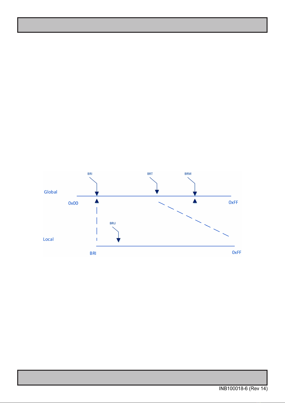
BRI and BRM value dene the min & max boundary of the visual backlight brightness. BRT gives the global backlight
brightness value. However, BRT should be the value between BRI and BRM.
BRU is the user backlight control which presents the user controlled brightness value. This value is linked with
potentiometer (when POT is valid). The adjustable scale for BRU value is 0 ~ 255. The corresponding PWM steps
behind BRU, is framed by BRI and BRT. The visual variation range for BRU is from BRI to BRT. The BRU steps are
scaled down into 255 by the value between BRI and BRT.
Illustration: Brightness Logic

15
Serial/Ethernet/USB Communication (SCOM) Interface
IND100084-18
"BRI" - Minimum Backlight Brightness
The command is used to set the minimum brightness of backlight. It denes the lower bound of the visual brightness
range. For example, if we set BRI to 10%, the minimum achievable brightness is 10% in PWM step curve.
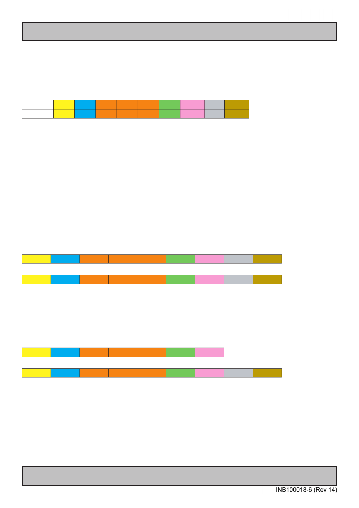
Byte # 0 1 2 3 4 5 6 7 8
0x07 0xFF 0x42 0x52 0x49 0x01 IHCHK Min Brightness IDCHK
Minimum Brightness: A value describing the minimum backlight brightness.
Range: [0x00-0xFF]
0x00: is o.
0xFF: is max brightness.
After unit reset the value is set to: last stored value.
After microcontroller reset the value is set to: last stored value. (0xFF if no stored value).
Write:
Sets the minimum backlight brightness. The brightness value shall be sent as 1 byte in the DATA eld.
Example:
Set 60% BRI:
0x07 0xFF 0x42 0x52 0x49 0x01 0x1B 0x99 0x66
ACK reply from unit:
0x06 0xFF 0x42 0x52 0x49 0x01 0x1C 0x99 0x66
Read:
Read the minimum backlight brightness. The length of data shall be zero.
Example:
Get BRI:
0x07 0xFF 0x42 0x52 0x49 0x00 0x1C
ACK reply from unit:
0x06 0xFF 0x42 0x52 0x49 0x01 0x1C 0x99 0x66

16
Serial/Ethernet/USB Communication (SCOM) Interface
IND100084-18
"BRM" - Maximum Backlight Brightness
The command is used to set the maximum brightness of backlight. It denes the upper bound of the visual brightness
range. For example, if we set BRM to 90%, the maximum achievable brightness is 90% in PWM step curve.
Byte # 0 1 2 3 4 5 6 7 8
0x07 0xFF 0x42 0x52 0x4D 0x01 IHCHK Max Brightness IDCHK
Maximum Brightness: A value describing the maximum backlight brightness.
Range: [0x00-0xFF]
0x00: is o.
0xFF: is max brightness.
After unit reset the value is set to: last stored value.
After microcontroller reset the value is set to: last stored value. (0xFF if no stored value).
Write:
Sets the maximum backlight brightness. The brightness value shall be sent as 1 byte in the DATA eld.
Example:
Set 60% BRM:
0x07 0xFF 0x42 0x52 0x4D 0x01 0x17 0x99 0x66
ACK reply from unit:
0x06 0xFF 0x42 0x52 0x4D 0x01 0x18 0x99 0x66
Read:
Read the minimum backlight brightness. The length of data shall be zero.
Example:
Get BRM:
0x07 0xFF 0x42 0x52 0x4D 0x00 0x18
ACK reply from unit:
0x06 0xFF 0x42 0x52 0x4D 0x01 0x18 0x99 0x66
17
Serial/Ethernet/USB Communication (SCOM) Interface
IND100084-18
"BRT" - Brightness Control
This command controls the display backlight brightness setting. If BRT is 100%, the user can adjust the user
brightness (BRU) from 0-100%. If the BRT is set to 60%, the visual brightness is set to 60%. The user can adjust
the user brightness (BRU) from 0-100% within the 60% set by BRT. If the user sets the user Brightness to half
(BRU=50%), the visual brightness will be 30% (half of 60%). If BRT is set back to 100%, the visual brightness will be
50% (half of 100%).
Byte # 0 1 2 3 4 5 6 7 8
0x07 0xFF 0x42 0x52 0x54 0x01 IHCHK BRT IDCHK
BRT: A value describing the brightness.
This command can only be set using SCOM and can not be adjusted directly by press of a button etc.
Range: [0x00-0xFF]
0x00: is o.
0xFF: is max brightness.
After unit reset the value is set to: Load BRT value from factory conguration le.
After microcontroller reset the value is set to: Load BRT value from factory conguration le.
Write:
The brightness value shall be sent as one byte in the DATA eld. Intermediate values will control brightness over the
range from minimum to maximum luminance.
Example:
Set 60% BRT:
0x07 0xFF 0x42 0x52 0x54 0x01 0x10 0x99 0x66
ACK reply from unit:
0x06 0xFF 0x42 0x52 0x54 0x01 0x11 0x99 0x66
Read:
Get the BRT variable. To trigger a BRT read command, the length of the DATA eld must be zero. The DATA eld in
the microcontroller reply will indicate the current brightness control setting.
Example:
GET BRT value:
0x07 0xFF 0x42 0x52 0x54 0x00 0x10
ACK reply from unit:
0x06 0xFF 0x42 0x52 0x54 0x01 0x11 0x99 0x66

18
Serial/Ethernet/USB Communication (SCOM) Interface
IND100084-18
"BRL" - GDC LED Brightness Control
The command is used to set the keypad's LED brightness manually. This can only control the Brightness LED if the
GBF command is set to not follow backlight.
Byte # 0 1 2 3 4 5 6 7 8
0x07 0xFF 0x42 0x52 0x4C 0x01 IHCHK Brightness LED IDCHK
Brightness LED: A value describing the front button LED brightness.
Range: [0x00-0xFF]
0x00: is o.
0xFF: is max brightness.
After unit reset the value is set to: last stored value.
After microcontroller reset the value is set to: last stored value. (0xFF if no stored value)
Write:
Sets the button LED brightness. The brightness value shall be sent as 1 byte in the DATA eld.
Example:
Set 60% BRL:
0x07 0xFF 0x42 0x52 0x4C 0x01 0x18 0x99 0x66
ACK reply from unit:
0x06 0xFF 0x42 0x52 0x4C 0x01 0x19 0x99 0x66
Read:
Gets the button LED brightness. The length of data shall be zero.
Example:
Get BRL:
0x07 0xFF 0x42 0x52 0x4C 0x00 0x19
ACK reply from unit:
0x06 0xFF 0x42 0x52 0x4C 0x01 0x19 0x99 0x66

19
Serial/Ethernet/USB Communication (SCOM) Interface
IND100084-18
"BRU" - User Brightness Control
This command controls the user brightness control (BRU). If BRT is 100%, the user can adjust the user brightness
(BRU) from 0-100%. If the BRT is set to 60%, the visual brightness is set to 60%. The user can adjust the user
brightness (BRU) from 0-100% within the 60% set by BRT. If the user sets the user brightness to half (BRU=50%),
the visual brightness will be 30% (half of 60%). If BRT is set back to 100%, the visual brightness will be 50% (half of
100%).
Note: BRU read is also open to VS for user brightness inquiry.
Byte # 0 1 2 3 4 5 6 7 8
0x07 0xFF 0x42 0x52 0x55 0x01 IHCHK BRU IDCHK
BRU: A value describing the brightness. This command can be directly adjusted using buttons.
Range: [0x00-0xFF]
0x00: is o.
0xFF: is max brightness.
After unit reset the value is set to: last stored value.
After microcontroller reset the value is set to: last stored value. (0xFF if no stored value)
Write:
Set the BRU variable. The brightness value shall be sent as 1 byte in the DATA eld.
Example:
Set 60% Brightness:
0x07 0xFF 0x42 0x52 0x55 0x01 0x0F 0x99 0x66
ACK reply from unit:
0x06 0xFF 0x42 0x52 0x55 0x01 0x0A 0x99 0x66
Read:
Get the BRU valuable. To trigger a BRU read command, the length of the DATA eld must be zero. The DATA eld in
the microcontroller reply will indicate the current brightness control setting.
Example:
Get BRU value:
0x07 0xFF 0x42 0x52 0x55 0x00 0x09
ACK reply from unit:
0x06 0xFF 0x42 0x52 0x55 0x01 0x0A 0x99 0x66
20
Serial/Ethernet/USB Communication (SCOM) Interface
IND100084-18
SCOM Section: Glass Display Control™(GDC)
Commands related to congure and control the GDC behaviour.
"GMB" - Buttons Minimum Brightness
This command controls the minimum brightness level of the button LEDs of keypad and GDC system. The BRL level
can never be lower than this limit no matter which "GBF mode" it is in.
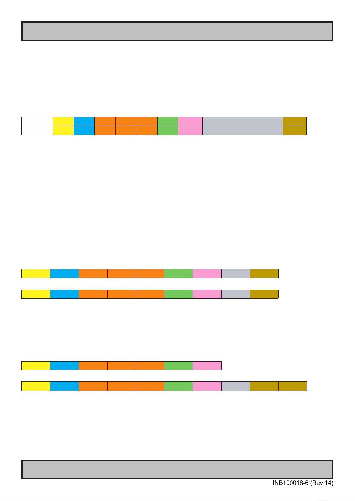
Byte # 0 1 2 3 4 5 6 7 8
0x07 0xFF 0x47 0x4D 0x42 0x01 IHCHK Buttons Minimum Brightness IDCHK
Buttons Minimum Brightness: A value describing the minimum allowed LED brightness level.
Range: [0x00-0xFF]
0x00: is "No minimum limit".
0xFF: is "Buttons will always be at max brightness".
After unit reset the value is set to: last stored value.
After microcontroller reset the value is set to: last stored value. (0x00 if no stored value)
Write:
This command will set the minimum brightness level of the button LEDs. The brightness value shall be sent as 1 byte
in the DATA eld. If the current level of the button brightness (BRL) is lower than the new GMB value, BRL level must
be raised to the GMB level.
Example:
Set GMB 0x01:
0x07 0xFF 0x47 0x4D 0x42 0x01 0x22 0x01 0xFE
ACK reply from unit:
0x06 0xFF 0x47 0x4D 0x42 0x01 0x23 0x01 0xFE
Read:
If the current BRL level is smaller than the GMB level, this command will return the GMB level. If the current BRL level
is bigger than the GMB level, this command will return the BRL level. The length of DATA shall be zero.
Example:
Get GMB:
0x07 0xFF 0x47 0x4D 0x42 0x00 0x22
ACK reply from unit:
0x06 0xFF 0x47 0x47 0x4D 0x42 0x01 0x23 0x99* 0x66
*In this example, BRL was bigger than GMB level and thus BRL was returned.
Table of contents
Other EMBRON Recording Equipment manuals


