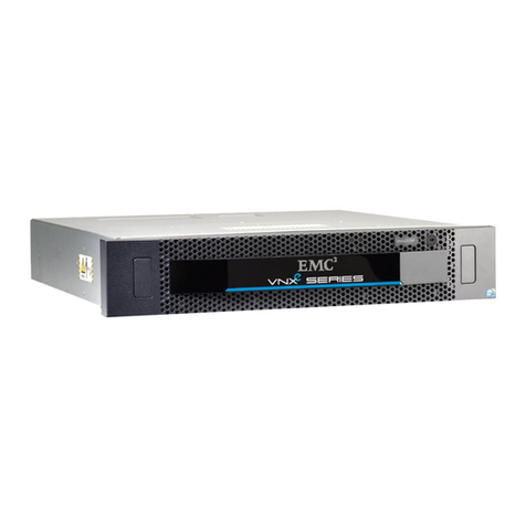
EMC CLARiiON CX4-960 User manual

EMC®CLARiiON®CX4-960
Setup Guide
P/N 300-007-009
REV. A06

Notice
Copyright © 2008-2010 EMC Corporation. All rights reserved.
Published June, 2010
EMC believes the information in this publication is accurate as of its publication date. The information is subject to
change without notice.
THE INFORMATION IN THIS PUBLICATION IS PROVIDED “AS IS.” EMC CORPORATION MAKES NO
REPRESENTATIONS OR WARRANTIES OF ANY KIND WITH RESPECT TO THE INFORMATION IN THIS
PUBLICATION, AND SPECIFICALLY DISCLAIMS IMPLIED WARRANTIES OF MERCHANTABILITY OR
FITNESS FOR A PARTICULAR PURPOSE.
Use, copying, and distribution of any EMC software described in this publication requires an applicable software
license.
For the most up-to-date regulatory document for your product line, go to the Technical Documentation and
Advisories section on EMC Powerlink.
For the most up-to-date listing of EMC product names, see EMC Corporation Trademarks on EMC.com.
All other trademarks used herein are the property of their respective owners.

1
Overview
This guide explains how to install and initialize a CX4-960 storage system in a
Windows environment. Steps include:
•Preparing your site, planning the network configuration, and verifying your
environment
•Connecting to a client and initializing the system
•Readying every server that will connect to the storage system
•Verifying the system and failover configurations
If you do not already have a Powerlink® account, we strongly recommend that you
go to http://Powerlink.EMC.com and set one up immediately. The Powerlink
website is your portal to the latest documentation and troubleshooting information,
user-customized documentation specific to your configuration, and utilities and
wizards required for the installation, such as the E-Lab™ Interoperability Navigator
and the Unisphere™ Service Manager, which replaces the Navisphere® Service
Taskbar. Use the search feature to navigate the website.
If you are installing the storage system in an environment other than Windows, (such as
Linux, AIX, HP-UX, or Solaris), visit the CLARiiON Tools page or the Technical
Documentation and Advisories sections of the EMC Powerlink website
http://Powerlink.EMC.com.

2
Preinstall - Step 1
Prepare the site
Verify that your facility has the following:
❒Adequate network support to provide each storage processor (SP) management
port with a discrete Ethernet connection and IP address.
❒Appropriate electrical wiring in place to accommodate your installation’s power
cables. To support all of the storage system’s high-availability features, you must
receive power from at least two separate circuits.
Detailed technical specifications for CX4-series systems, including AC power requirements, are
available on Powerlink.
❒A Windows workstation available on the same subnet as the storage system’s
management ports. You will use this host:
•To initialize the storage system
•As a client to launch Unisphere or Navisphere Manager. This client was
formerly referred to as the Navisphere® management station
❒CAT 5e or better Ethernet LAN cables (one per SP) for storage-system
management connections.
❒Appropriate input/output cables as recommended by your EMC representative.

3
Preinstall - Step 2
Plan network connections
With your network administrator, determine the IP addresses and network
parameters you plan to use with the storage system, and record the information on
the following worksheet. You must have this information to set up and initialize the
system.
You manage the storage system through a dedicated LAN port on each storage
processor. These ports must share a subnet with the host you use to initialize the
system. After initialization, any host on the same network and with a supported
browser can manage the system through the management ports.
To connect your storage system to an iSCSI network, you need to configure servers
and target storage systems in IP networks that use the iSCSI protocol. EMC supports
a variety of configurations, but recommends discrete networks that are dedicated to
iSCSI data traffic.
Each storage processor has at least two iSCSI ports for connecting the storage system
– either directly or through a network – to network interface cards (NICs) or iSCSI
host bus adapters (HBAs) in a server. The iSCSI data ports on the SPs are often called
targets; ports on NICs and iSCSI HBAs are iSCSI initiators.
In a server with multiple NICs or iSCSI HBAs that are connected directly to the storage
system, or that are on a dedicated iSCSI network, each initiator port must be on a separate
subnet.
Record network information for your system on the worksheet on the next page. Your
network administrator should provide most of this information. For more
information, refer to your configuration planning guide.

4
Preinstall - Step 2 continued
Plan network connections
IPv4 management port information:
SP A: IP address: ___________________ Subnet mask: _________ Gateway: _________
SP B: IP address: ___________________ Subnet mask: _________ Gateway: _________
NOTE: Do not use 128.221.1.248 through 128.221.1.255, 192.168.1.1, or 192.168.1.2 for an IPv4
IP address.
IPv6 management port information (manual configuration only):
Global prefix: _____________________ Gateway: ________________________________
Provide a username and password for your storage system.
Username: ________________________ Password: ______________________________
The storage-system serial number is located on a tag hanging from the rear of the chassis, as
shown below.
Table 1: Login information
Login information
username:
password:
storage system
serial number:
0123
0123
0123
CL4034

5
Preinstall - Step 2 continued
Plan network connections
Table 2: IPv4 addresses for iSCSI targets
SP, slot, and port Logical port
number Target Port IP address Subnet mask Gateway
SP A, slot 4, port 0
SP A, slot 4, port 1
SP B, slot 4, port 0
SP B, slot 4, port 1
SP A, slot__ , port 0
SP A, slot__ , port 1
SP B, slot__ , port 0
SP B, slot__ , port 1
SP A, slot__ , port 0
SP A, slot__ , port 1
SP B, slot__ , port 0
SP B, slot__ , port 1
SP A, slot__ , port 0
SP A, slot__ , port 1
SP B, slot__ , port 0
SP B, slot__ , port 1

6
Preinstall - Step 2 continued
Plan network connections
Table 3: IP address for each iSCSI NIC or HBA port (iSCSI initiator)
Server and port Initiator IP
address Subnet mask Default gateway

7
Preinstall - Step 3
Verify the environment
Use the E-Lab Interoperability Navigator to make sure that EMC supports all the
installed or intended components of your environment.
Verify the storage-system configuration with the E-Lab
Interoperability Navigator
1. From your web browser, go to the Powerlink site (http://Powerlink.EMC.com/)
and log in.
If you are not registered with Powerlink, you will need to register and create a
username and password.
2. Select E-Lab Interoperability Navigator from the Tools menu on the right side of
the home page.
3. Select Launch E-Lab Interoperability Navigator, and then select the Wizards tab.
4. For iSCSI, select Native iSCSI in the EMC Support Statement Results on the
right-hand side.
5. Select the Storage Array Wizard from the drop-down menu.
a. For each step of the wizard, provide the requested information based on what
you intend to attach to your storage system.
The wizard displays only those options that EMC supports.
Select FC-AL for a direct Fibre Channel connection, or FC-SW for a switch/network connection.
To display fields in the right column of a step, select an item in the left column.
b. After you have entered all the requested information, select Base
Connectivity on the right side of the page to generate a detailed configuration
report.
The report contains important information such as required hot fixes,
available patches, and the supported version of the Microsoft iSCSI initiator.
You should print a copy of the report for later use.
c. Close the report.

8
Preinstall - Step 3 continued
Verify the environment
6. Select the SOE and Software Wizard from the drop-down menu on the Wizards
tab.
7. Provide the information that the wizard requests. The wizard generates a report
listing all the PowerPath® versions compatible with your version of FLARE®
software; if your PowerPath version is not listed, you will need to upgrade to a
supported version.
A separate one-sheet document that specifies the version of FLARE software installed on your
CX4-960 shipped with the storage system.
You will install PowerPath (or a PowerPath upgrade) later in this guide. If any
other element of your projected storage-system environment does not comply
with the configuration support detailed by the E-Lab Interoperability Navigator,
correct the invalid configuration before continuing with your storage-system
installation.
8. Repeat Step 5 through Step 7 in this section for every server that will connect,
either directly or through a switch, to your new storage system.
9. Once you have verified that your environment will support the CX4-960 storage
system, continue with the next step.

9
,Install - Step 1
Install the storage-system hardware
Verify your parts
If your storage system was previously installed in a cabinet, go to "Connect the
storage-system back-end ports" (page 21).
We strongly recommend that you set up the base installation and confirm its error-free
operation before adding more, optional DAE3 enclosures.
SPE (front view)
SPE (rear view)
DAE (front view)
DAE (rear view)
Two standby power supplies
(SPS)
Power cords
1 per SPS
2 per SPE
2 per DAE
!
!
AB C D
CL4139
!!
!!
!
EXP
EXP
PRI
PRI
EXP
EXP
PRI
PRI
#
!
EXP
EXP
PRI
PRI
EXP
EXP
PRI
PRI
#
A
B
CL4108
CL4147
CL3773

10
Install - Step 1 continued
Install the storage-system hardware
Verify your parts (continued)
SPS serial (sense) cable
1 per SPS
Service cable
(save for troubleshooting)
SFP-to-HSSCD2 cables to
connect the SPE and DAEs
(2 per back end bus)
HSSDC2-to-HSSDC2 cables for
connections between DAEs
(2 per DAE).
Rail kits
(for installation in cabinet or rack)
1 per enclosure
Phillips M5 x .8 x 12.7-mm
panhead screws
Flathead screws (6)
F
12345
6789
F
12345
6789
CL3909
CL4142
CL4143
CL4058
CL4084

11
Install - Step 1 continued
Install the storage-system hardware
Install the storage-system hardware in a rack or cabinet
If your storage-system hardware is already installed in a rack or cabinet, skip to
"Connect the storage-system back-end ports" (page 21).
For detailed instructions on installing your storage system hardware, refer to the
EMC Rails and Enclosures CX4 Series Field Installation Guide (300-007-436) located on
the Powerlink website.
WARNING
!
The equipment is heavy and should be installed into a rack by two
people. To avoid personal injury and/or damage to the equipment, do
not attempt to lift and install the unit into a rack without a
mechanical lift and/or help from another person.
1. Install the standby power supply (SPS) first, at the lowest available space in the
cabinet.
The SPS is a required system component of all AC systems that allows write caching and
prevents data loss in case of a power failure.
a. Adjust the mounting tray rails to the distance between the inside edges of your
front and back NEMA channels.
Adjusting the mounting rails
Adjustment
screws
Adjustment
screws
Adjustment
screws
Adjustment
screws
SPSad
j
ustable railsEMC3460

12
Install - Step 1 continued
Install the storage-system hardware
b. Install the rail kits.
Installing the SPS rail kits
c. Install the SPS tray in the cabinet and secure it to the mounting rails
Securing the SPS tray to the mounting rails.
EMC3461
SPSadjustable rail
Right rear
Screw (2)
Alignment
pin (2)
Mounting rail
Right front
Mounting rail
Screw (1)
Rea
r
Front
EMC3463
Screws(2)
each side
Screws(2)
each side

13
Install - Step 1 continued
Install the storage-system hardware
d. From the front of the cabinet, slide the SPS units onto the tray.
Installing the SPS units onto the tray
e. Use the SPS fastening bracket to secure the SPS to the front of the rack.
Securing the fastening bracket
Rear
Front
EMC3467
Rear
Front
EMC3469
SPS
fastening bracket
Screw (8)
to SPSs

14
Install - Step 1 continued
Install the storage-system hardware
f. Tighten the captive screws on the rear of the SPS.
Securing the SPS rear
g. Install latch brackets and attach the bezel.
Installing latch brackets and attaching the bezel
EMC3480
Captive thumbscrews
CL4219

15
Install - Step 1 continued
Install the storage-system hardware
2. Install the SPE directly above the SPS tray.
a. Install the rail kits.
Installing the SPE rail kits
EMC3471
Right rear
Screw (2)
Alignment
pin (2)
Mounting rail
Alignment pins
Adjustable rail
Right front
Screw (2)
Mounting rail

16
Install - Step 1 continued
Install the storage-system hardware
b. Slide the enclosure onto the rails from the front; make sure that the cutouts in
the rear of the chassis fit into the tabs on the back of each rail.
Inserting the SPE onto the rails
c. Secure the SPE to the adjustable rails with three flathead screws on each side,
as shown. Loosen the power supply captive screw to release the handle and
gain access to the screw holes.
Securing the chassis to the cabinet
d. Secure the power supply handles into their locked position.
CL4073
Front
!
!
CL4075
Front
!
!
!

17
Install - Step 1 continued
Install the storage-system hardware
e. Assemble the adapter flange and latch bracket and attach them to the cabinet
as shown. Finally, snap on the front bezel.
f. Press the front bezel onto the latch brackets at the front of the cabinet until it
snaps into place, then lock the bezel with the key, as shown below.
3. Install the DAE-OS directly above the SPE. Be sure to match the DAE-OS and SPE
serial numbers as indicated on the packaging.
The DAE-OS is a specially marked DAE that is paired with your SPE before shipment. It
contains the OS (vault) disks, and system-specific configuration information.
CL4070
!
CL4072
CL4074
!
!

18
Install - Step 1 continued
Install the storage-system hardware
a. Install the rail kits.
Installing the DAE-OS rail kits
EMC3452
Right rear
Screw (2)
Alignment
pin (2)
Mounting rail
Alignment pins
Adjustable rail
Right front
Mounting rail
Screw (2)
Table of contents
Other EMC Network Storage Server manuals
Popular Network Storage Server manuals by other brands

IBM
IBM J15 manual

Seagate
Seagate Business Storage 1-Bay NAS quick start guide

Hewlett Packard Enterprise
Hewlett Packard Enterprise 3PAR StoreServ 8 0A Series Product End-of-Life Disassembly Instructions

Dyconn
Dyconn Quartz 5 user guide

HP
HP AK373A - StorageWorks All-in-One Storage System 1200r 5.4TB SAS Model NAS... user guide

Buffalo
Buffalo LS210D user manual