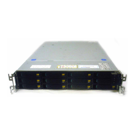
EMC2 VNX Series Owner's manual

This guide is a hardware overview guide for the EMC®VNX5400™ platform and provides
an overview of the architecture, features, and components of the VNX5400 platform. The
specific aspects of the VNX5400 platform and its major components include the front and
rear connectors and LED indicators on the 3U, 25 (2.5-inch) disk processor enclosure
(DPE), the 1U Control Station (CS), the 2U Data Mover enclosure (DME), and the 2U, 25
(2.5-inch), the 3U, 15 (2.5- or 3.5-inch), the 3U, 120 (2.5-inch), and the 4U, 60 (2.5- or
3.5-inch) disk-array enclosures (DAEs).
This guide is available online at https://mydocs.emc.com/VNX/. Go to the About VNX
section, and then select Learn about VNX hardware. Next, follow the steps in the wizard.
Topics include:
◆About this guide ....................................................................................................... 2
◆Revision history ........................................................................................................ 2
◆Product software and hardware release revisions ...................................................... 3
◆How this document is organized ............................................................................... 3
◆Related documentation............................................................................................. 4
◆Overview................................................................................................................... 5
◆VNX5400 product description ................................................................................... 6
◆Hardware features..................................................................................................... 9
◆System component description............................................................................... 13
◆Disk-array enclosures.............................................................................................. 69
◆Appendix A: Cabling.............................................................................................. 124
◆Appendix B: Field lift tool and accessory kit........................................................... 135
EMC®VNX®Family
VNX5400™
Hardware Information Guide
PN 300-014-324
Rev 05
February 25, 2015

2 EMC VNX5400 Hardware Information Guide
About this guide
About this guide
This guide is designed for personnel who install, configure, and maintain the VNX5400
platform. To use this hardware publication, you should be familiar with digital storage
equipment and cabling.
Only trained and qualified personnel should be allowed to install, replace, or service this
equipment.
Revision history
The following table presents the revision history of this document:
Revision Date Description
05 February 25, 2015 The following sections were updated:
• SP Power supply (page 31)
• Four-port 16 Gb/s optical FC I/O module
(page 50)
• 3U, 120 (2.5-inch) DAE (“3U, 120
(2.5-inch) DAE (DAE8S)” on page 90)
• Appendix B, Alum-A-Lift (“Appendix B:
Field lift tool and accessory kit” on
page 135)
Miscellaneous edits
04 July 21, 2014 The following sections were updated:
• Hardware features (“Hardware features”
on page 9)
• SP Power supply (page 31)
• Miscellaneous edits
03 January 27, 2014 The following sections were updated:
• Front view of the VNX5400 (Figure 1 on
page 7)
• Rear view of the VNX5400 (Figure 2 on
page 8)
• Hardware features (“Hardware features”
on page 9)
• Two-port 10 GbE RJ-45 Base-T I/O module
(page 24, page 56, and page 57)
• SP Power supply (page 31 and page 32)
•I/Omodule(“I/O modules” on page 44)
• Miscellaneous edits
02 October 11, 2013 Updated Table 4 on page 19.
01 July 23, 2013 First release of the
VNX5400 Hardware
Information Guide

Product software and hardware release revisions
EMC VNX5400 Hardware Information Guide 3
Product software and hardware release revisions
As part of an effort to improve its product lines, EMC periodically releases revisions of its
software and hardware. Therefore, some functions described in this document might not
be supported by all versions of the software or hardware currently in use. The product
release notes provide the most up-to-date information on product features.
Contact your EMC representative if a product does not function properly or does not
function as described in this document.
Note: This document was accurate at publication time. New versions of this document
might be released on the EMC online support website. Check the EMC online support
website to ensure that you are using the latest version of this document.
Where to get help
EMC support, product, and licensing information can be obtained as follows:
Product information — For documentation, release notes, software updates, or
information about EMC products, licensing, and service, go to the EMC Online Support
website (registration required) at:
https://Support.EMC.com
Technical support — For technical support, go to EMC online support website (registration
required) and select Support. On the Support page, you will see several options, including
one to create a service request. Note that to open a service request, you must have a valid
support agreement. Contact your EMC sales representative for details about obtaining a
valid support agreement or with questions about your account.
How this document is organized
The major sections of this guide are listed in the following table.
Table 1 Organization
Title Description
“Overview” on page 5 Describes the software and hardware features of a typical
VNX5400 along with a front view example of the VNX5400.
“VNX5400 product description”
on page 6
Describes and shows the front and rear views of a typical
VNX5400.
“System component
description” on page 13
Provides a description of the components that comprise a
VNX5400. Along with a description, illustrations of each
component are also shown.
“General” on page 13 Describes and illustrates the front of a DPE and the components
that comprise it.
“Control Station front view” on
page 18
Describes and illustrates the front view of the Control Station
used in the VNX5400.

4 EMC VNX5400 Hardware Information Guide
Related documentation
EMC provides the ability to create step-by-step planning, installation, and maintenance
instructions tailored to your environment. To create VNX customized documentation, go
to: https://mydocs.emc.com/VNX/.
To download a PDF copy of the desired publication, go to the following sections:
◆For hardware-related guides, go to About VNX, then select Learn about VNX hardware.
Next, follow the steps in the wizard.
◆For technical specifications, go to About VNX, then select View technical
specifications. Next, follow the steps in the wizard.
◆For installation, adding, or replacing tasks, go to VNX tasks section, then select the
appropriate heading. For example, to download a PDF copy of the
VNX5400 Block
Installation Guide
, go to Install VNX, and follow the steps in the wizard.
◆For server-related tasks, go to the VNX Server tasks section, then select the
appropriate heading. For example, to download a PDF copy of adding or replacing
server hardware, go to VNX Server tasks, and select Add or replace server hardware.
Next, follow the steps in the wizard.
Title Description
“Data Mover enclosure front
view” on page 21
Describes and illustrates the front view of a DME and the
components that comprise it.
“DPE rear view” on page 23 Describes and illustrates the rear of a DPE and the components
that comprise it.
“Control Station rear view” on
page 36
Describes and illustrates the rear view of the Control Station
used in the VNX5400.
“Data Mover enclosure rear
view” on page 41
Describes and illustrates the rear of a DME and the components
that comprise it.
“I/O modules” on page 44 Describes and illustrates the types of I/O modules supported in
the VNX5400.
“Disk-array enclosures” on
page 69
Describes and illustrates the three types of DAEs available for
the VNX5400.
“Appendix A: Cabling” on
page 124
Describes the types of DAE cabling available for the Block and
File/Unified VNX5400 platform. The cabling can be either
stacked or interleaved depending on your specific
requirements.
“Appendix B: Field lift tool and
accessory kit” on page 135
Describes the type of portable (mechanical) lift and accessory
kit used for lifting hardware components into a rack.
Table 1 Organization (continued)

Safety warnings
EMC VNX5400 Hardware Information Guide 5
Safety warnings
Safety warnings appear throughout this publication in procedures that, if performed
incorrectly, might harm you or damage the equipment. A caution or warning symbol
precedes each safety statement. The safety warnings provide safety guidelines that you
should follow when working with any equipment that connects to electrical power or
telephone wiring.
IMPORTANT
The portable (mechanical) lift tool described in “Appendix B: Field lift tool and accessory
kit” on page 135 is recommended as a safety precaution when lifting EMC components
into an EMC or customer-provided rack. As described in the appendix, many of the EMC
components are too heavy to be lifted by one person or in some cases by two persons. As
a result, this portable (mechanical) lift tool is a necessary safety requirement, especially
when lifting EMC components like the 3U, 120 and the 4U, 60 DAEs.
Overview
The EMC VNX series implements a modular architecture that integrates components for
Block, File, and Object with concurrent support for native NAS, iSCSI, Fiber Channel, and
Fibre Channel over Ethernet (FCoE) protocols. The VNX series is based on Intel Xeon-based
PCI Express 3.0 processors and delivers File (NAS) functionality via two to eight Data
Movers and Block (iSCSI, FCoE, and FC) storage via dual storage processors using a full
6-Gb/s SAS disk drive topology. The VNX Series is targeted at the entry-level to
high-end/large-capacity storage environments that require advanced features, flexibility
and configurability. The VNX Series provides significant advancements in efficiency,
simplicity, and performance.
Benefits include:
◆Support for File (CIFS and NFS), Block (FC, iSCSI & FCoE) and Object
◆Simple conversions when starting with a VNX Series Block only platform by simply
adding File services or starting with File only and adding Block services
◆Support for both block and file auto-tiering with Fully Automated Storage Tiering
(FAST) for Virtual Pools (VP - FAST VP)
◆Unified replication with RecoverPoint support for both file and block data
◆Updated unified management with Unisphere now delivering a more cohesive unified
user experience
Offering Block and File services, Block services only, or File services only, the VNX5400
platform is an entry-level storage platform. For a quick look at the VNX5400 platform
hardware features, see Table 2, “Block and File VNX5400 platform hardware feature quick
reference,” on page 9.
In a Block services configuration, the VNX5400 platform supports a 3U DPE and four types
of DAEs. The 3U DPE supported is a 25 drive 2.5-inch disk 3U enclosure (or DPE9). The
DAEs supported are a 25 drive 2.5-inch disk 2U enclosure (or DAE5S), a 15 drive 2.5- or
3.5-inch disk 3U enclosure (or DAE6S), a 120 drive 2.5-inch disk 3U enclosure (or DAE8S),

6 EMC VNX5400 Hardware Information Guide
VNX5400 product description
and a 60 drive 2.5- or 3.5-inch disk 4U enclosure (or DAE7S). Expansion of up to up to
nine 2U, 25 DAEs (a maximum of 225, 2.5-inch disk drives), up to fifteen 3U, 15 DAEs (a
maximum of 225, 2.5- or 3.5-inch disk drives), up to one 3U, 120 DAE (a maximum of 120,
2.5-inch disk drives), or up three 4U, 60 DAEs (a maximum of 180, 2.5- or 3.5-inch disk
drives) is supported.
Note: When the 3U, 120 or 4U, 60 DAEs are implemented in the VNX5400 platform, the
40U Dense rack is required because of the depth of the 3U and 4U DAEs.
IMPORTANT
When calculating the number of disk drives for your Block, File, and Unified services
VNX5400 platform, the DPE is included in the total drive slot quantity of 250 drives. If the
total drive slot quantity exceeds 250, you will not be able to add another DAE. Refer to the
“Disk-array enclosures” section on page 69 for more information about the available
expansion DAEs for the VNX5400 platform.
In a File services or a Unified services configuration (Figure 1 on page 7), the VNX5400
platform supports a 3U DPE, from one to two 1U Control Stations (CS0 and CS1), one to
two 2U Data Mover enclosures having one to four Data Movers1, and four types of DAEs.
The 3U DPE supported is a 25 drive 2.5-inch disk 3U enclosure (or DPE9). The DAEs
supported are a 25 drive 2.5-inch disk 2U enclosure (or DAE5S), a 15 drive 2.5- or 3.5-inch
disk 3U enclosure (or DAE6S), a 120 drive 2.5-inch disk 3U enclosure (or DAE8S), and a
60 drive 2.5- or 3.5-inch disk 4U enclosure (or DAE7S). Expansion of up to up to nine 2U,
25 DAEs (a maximum of 225, 2.5-inch disk drives), up to fifteen 3U, 15 DAEs (a maximum
of 225, 2.5- or 3.5-inch disk drives), up to one 3U, 120 DAE (a maximum of 120, 2.5-inch
disk drives), or up three 4U, 60 DAEs (a maximum of 180, 2.5- or 3.5-inch disk drives) is
supported.
Note: The Block or the File and Unified services configuration of the VNX5400 platform can
have a mix of DAE types to conform to your specific requirements. In other words, you can
have a mix of 2U DAEs, 3U DAEs, and 4U DAEs in the same environment so as long as the
VNX5400 platform does not have no more than the supported amount of 250 disk drives.
VNX5400 product description
This section shows examples of the front and rear views of a VNX5400 platform.
Note: A fully configured VNX5400 platform with a 3U DPE of 25 (2.5-inch disk drives) can
include up to nine 2U, 25 DAEs (a maximum of 225, 2.5-inch disk drives), up to fifteen 3U,
15 DAEs (a maximum of 225, 2.5- or 3.5-inch disk drives), up to one 3U, 120 DAE (a
maximum of 120 2.5-inch disk drives), or up to three 4U, 60 DAEs (a maximum of 180,
2.5- or 3.5-inch disk drives). As a result, by using the DAEs described above in this
paragraph, the maximum disk drive capacity would become 250, 250, 145, or 205,
respectively.
1. The term Data Mover is used throughout this guide. The term Data Mover is also referred to as a
blade. These terms are interchangeable and mean the same.

VNX5400 product description
EMC VNX5400 Hardware Information Guide 7
For additional details on the locations of orderable parts, and their part number labels,
refer to the
VNX5400 Parts Location Guide
.
Front view
Figure 1 shows an example of the front view of a File/Unified VNX5400 platform having a
3U, 25 (2.5-inch) disk drive DPE, two 2U Data Mover enclosures with four Data Movers,
and two 1U Control Stations (one optional).
Note: The example shown in Figure 1 does not show any DAEs.
Figure 1 Example of a File/Unified VNX5400 platform (front view)
1
G
b
E
01
X4
6Gb SAS
6Gb SAS
23
1
0
1
G
b
E
01
X4
6Gb SAS
6Gb SAS
23
1
0
0
Will Make the Array Unusable
Caution:Array Software on drives 0-3. Removing or relocating them
AB
SP
SP
AC AC AC AC
3U, 25 (2.5-inch)
disk processor
enclosure
Data Mover
enclosure 0
Control Station 0
Control Station 1
(optional)
AC AC AC AC
Data Mover
enclosure 1
VNX-000940

8 EMC VNX5400 Hardware Information Guide
VNX5400 product description
Rear view
Figure 2 shows an example of the rear view of a File/Unified VNX5400 platform having a
3U DPE showing two storage processors (SP A and B), two 2U Data Mover enclosures with
four Data Movers, and two 1U Control Stations (one optional).
Note: The example shown in Figure 2 does not show any DAEs.
Figure 2 Example of a File/Unified VNX5400 platform (rear view)
Note: Figure 1 on page 7 and Figure 2 are examples of a File/Unified VNX5400 platform
(front and rear views) without any DAEs. These figures are for illustrative purposes only.
Control Station 1
(optional)
Data Mover
enclosure 0
Disk processor
enclosure
Control Station 0
0123
0123
AC
DC
!
10
10
X4
AC
DC
!
X4 X4
X4
0123
0123
B MGMT
MGMT
B
CS A
12
MGMT
IOIO
B MGMT
MGMT
B
CS A
12
MGMT
IOIO
Data Mover
enclosure 1
0123
0123
Data Mover 5
Data Mover 2Data Mover 3
Data Mover 4
VNX-000941

VNX5400 product description
EMC VNX5400 Hardware Information Guide 9
Hardware features
Contained in a 9U architecture, the File/Unified VNX5400 platform weighs approximately
182.82 lb (82.925 kg) fully loaded2without I/O modules and DAEs. With the 3U DPE
having the deepest dimension within the cabinet, the File/Unified VNX5400 without DAEs
measures (9U) 12.25 inches high x 17.62 inches wide x 24.77 inches deep (31.11 cm x
44.76 cm x 69.92 cm). Between the front and rear of the enclosure, a midplane distributes
power and signals to all the enclosure components. On the front of the VNX5400 DPE, the
CPU modules, cooling fan modules, and disk drives plug directly into the midplane
connections. On the rear of the VNX5400 DPE, the battery backup unit (BBU) modules, the
base modules, power supply modules, management modules, and I/O modules plug
directly into the midplane connections.
Note: The previously mentioned dimensions are approximate and do not include any I/O
modules, DAEs, or the cabinet enclosure.
For more information about the weight and dimensions of a VNX5400 platform, go to
https://mydocs.emc.com/VNX/ and go to the About VNX section, and then select View
technical specifications. Next, follow the steps in the wizard.
Configured for AC-input power, the VNX5400 platform includes the following hardware
features:
Note: A DC powered VNX5400 model is also available.
2. A fully loaded VNX5400 (without any DAEs) includes two 1U Control Stations, one 3U DPE (with
two SPs), and two 2U Data Mover enclosure with four Data Movers. In this fully loaded File/Unified
VNX5400 platform, the 3U DPE (with two SPs) can have 25 (2.5-inch) disk drives. Separately, the
25 (2.5-inch) drives weigh 13.5 lb (6.13 kg).
Table 2 Block and File VNX5400 platform hardware feature quick reference
Minimum
form
factor
Maximum
# of
drives
Drive
types
Block File
Config.
I/O
slots
per SP
Built-in
I/O ports
per SP SPs
System
memory
per SP Protocols
Config.
I/O slots
per DM DMs
System
memory
per DM Protocols
3U w/out
optional
CS,
DMEs,
and DAEs
250 6-Gb/s
2.5 or
3.5 in.
SAS
and
2.5 or
3.5 in.
Flash
41Two 4x
lane BE2
6-Gb/s
mini-SAS
ports
2 16 GB FC, iSCSI,
and FCoE
3 1 to 436 GB NFS,
CIFS,
and
pNFS4
1. For the type and number of Ultraflex I/O modules supported in the SP, refer to the I/O module section on page “Storage processor I/O module
types” on page 46.
2. BE = back end
3. For the type and number of Ultraflex I/O modules supported in the DM, refer to the I/O module section on page “Data Mover I/O module types” on
page 60.
4. pNFS = parallel-NFS

10 EMC VNX5400 Hardware Information Guide
VNX5400 product description
◆One 3U DPE:
• On the front of the VNX5400, the 3U DPE (Figure 2 on page 8) has two SPs (SP A
and B). Each SP consists of:
– One disk drive carrier type; the 3U, 25 (2.5-inch) disk drive carrier (Figure 3 on
page 15). Two types of disk drives are supported in this carrier: Serial
attached-SCSI (SAS) and Flash
– Four dual cooling fan packs (see “Storage processor dual fan pack (cooling
module)” on page 14 for more information) or packs (eight fans total)
Note: The dual cooling fan pack is secured with push-tabs on the left and right
sides of each pack.
– One CPU module with an Intel Xeon 4-core 1.8-GHz processor facilitating
Simultaneous Multi-Threading (SMT).
– Eight Double Data Rate Three (DDR3) synchronous dynamic RAM (SDRAM) slots
supporting up to 16 GB of SDRAM per CPU module or SP using 4 or 8 GB DIMMs
– Three LEDs; power on, fault, and unsafe to remove
Note: Each CPU is secured with a push tab/pop out latch.
• On the rear of the VNX5400, the 3U DPE (Figure 2 on page 8) has two SPs (SP A and
B). Each SP consists of:
– One battery backup unit (BBU) providing back-up power for the SP and the disk
drives allowing for the flushing (data cacheing) of the vault drives whenever an
AC or DC input power loss to the storage system occurs (see “Battery backup
unit” on page 26 for more information).
Note: The BBU module is secured with a push-pull type of latch.
– One base module featuring two integrated 4x lane 6-Gb/s mini-SAS HD
(encryption capable) back-end ports (labeled 1and 0, respectively).
Note: The base module is secured with a screw-type of latch (see “Base
module” on page 26 for more information).
– One management module (see “Storage processor management module” on
page page 32 for more information) featuring:
a.) One RS-232/EIA 232 serial (up to 115 K baud) service laptop (micro DB-9)
port
b.) One RS-232/EIA 232 serial SPS management (micro DB-9) port
c.) One 10/100/1000 LAN network management (RJ-45) port
d.) One 10/100/1000 LAN service (RJ-45) port
Note: The management module is secured with a latch handle (labeled MGMT).

VNX5400 product description
EMC VNX5400 Hardware Information Guide 11
– One power supply module (hot-swappable) featuring (see “Storage processor
power supply module” on page 31 for more information):
Note: Three types of power supplies are supported in the VNX5400 storage
system. Two AC type power supplies and one DC type power supply. For more
information on the power supply types, see “Storage processor power supply
module” on page 31 and the
VNX5400 Parts Location Guide
for more
information.
a.) One recessed power plug
b.) Three LEDs (labeled with !for fault, DC and AC); the labels on the LEDs are
printed upside down.
Note: The power supply is secured with a pull latch and handle.
– Four PCI Gen 3, 8x lane I/O module slots (A1 – A4 and B1 – B4) are available for
use, supporting:
Note: The maximum number of I/O modules for the VNX5400 is 4 per SP. Any
combination of the following I/O modules up to four per SP.
a.) Four-port 8-Gb/s FC optical (running at 2, 4, or 8 Gb/s); labeled 8 GbE Fibre
on the latch handle
Four-port 16-Gb/s FC optical (running at 4, 8, or 16 Gb/s); labeled
16 GbE Fibre v1 on the latch handle
b.) Four-port 1-Gb/s Base-T iSCSI I/O module; labeled 1 GbE iSCSI/TOE on the
latch handle
c.) Two-port 10-Gb/s optical or active Twinax5; labeled 10 GbE v3 on the latch
handle
d.) Two-port 10-Gb/s RJ45 Base-T iSCSI/IP; labeled 10 GbE Base-T on the latch
handle
Note: This I/O module is not supported when the VNX5400 storage system is
using the low powered (800 W, 100-240 V) power supply (see “Storage processor
power supply module” on page 31 and the
VNX5400 Parts Location Guide
for
more information).
e.) Two-port 10-Gb/s Fibre Channel over Ethernet (FCoE); labeled 10 GbE/FCoE
on the latch handle
◆One to two 2U DMEs:
• On the front, the DME has one to two Data Movers (DMs). Each DM consists of:
– One CPU module (see “CPU” on page 22 for more information)
– Two power supply/cooling modules
• On the rear, the DME has one to two Data Movers. Each DM consists of:
– One management module (see “Data Mover management module” on page 41
for more information) featuring:
a.) One RS-232/EIA 232 serial (up to 115 K baud) service laptop (micro DB-9)
port

12 EMC VNX5400 Hardware Information Guide
VNX5400 product description
b.) Three 10/100/1000 LAN network management (RJ-45) ports
Note: The management module is secured with a latch handle (labeled MGMT).
– One CPU module consisting of one Intel Xeon 4-core 2.13-GHz processor. The
CPU modules in the DME contain the power, fault, and unsafe-to-remove LEDs
(see “CPU” on page 22 for more information).
– Six DDR3 synchronous dynamic RAM (SDRAM) slots supporting up to 6 GB per
CPU module using 2 or 4 GB DIMMs
– Three PCI Gen 2, 8x lane I/O module slots (0 – 2) available for use, supporting:
Note: The maximum number of I/O modules for the VNX5400 is three per DM.
One FC I/O module and up to two other I/O modules. Any combination of these
I/O modules must be the same for both Data Movers.
a.) One Fibre Channel (FC) I/O module with a:
– Four-port 8-Gb/s optical (running at 2, 4, or 8 Gb/s); in slot 0 only;
labeled 8 GbE Fibre on the latch handle
b.) One or two of the following network I/O modules in any combination:
– Two-port 10-Gb/s optical or active Twinax; labeled 10 GbE v3 on the
latch handle
– Four-port 1-Gb/s copper; labeled 1 GbE on the latch handle
– Two-port 10-Gb/s RJ45 Base-T iSCSI/IP; labeled 10 GbE Base-T on the
latch handle
◆One to two 1U Control Stations
◆A fully configured VNX5400 platform with a 3U DPE of 25 (2.5-inch disk drives) can
include up to nine 2U, 25 DAEs (a maximum of 225, 2.5-inch disk drives), up to fifteen
3U, 15 DAEs (a maximum of 225, 2.5- or 3.5-inch disk drives), up to one 3U, 120
DAEs3(a maximum of 120 2.5-inch disk drives), or up to three 4U, 60 DAEs3(a
maximum of 180, 2.5- or 3.5-inch disk drives). As a result, by using the DAEs
described above in this paragraph, the maximum disk drive capacity would become
250, 250, 145, or 205, respectively.
IMPORTANT
When calculating the number of disk drives for your VNX5400 platform, the DPE is
included in the total drive slot quantity of 250 drives. If the total drive slot quantity
exceeds 250, you will not be able to add another DAE. Refer to the “Disk-array
enclosures” section on page 69 for more information about the available expansion
DAEs for the VNX5400 platform.
◆Any required cables including LAN cables, modem cables, and serial DB-9 cable.
◆Mounting rails with hardware
◆Front bezel with VNX5400 badge
3. When using a 3U, 120 or 4U, 60 DAE, a 40U Dense rack is required.

System component description
EMC VNX5400 Hardware Information Guide 13
System component description
This section describes the VNX5400 platform components. Included in this section are
illustrations and descriptions of the front and rear connectors as well as the LED
indicators.
Note: In the following sections, the illustrations and corresponding tables describe these
individual components. These descriptions are for illustrative purposes only.
Installing, replacing, and removing faulted hardware components
Separate documents provide instructions for installing, replacing, and removing hardware
components in the VNX5400 platform. For more information, refer to the respective
document for the correct procedure. These documents are available online at
https://mydocs.emc.com/VNX/ and go to VNX tasks, then select Add VNX hardware. Next,
follow the steps in the wizard.
Example:
To replace a BBU in the DPE9 of a VNX5400, go to the
Replacing a battery backup unit in a
disk processor enclosure
document for the correct procedures to replace a BBU module in
a DPE9 disk processor enclosure. This procedure is available online at
https://mydocs.emc.com/VNX/ and go to VNX tasks, then select Add VNX hardware. Next,
follow the steps in the wizard.
VNX5400 front view
As previously described, a Block VNX5400 platform is made up of a 3U DPE while a
File/Unified VNX5400 platform is made up of a 3U DPE, one to two 2U DMEs, and one to
two 1U Control Stations (one optional). The following sections describe the front view
(Figure 3 on page 15) of the VNX5400 platform components.
General
On the front of the VNX5400 platform, the DPE comprises the following components:
◆Drive carrier
◆Disk drives
◆Midplane
◆Storage processor (SP) CPU
◆Storage processor (SP) dual fan pack (cooling module)
◆EMI shielding
Drive carrier
The disk drive carriers are metal and plastic assemblies that provide smooth, reliable
contact with the enclosure slot guides and midplane connectors. Each carrier has a
handle with a latch and spring clips. The latch holds the disk drive in place to ensure
proper connection with the midplane. Disk drive activity/fault LEDs are integrated into the
carrier. The “3U, 25 (2.5-inch) disk processor enclosure” section on page 14 provides
more information.

14 EMC VNX5400 Hardware Information Guide
System component description
Disk drives
Each disk drive consists of one disk drive in a carrier. You can visually distinguish
between disk drive types by their different latch and handle mechanisms and by type,
capacity, and speed labels on each disk drive. You can add or remove a disk drive while
the 3U DPE is powered up, but you should exercise special care when removing modules
while they are in use. Disk drives are extremely sensitive electronic components.
IMPORTANT
When calculating the number of drives for your VNX5400 platform, the DPE is included in
the total drive slot quantity of 250 drives. If the total drive slot quantity exceeds 250, you
will not be able to add another DAE. Refer to the “Disk-array enclosures” section on
page 69 for more information about the available expansion DAEs for the VNX5400
platform.
Midplane
A midplane separates the front-facing disk drives from the rear-facing SPs. It distributes
power and signals to all components in the enclosure. SPs and disk drives plug directly
into the midplane.
Storage processor CPU
The storage process (SP) CPU is the intelligent component of the 3U disk processor
enclosure (DPE). Acting as the control center, each SP CPU includes status LEDs. The “3U,
25 (2.5-inch) disk processor enclosure” section on this page provides more information.
Storage processor dual fan pack (cooling module)
When viewed from the front, each SP CPU module has two dual fan packs located on the
bottom of the SP. Each dual fan pack includes an amber fault LED. Latches on the fan pack
lock it into place to ensure proper connection. The “Storage processor dual fan pack
(cooling module)” section on page 17 provides more information.
EMI shielding
EMI compliance requires a properly installed electromagnetic interference (EMI) shield in
front of the DPE disk drives. When installed in cabinets that include a front door, the DPE
includes a simple EMI shield. Other installations require a front bezel that has a locking
latch and integrated EMI shield. You must remove the bezel/shield to remove and install
the disk drives.
3U, 25 (2.5-inch) disk processor enclosure
The 25 (2.5-inch) disk processer enclosure (DPE) includes the following:
◆2.5-inch 6-Gb/s SAS or Flash disk drives (hot-swappable)
◆Status LEDs
◆CPU latches
◆Fan packs and latches

System component description
EMC VNX5400 Hardware Information Guide 15
Figure 3 on page 15 shows the location of the disk drives, fan packs, CPU latches, and
status LEDs.
Figure 3 Example of a VNX5400 platform 3U, 25 DPE (front view)
1Example of a 2.5-inch 6-Gb/s SAS disk
drive
7DPE fault LED (amber)
2Dual fan pack fault LED (amber) 8DPE power status LED (blue)
3Dual fan pack (two dual packs per SP) 9Disk drive fault LED (amber)
4Dual fan pack pull tab (latch, left
side), two places
10 Disk drive status/activity (blue)
5See Detail Detail SP power/status LED (Green, on); SP fault
LED (amber/blue, various modes - see
“VNX5400 platform 3U, 25 DPE, SP, and
disk drive status LEDs” on page 16 for
more information); Unsafe to remove LED
(white); CPU push/pop latch (two places)
6Dual fan pack pull tab (latch, right
side), two places
1
G
b
E
01
X4
6Gb SAS
6Gb SAS
23
1
0
1
G
b
E
01
X4
6Gb SAS
6Gb SAS
23
1
0
0
Will Make the Array Unusable
Caution: Array Software on drives 0-3. Removing or relocating them
24
AB
SP
SP
0
3
6
1
4
5
7
8
Blue/amber
fault
Green on
White
Unsafe to remove
910
Detail
2
0 1 0 1
VNX-000520

16 EMC VNX5400 Hardware Information Guide
System component description
Table 3 describes the VNX5400 platform 3U, 25 DPE, SP, and disk drive status LEDs.
Table 3 VNX5400 platform 3U, 25 DPE, SP, and disk drive status LEDs
LED Color State Description
Dual fan pack fault
(see location 2)
Amber On Fan fault
— Off Fan operating normally
DPE fault (see location 7) Amber On DPE faulted
— Off DPE not faulted
DPE power (see location 8) Green On Powering and powered up
Off Powered down
Disk drive fault
(see location 9)
Amber On Fault has occurred
— Off No fault has occurred
Disk drive on/activity
(see location 10)
Blue On Powering and powered up
Blinking Disk drive activity
SP fault LED, behavior
during normal boot (see
Detail)
Amber On (steady) SP fault
Blinks once every
4 seconds
Executing BIOS
Blinks once every
second
Executing Post
Blinks four times
a second
Post starting operating system
Blue Blinks once every
4 seconds
Operating system booted
Blinks once every
second
SEP start in progress
Blinks four times
a second
SEP start completed
— Off Operating system ready for input
SP fault LED, during
degraded boot (see Detail)
Amber Blinks once every
4 seconds
Executing BIOS
Blinks once every
second
Executing Post
Blinks four times
a second
Post starting operating system
Blue Blinks once every
4 seconds
Operating system booted
On Degraded mode
SP fault LED, during faults
(see Detail)
— Off Powered down
Amber On Fault has occurred

System component description
EMC VNX5400 Hardware Information Guide 17
Storage processor dual fan pack (cooling module)
As previously described, the SP dual fan pack cooling module provides cooling to the SP
CPU. Four dual-pack fans are provided; two dual-pack fans per SP. Each fan pack includes
an amber fault LED (see Figure 4).
Figure 4 Example of the fan fault LED
SP fault LED, during faults
(see Detail) continued
Amber Blinks once every
2 seconds
NMI reset pushed; blinking will
continue until SP reboots and
enters power on sequence.
Blinks at 1, 3, 3,
and 1 times a
second
Memory problem
Blue On Fault has occurred
SP unsafe to remove (see
Detail)
White On The SP peer has a panic or
rebooted with the cache
performance mode enabled. The
SP is holding valid cache in
memory.
The SP is currently flashing the
BIOS/Post firmware or updating
the resume PROMs.
The SP is currently dumping the
cache data to the vault.
— Off The SP can be safely removed for
service.
SP power status (see Detail) Green On SP is powered up normally
— Off SP is powered off
Table 3 VNX5400 platform 3U, 25 DPE, SP, and disk drive status LEDs (continued)
LED Color State Description
CL5184

18 EMC VNX5400 Hardware Information Guide
System component description
You have two minutes to remove the faulted fan pack (cooling module) and install a
replacement before the SP shuts down. For more information, refer to the
Replacing a
Storage Processor Fan
module
procedure for the correct steps to take before and during
removal of a fan pack. This procedure is available online at:
https://mydocs.emc.com/VNX/ and go to VNX tasks, select Replace VNX Hardware. Next,
follow the steps in the wizard.
Control Station front view
On the front, viewing from left to right, the File/Unified VNX5400 platform 1U Control
Station includes the following components:
◆One DVD-ROM drive
◆Two USB 2.0 connectors (not used)
◆Front control panel with various buttons and status LEDs
◆Four hot-swappable SATA hard drive bays
Figure 5 shows the orientation of these components.
Figure 5 Example of a VNX5400 platform Control Station (front view)
DVD-ROM drive USB 2.0 connectors Control panel
Hard drives
VNX-000521

System component description
EMC VNX5400 Hardware Information Guide 19
Control Station front panel
Figure 6 shows the location of the File/Unified VNX5400 platform 1U Control Station front
panel.
Figure 6 VNX5400 platform Control Station front panel
Table 4 describes the Control Station front panel.
VNX-000549
Front
45
ID
ID
1
2
3
4
31 2
678910
Table 4 Control Station LEDs and push buttons
LED Color State Description
Onboard (integrated) LAN 2
and 4 (see locations 1 and
2, respectively)
Green On NIC link/no access
Blinking NIC link/LAN access
—Off Idle
Internal hard drive activity
(see location 3)
Green Blinking Hard drive access
— Off No hard drive activity, no fault
Power (see location 4)
Note: For correct power up
and down procedures, go to
https://mydocs.emc.com/
VNX/ and go to the VNX
tasks section, then select
Power up and down VNX.
Next, follow the steps in the
wizard.
Green On Power on/system loaded and
ready
Blinking Sleep mode
—Off Poweroff

20 EMC VNX5400 Hardware Information Guide
System component description
Status/fault (see location 5) Green On Powered on; status ok
Blinking Powered on; degraded.
Redundancy lost, such as power
supply or fan failure, or
predictive power supply failure.
Amber On Critical fault: Voltage, thermal, or
power fault; CPU missing;
insufficient power unit
redundancy resource offset
asserted.
Blinking Non-critical failure: Critical
temperature/voltage
— Off Power off: System unplugged
Powered on: System powered off
and in standby, no prior
degradation/critical state.
Reset button
(see location 6)
— — Allows you to reset the CS. Same
as turning the power off and then
on again. Data loss will occur
unless you have saved the data.
The reset button would be used
when a program error occurs and
has caused the CS to freeze.
Pressing the reset button
performs a cold restart (reboot)
which goes through the initial
start-up stages including
memory check.
Onboard (integrated) LAN 1
and 3 (see locations 7 and
8, respectively)
Green On NIC link/no access
Blinking NIC link/LAN access
—Off Idle
NMI button (see location 9) — — Not used
ID button with LED
(see location 10)
Green On Powered on
Table 4 Control Station LEDs and push buttons (continued)
LED Color State Description
Other manuals for VNX Series
5
This manual suits for next models
1
Table of contents
Other EMC2 Computer Hardware manuals
Popular Computer Hardware manuals by other brands

NAD
NAD MDC2 BluOS-D Mounting instructions

Cypress Semiconductor
Cypress Semiconductor CY7C1380DV25 Specification sheet

Renesas
Renesas R0E436640CFG20 user manual

Lenovo
Lenovo ThinkServer TD200x Hardware Maintenance Manual

Econ Technologies
Econ Technologies SoundMeister installation manual

ST
ST STR91 Series Application note