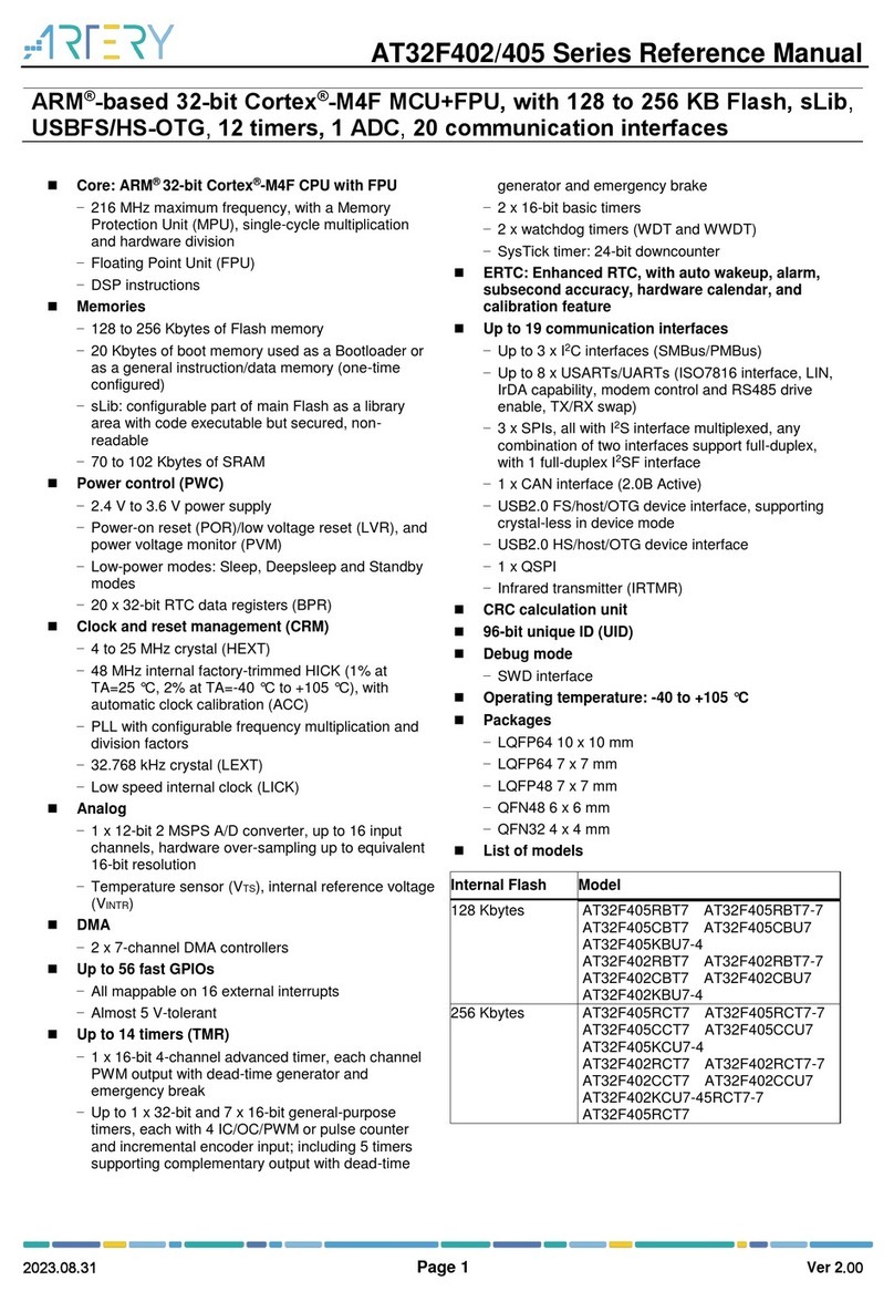
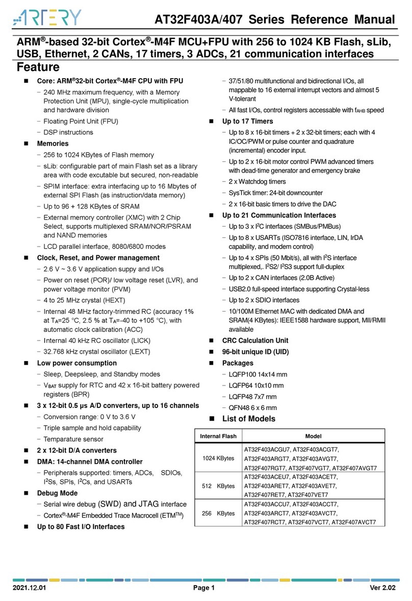
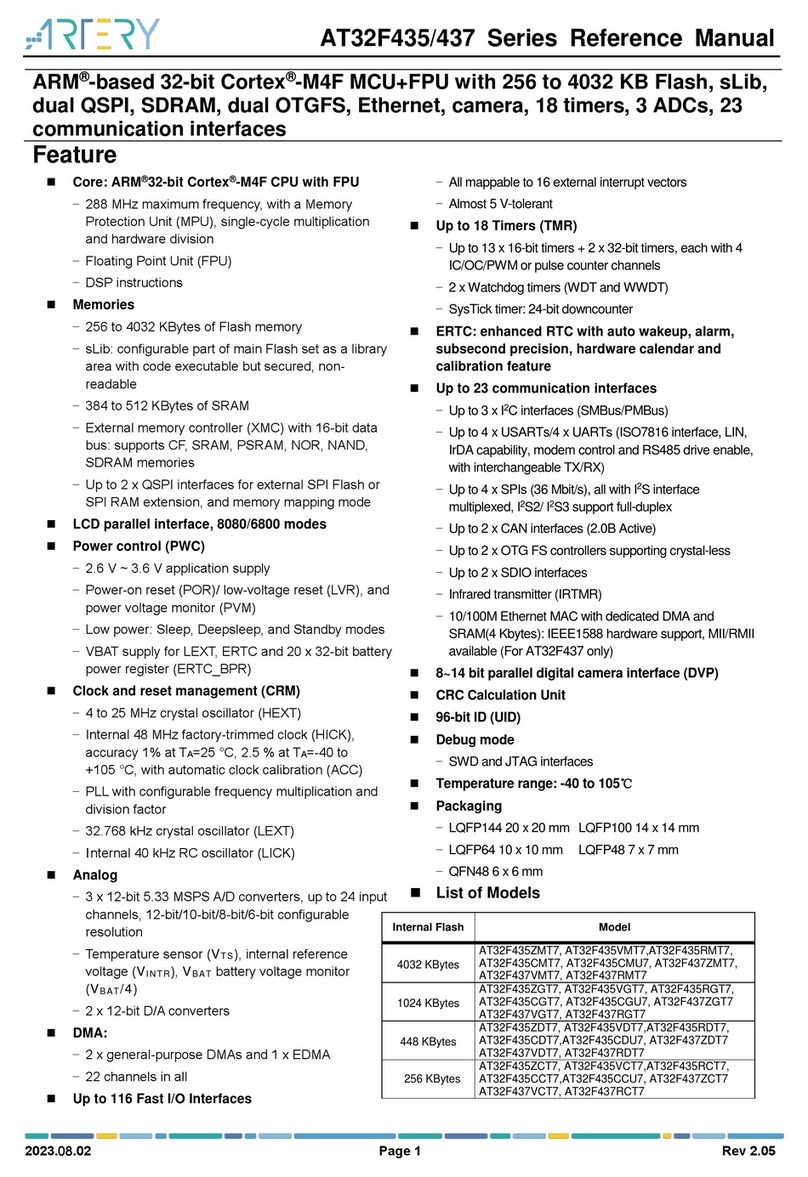
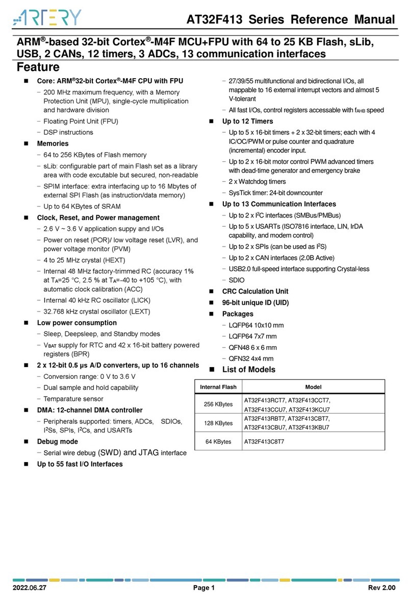
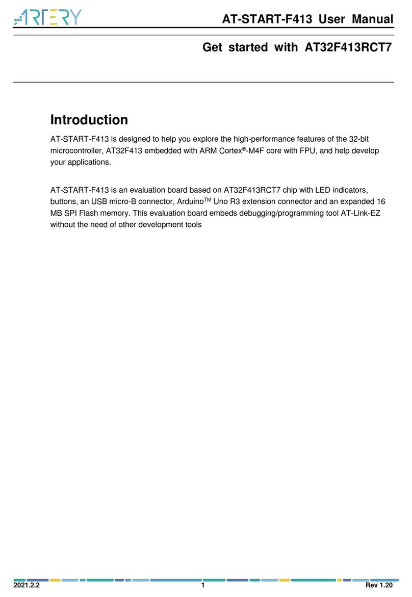
ARTERY AT32 MCU CAN User manual

AT32 MCU CAN Quick Start Guide
2022.7.19 1 Ver 2.0.1
AN0095
Application Note
AT32 MCU CAN Quick Start Guide
Introduction
The CAN (Controller Area Network) is a distributed serial communication protocol which realizes real-
time and reliable data communication between nodes, compliant with the CAN 2.0 specification (2.0A
and 2.0B). This application note introduces CAN protocol, AT32 MCU CAN application flow and
examples of AT32 MCU CAN application.
Note: The corresponding code in this application note is developed on the basis of V2.x.x BSP
provided by Artery. For other versions of BSP, please pay attention to the differences in usage.
Applicable products:
Part number
AT32Fxx
AT32Lxx

AT32 MCU CAN Quick Start Guide
2022.7.19 2 Ver 2.0.1
Contents
1Introduction to CAN............................................................................................... 6
2CAN protocol.......................................................................................................... 7
2.1 CAN bus topology ....................................................................................................7
2.2 CAN bus physical layer features............................................................................... 7
2.3 Frame type............................................................................................................... 8
2.4 Frame structure...................................................................................................... 10
2.5 Bit stuffing...............................................................................................................10
2.6 Bit format.................................................................................................................11
2.7 Synchronization mechanism................................................................................... 12
2.8 Arbitration mechanism............................................................................................ 13
2.9 CAN error handling mechanism.............................................................................. 14
2.9.1 Error type....................................................................................................................14
2.9.2 Error state...................................................................................................................15
3AT32 CAN.............................................................................................................. 16
3.1 Function overview ..................................................................................................16
3.2 Message transmission............................................................................................16
3.3 Message reception.................................................................................................17
3.4 Filter....................................................................................................................... 19
3.5 CAN baud rate and sample point............................................................................21
3.5.1 Baud rate formula.......................................................................................................21
3.5.2 Sample point formula .................................................................................................21
3.5.3 Baud rate configuration tool.......................................................................................22
4Application case 1: CAN communication in normal mode ............................. 23
4.1 Function .................................................................................................................23
4.2 Resources.............................................................................................................. 23
4.3 Software design...................................................................................................... 23
4.4 Test result...............................................................................................................27

AT32 MCU CAN Quick Start Guide
2022.7.19 3 Ver 2.0.1
5Application case 2: CAN receive filter............................................................... 28
5.1 Function .................................................................................................................28
5.2 Resources.............................................................................................................. 28
5.3 Software design...................................................................................................... 28
5.4 Test result...............................................................................................................35
6Application case 3: CAN debugging in loopback mode.................................. 36
6.1 Function .................................................................................................................36
6.2 Resources.............................................................................................................. 36
6.3 Software design...................................................................................................... 36
6.4 Test result...............................................................................................................40
7Revision history................................................................................................... 41

AT32 MCU CAN Quick Start Guide
2022.7.19 4 Ver 2.0.1
List of tables
Table 1 CAN frame types.....................................................................................................................8
Table 2 Description of bit segments................................................................................................... 11
Table 3 Sample point settings............................................................................................................21
Table 4 Document revision history.....................................................................................................41

AT32 MCU CAN Quick Start Guide
2022.7.19 5 Ver 2.0.1
List of figures
Figure 1 CAN bus topology..................................................................................................................7
Figure 2 CAN bus level characteristics................................................................................................8
Figure 3 CAN frame structure..............................................................................................................9
Figure 4 CAN standard data frame....................................................................................................10
Figure 5 Normal bit timing..................................................................................................................12
Figure 6 Resynchronization jump......................................................................................................13
Figure 7 Arbitration mechanism.........................................................................................................14
Figure 8 CAN node error states.........................................................................................................15
Figure 9AT32 CAN function overview...............................................................................................16
Figure 10 Message transmission process.........................................................................................17
Figure 11 Message reception process...............................................................................................19
Figure 12 32-bit identifier mask mode...............................................................................................20
Figure 13 32-bit identifier list mode ...................................................................................................20
Figure 14 16-bit identifier mask mode...............................................................................................20
Figure 15 16-bit identifier list mode ...................................................................................................20
Figure 16 CAN BitRate configuration tool .........................................................................................22
Figure 17 CAN level converter schematics diagram.........................................................................23
Figure 18 CAN level converter schematics diagram.........................................................................28
Figure 19 CAN loopback mode .........................................................................................................36

AT32 MCU CAN Quick Start Guide
2022.7.19 6 Ver 2.0.1
1 Introduction to CAN
The Controller Area Network (CAN) is designed to efficiently process a large amount of messages
with minimum CPU usage. It is a serial bus protocol created in 1986 by the German company
BOSCH and ISO standardized with ISO11898 and ISO11519, which gain popularity in the
automotive network domain in Europe. It has been recognized for high performance and reliability
and widely used in industrial automation, ships, medical facilities and industrial equipment, etc.
Features of CAN protocol:
Multi-master control
When the bus is idle, all nodes can start sending messages. When multiple nodes start
sending at the same time, the bus proceeds arbitration according to the identifier (ID), and
the one with the lowest ID (highest priority) wins and gets the right to send while all other
nodes (with lower priority) switch to a receiving mode. It should be noted that ID does not
the node address but the priority of message to be sent.
Flexibility
As mentioned, there is no address information of nodes on the CAN bus; therefore, adding
or removing a node does not affect the hardware and software of other nodes on the CAN
bus.
High reliability
CAN protocol features are error detection, error notification, fault confinement and error
handling. Every node on the CAN bus can detect an error (error detection) in a message.
If any error is found, the discovering node will transmit an error frame to notify other nodes
(error notification). Each node has an error counter internally that accumulates error count
value every time an error is detected. When the accumulative error count value of one
node is greater than 256, this fault node is disconnected from the CAN bus to avoid
affecting other nodes (fault confinement). If the node detects an error when sending a
message, the erroneous message will be retransmitted after the fault is cleared (error
handling).
Fast and long-range communication
The rate can reach 1 Mbps (communication distance < 40m) and communication distance
can reach 10km (rate < 5Kbps).
Multiple nodes
The number of nodes on a CAN bus is not limited theoretically, but the ultimate number is
determined by the bus time delay and electrical load. Lowering or increasing the
transmission rate can correspondingly increase or decrease the number of nodes.
With these features, the CAN is suitable for interconnection of industrial process monitoring devices
and is recognized as one of the most ideal fieldbuses for industrial applications. The CAN protocol
is ISO standardized with ISO11898 and ISO11519, in which ISO11898 is the CAN high-speed
communication standard with a communication speed of 125 Kbps~1 Mbps and ISO11519-2 is a
low-speed communication standard with a communication rate of 125 Kbps or less. In this
application note, the ISO11898 standard is adopted and the communication rate is 1 Mbps.
AT32 MCU CAN Quick Start Guide
2022.7.19 7 Ver 2.0.1
2 CAN protocol
This section mainly introduces the CAN bus topology, characteristics of physical layers, CAN frame
types, frame structure, bit stuffing mechanism, bit format, synchronization mechanism, arbitration
mechanism and error handling mechanism. For more details on CAN protocol, refer to BOSCH CAN
specification.
2.1 CAN bus topology
As shown in Figure 1, the CAN bus consists of CANH and CANL lines. Each node is connected to
CAN bus through a short branch line, and can transmit and receive data equally. In addition, there
is a120 Ωterminal resistor at each end of CAN bus for impedance matching to reduce reflection.
Figure 1 CAN bus topology
CANnode n
CANnode 2
CANnode 1
MCU
CAN
controller
CAN
transceiver
CAN
TX
CAN
RX
120Ω
120Ω
...
CANH
CANL
CANH
CANL
CANH
CANL
... ...
2.2 CAN bus physical layer features
As shown in Figure 2, the dominant level corresponds to logical “0” (voltage difference between
CANH and CANL is about 2.5 V) and the recessive level corresponds to logical “1” (voltage
difference between CANH and CANL is 0 V). On the CAN bus, the dominant level always overrides
a recessive level, which means that the CAN bus level will be dominant is any number of nodes in
the network output a dominant level, and the CAN bus level will only be recessive when all nodes in
the network output a recessive level.

AT32 MCU CAN Quick Start Guide
2022.7.19 8 Ver 2.0.1
Figure 2 CAN bus level characteristics
1
2
3
4
5
[V]
CAN bus physical
layer signal
CAN bus logical
value 1
0
Dominant
level
Recessive
level Recessive
level
CANH line
CANL line
2.3 Frame type
There are five types of frames in CAN protocol, as shown in Table 1. The data frame and remote
frame are transmitted and received by users, while the error frame, overload frame and inter frame
are transmitted by hardware of nodes on CAN bus according to the specific status, which is
unnecessary to be or cannot be controlled by users.
Table 1 CAN frame types
Frame type
Description
Data frame
It carries data from transmitting node to receiving node.
Remote frame
It is sent by a node to request the transmission of a data frame with the
same ID by another node.
Error frame
It is sent when error information is detected on any node.
Overload frame
It requests a delay between the preceding and subsequent data frame (or
remote frames).
Inter frame
It is also known as inter-frame space, which is used to separate the above
four types of frames.
The structure of each frame type is shown in Figure 3.

AT32 MCU CAN Quick Start Guide
2022.7.19 9 Ver 2.0.1
Figure 3 CAN frame structure
Inter-frame
space Data frame (standard identifier)
44 + 8* N
Arbitration field
12
ID
6
Control field Data field
8* NCRC field
16
CRC
Ack field
27
EOF
DLC
SOF
RTR
IDE
r0
ACK
Data frame ( extended identifier)
64 + 8* N
Inter-frame
space or
overload frame
ID EOF
DLC
SOF
RTR
IDE
r0
ACK
Arbitration field
12 Arbitration field
20 Control field
68 * N
Data field CRC field
16
CRC
Ack field
27
SRR
r1
Remote frame
44
Inter-frame
space or
overload frame
Arbitration field
12
ID
6
Control field CRC field
16
CRC
DLC
Ack field
27
EOF
ACK
RTR
r0
IDE
SOF
Data frame
or remote
frame Error frame
Inter-frame
space or
overload frame
Error flag Error echo Error delimiter
6 6 8
Data frame or
remote frame
Intermission Suspend
transmission Bus idle
3 8
Any frame
End of frame or
error delimiter or
overload delimiter Overload frame Inter-frame space
or error frame
Overload
flag Overload
echo Overload
delimiter
6 6 8
Notes:
0 <= N <= 8
SOF = Start of frame
ID = Identifier
RTR = Remote transmission request
IDE = Identifier extension bit
r0 = Reserved bit
DLC = Data length code
CRC = Cyclic redundancy code
Error flag: 6 dominant bits if error
active; else, 6 recessive bits.
Suspend transmission: Only applies to
error passive node.
EOF = End of frame
ACK = Acknowledge bit
Inter-frame
space or
overload frame
Inter-frame space
Inter-frame
space
Inter-frame
space

AT32 MCU CAN Quick Start Guide
2022.7.19 10 Ver 2.0.1
2.4 Frame structure
This section mainly introduces standard data frame. For other frame types, refer to Figure 3 for
better understanding.
The CAN data frame is composed of seven fields as below:
SOF (Start of frame): It is dominant of 1-bit. The CAN bus level is recessive when the CAN bus is
in an idle state; therefore, the dominant SOF bit marks the start of a message on the node.
Arbitration: It indicates the frame priority and contains message identifier and frame type
(data/remote frame).
Control: It indicates the number of bytes, identifier format (standard/extended) and the reserved bit.
Data: Up to 8 bytes of data can be sent in one message (data length is determined by the DLC in
the control field).
CRC (cyclic redundancy check): The transmitter calculates a check sum from the transmitted bits
(stuff bit not included) and provides the result within the frame in the CRC field. The receivers use
the same polynomial to calculate the check sum from the bits as seen on the bus-lines. The self-
calculated check sum is compared with the received on. In case of a mismatch, the receiving node
sends an error frame. If it matches, the frame is regarded as correctly received and then sent to the
ACK field.
ACK (acknowledge): It contains the ACK SLOT and ACK DELIMITER. The transmitting node is
always recessive in the ACK field. If no error is detected on the receiving node during receiving
process, the ACK bit outputs 1-bit dominant level to notify the transmitting node that this frame is
correctly received.
EOF (End of frame): It indicates the end of a data frame, and it is recessive of 7-bit.
Figure 4 CAN standard data frame
Start of
frame identifier
Remote trans
request
Identifier
extension bit
Reserved
bit Data
length
code Data CRC
delimiter ACK
bit ACK
delimiter End of frame
CRC calculation
CAN bit stuffing
Inter-frame space Data frame (standard identifier)
44 + 8* N
Arbitration field
12
ID
6
Control field Data field
8* N
CRC field
16
CRC
Ack field
27
EOF
DLC
SOF
RTR
IDE
r0
ACK
Inter-frame space or
overload frame
2.5 Bit stuffing
Since the CAN bus contains CANH/CANL lines only, without a CLK line for synchronization, it
implements synchronization directly through the signal in data stream (refer to 2.7 Synchronization
Mechanism). In addition, the bit stuffing mechanism is introduced to deal with the possible condition
of no edge in data stream.
Every time 5 consecutive bits at the same level are found in the bit sequence sent on the bus, the
CAN controller in the transmitting device(s) automatically inserts a stuff bit at the opposite value. For

AT32 MCU CAN Quick Start Guide
2022.7.19 11 Ver 2.0.1
example, the original data stream is “0000000111110001…” and the data stream sent to CAN bus
after bit stuffing is “000001001111100001…”, in which the underlined bits are stuff bits.
Bit stuffing is added from the SOF to CRC field (CRC delimiter not included), as shown in Figure 4.
2.6 Bit format
One bit of AT32 CAN can be divided into the following 3 segments:
Synchronization segment (SYNC_SEG)
Bit segment 1, including PROP_SEG and PHASE_SEG1 in CAN standard, marked as
BSEG1.
Bit segment 2, i.e., PHASE_SEG2 in CAN standard, marked as BSEG2.
These segments consists of the smallest time unit (Time Quantum, Tq).
One bit is divided into three segments, and each segment consists of several Tq, which is called bit
timing.
The number of Tq per bit / bit segment and bit timing can be set as required. Users can set the bit
timing and Tq length to set CAN baud rate and sample point.
Table 2 lists each segment and configurable Tq ofAT32 CAN.
Table 2 Description of bit segments
Segment (CAN
standard)
Segment (AT32
CAN)
Description
Tq
Synchronization
segment
(SYNC_SEG)
Synchronization
segment
(SYNC_SEG)
It is used to synchronize all nodes
connected to the CAN bus, and a signal
edge is expected within this segment.
1Tq
Propagation
segment
(PROP SEG)
Bit segment 1
(BSEG1)
It is used to compensate for the physical
delay times within the network, and its
length is twice these delay times to
compensate for input comparator and
output driver.
1~16T
q
Phase segment 1
(PHASE SEG1)
It is used to compensate for phase error
in the edge phase, and it may be
lengthened or shortened through
resynchronization jump.
Phase segment 2
(PHASE SEG2)
Bit segment 2
(BSEG2)
1~8Tq
As shown in Figure 5, one bit consists of a synchronization segment, bit segment 1 and bit segment
2. The sample point, i.e., the sampling point of receiving node, is at the junction of BSEG1 and
BSEG2.

AT32 MCU CAN Quick Start Guide
2022.7.19 12 Ver 2.0.1
Figure 5 Normal bit timing
SYNC_SEG BSEG1BSEG2
Nomal Bit Timing
Sample Translate
tBSEG1tBSEG2
tSYNC_SEG
2.7 Synchronization mechanism
Hard synchronization
After a hard synchronization, the bit time is restarted with the end of synchronization segment. Thus
hard synchronization forces the edge which has caused the hard synchronization to lie within the
synchronization segment of the restarted bit time, as shown in Figure 6.
Resynchronization jump width
Resynchronization leads to lengthening of bit segment 1 or shortening of bit segment 2. The
maximum bit lengthening and shortening are given by the resynchronization jump width (which
should be set to 1~4 Tq).
As shown in Figure 6,
When a falling edge is detected on BSEG1, the BSEG1 lengthens for Tdelay and the current bit
lengthens for Tdelay, in which the Tdelay<= resynchronization jump width.
When a falling edge is detected on BSEG2, the BSEG2 shortens for Tadvance and the current bit
shortens for Tadvance, in which the Tadvance<= resynchronization jump width.

AT32 MCU CAN Quick Start Guide
2022.7.19 13 Ver 2.0.1
Figure 6 Resynchronization jump
SYNC_SEG BSEG1 BSEG2
1bit
Transmitting
node
Sample point
Ideal falling edge
Transmitting
node Sample point
Falling edge on BSEG1
SYNC_SEG BSEG1 BSEG2
Transmitting
node Sample
point
Falling edge on BSEG2
Tadvance
SYNC_SEG BSEG1 BSEG2
1bit
tdelay
1bit Start of the next bit
tdelay
2.8 Arbitration mechanism
Whenever the bus is free, any node may start to transmit the message. If two or mode nodes start
transmitting messages at the same time, the bus access conflict occurs, which can be resolved by
the bitwise arbitration using the identifier. The mechanism of the arbitration guarantees that neither
information nor time is lost. If a data frame and a remote frame with the same identifier are initiated
at the same time, the data frame prevails over to the remote frame. During the arbitration, every
transmitter compares the level of the bit transmitted with the level that is monitored on the bus. If
these levels are equal, the node may continue to the send. When a recessive level is sent, but a
dominant level is monitored, the node has lost arbitration and must withdraw without sending any
further bits.
As shown in Figure 7, note 1 and node 2 transmit a message at the same time with the same
identifier; from the red mark, node 1 starts transmitting recessive level “1” and node 2 starts
transmitting dominant level “0”. At this time, node 2 wins the arbitration and keeps transmission, and
the bus level is the same as that of node 2; while node 1 loses the arbitration and switches to a
receiving mode in the next bit, with the subsequent transmitting pins remains at a recessive level.

AT32 MCU CAN Quick Start Guide
2022.7.19 14 Ver 2.0.1
Figure 7 Arbitration mechanism
Node 1
Node 2
Bus level
Arbitration lost
2.9 CAN error handling mechanism
2.9.1 Error type
There are five types of error in CAN protocol.
Bit error
CAN nodes transmitting a message to the bus also monitor the bus and compare the
transmitted level bit by bit with the corresponding level on the bus.A bit error is detected when
the transmitted bit level differs from the monitored bus level.AT32 CAN bit error is classified
into dominant bit error (transmitted bit is dominant while recessive bit is monitored) and
recessive bit error (transmitted bit is recessive while dominant bit is monitored).A bit error may
occur when CAN nodes are in a transmitting mode.
However, there are exceptions that a dominant bit on the bus will not lead to a bit error when a
recessive bit is transmitted during arbitration or during the ACK slot, and a node sending a
passive error frame and detecting a dominant bit will not interpret this as a bit error.
Stuff error
A stuff error occurs whenever 6 consecutive bits of equal value are detected on the bus (in the
bit stuffing region shown in Figure 4). A stuff error may occur when CAN nodes are in a
receiving mode.
CRC error
CRC sequence contains the CRC checksum calculated by the transmitter (the receiver uses
the same polynomial to calculate the checksum). If the calculated CRC is different from the
received CRC, then the receiver signals it as CRC error. A CRC error may occur when CAN
nodes are in a receiving mode.
Form error
A form error is detected when a fixed format field contains one or more dominant bits. For
example, if a dominant bit is detected in the CRC delimiter /ACK delimiter, it is a form error.
There is an exception that the dominant bit during the last bit at the end of frame of the
receivers is not considered as a frame error.A form error may occur when the CAN node is in
a receiving mode.
Acknowledgment error
As long as the monitored during the ACK SLOT bit is not "dominant", then the transmitter will
detect an error response (acknowledgment error).An acknowledgment error may occur when

AT32 MCU CAN Quick Start Guide
2022.7.19 15 Ver 2.0.1
CAN node is in a transmitting mode.
2.9.2 Error state
When an error is detected on the CAN node, the transmit error counter (TEC[7:0]) /receive error
counter (REC[7:0]) is increased by 1 or 8 (refer to BOSCH CAN protocol for details) according to
the specific error state and type. After each time of correct transmission/receiving of a message, the
TEC/REC is decreased by 1. Therefore, the TEC/REC value indicates the stability of CAN node and
network. Depending on the TEC/REC value, a node can be in one of three states:
Error active
In this state, node can participate in all CAN activity and raise “Active Error Flag” (6 dominant
bits) when detecting errors.As shown in Figure 8, when TEC<128 and REC<128, a CAN node
enters into error active state.
Error passive
In this state, node can participate in data/remote frame receiving and transmitting, and raise
“Passive Error Flag” (6 recessive bits) when detecting errors. As shown in Figure 8, when
255≥TEC>128 and 255≥REC>128, a CAN node enters into error passive state.
Bus-off
In this state, node is switched off from the CAN bus and neither sends nor receives frames.As
shown in Figure 8, when TEC>255, a CAN node enters into bus-off state.
AT32 CAN node bus-off management:AT32 CAN node recovers from bus-off state in the
following conditions:
1) When theAEBOEN bit of CAN_MCTRL register is set to 0, the software requests to enter
and then exit freeze mode, and then the CAN node waits for 128 occurrences of 11
consecutive recessive bits (detected on RX) in communication mode.
2) WhenAEBOEN bit is set to 1, the CAN node waits for 128 occurrences of 11 consecutive
recessive bits (detected on RX) in communication mode.
Figure 8 CAN node error states
Error Active Error Passive
Bus off
TEC or REC>127
TEC and REC<128
TEC>255
128 occurrences of
11 consecutive
recessive bits

AT32 MCU CAN Quick Start Guide
2022.7.19 16 Ver 2.0.1
3 AT32 CAN
AT32 CAN is compliant with the CAN 2.0 specification (2.0A and 2.0B), with some functions and
configurable options added based on the compatible standard CAN protocol. The main differences
between CAN 2.0Aand 2.0B are as follows: CAN 2.0A only supports 11-bit IDs (i.e., standard
frames) while CAN 2.0B supports 11-bit/29-bit IDs (i.e., standard and extended frames).
This section mainly introduces the AT32 CAN structure and application method, AT32 CAN
communication process including transmission, receiving, message filtering, baud rate and sample
point settings. Refer to Reference Manual for details about error management and interrupt
management, etc.
3.1 Function overview
As the number of nodes in the CAN network and the number of messages grows, an enhanced
filtering mechanism is required to handle all types of messages in order to reduce the processing
time of message reception. One FIFO scheme is used to ensure that the CPU can concentrate on
application tasks for a long period of time without the loss of messages. In the meantime, the priority
order of the messages to be transmitted is configured by hardware. Based on the above mentioned
conditions, AT32 CAN controller provides 28 identifier filter banks (configurable bit width), two
receive FIFOs (storing 3 complete messages each) and three transmit mailboxes with their transmit
priority order defined by the transmit scheduler. The message transmitting and receiving process is
totally managed by hardware, without occupying CPU.
Figure 9 AT32 CAN function overview
Receive
FIFO [1:0]
Mail
box
0
Mail
box
1
Mail
box
228 filter banks Bit timing control
RX/TX
Send arbitrationEmail [2:0]
Receive
FIFO [1:0]
Mail
box
0
Mail
box
1
Mail
box
228 filter banks RX/TX
Bit timing control
Send arbitrationEmail [2:0]
CAN
CAN 1
CAN 2
3.2 Message transmission
The message transmission process is shown in Figure 10, including the following steps.
Steps 1~3 are performed by the user, and steps 4~7 are completed by hardware automatically.
1) Program selects one empty mailbox (send mailbox empty flag by setting TMxEF=1);
2) Write the message to be sent into the corresponding empty mailbox, and the message content
includes ID, frame type, data length and transmit data;
3) Request to send: Set TMSR=1 in the CAN_TMIx register;
4) Mailbox pending (wait until the priority is given);
5) Schedule transmission (wait until the CAN bus becomes free);

AT32 MCU CAN Quick Start Guide
2022.7.19 17 Ver 2.0.1
6) Transmit;
7) Mailbox becomes empty.
Note: Steps 1~7 are brief transmission procedures, and Figure 10 also demonstrates transmission
cancelled, transmission failed, and automatic retransmission enabled / disenabled. Refer to
message transmission in the Reference Manual for details.
Figure 10 shows the following flag bits and operation bits:
TMxTCF bit: Transmission complete flag (request to send/abort)
TMxTSF bit: Transmission success flag
TMxEF bit: Transmit mailbox empty flag
TMSR bit: Request to send
TMxCT bit:Abort sending
PRSFEN: Disable automatic retransmission (automatic retransmission disabled when PRSFEN =1;
automatic retransmission enabled when PRSFEN=0)
Figure 10 Message transmission process
Idle
TMxTCF=X
TMxTSF=X
TMxEF=1
Idle
TMxTCF=1
TMxTSF=0
TMxEF=1
Idle
TMxTCF=1
TMxTSF=1
TMxEF=1
Scheduled
TMxTCF=0
TMxTSF=0
TMxEF=0
Pending
TMxTCF=0
TMxTSF=0
TMxEF=0
Transmit
TMxTCF=0
TMxTSF=0
TMxEF=0
TMSR=1
TMxCT=1
Transmission
failed* PRSFEN
Transmission
success
CAN bus =
IDLE
Transmission
failed*PRSFEN
Highest
priority
Mailbox priority
not given
TMxCT=1
3.3 Message reception
The message reception process is shown in Figure 11 (empty and pending_1), including the
following steps.
1) FIFO empty;
2) Valid message received;
3) Enter into “pending_1” state (there is one valid message in FIFO);
4) Read valid message: Read CAN_RFIx, CAN_RFCx, CAN_RFDTLx and CAN_RFDTHx

AT32 MCU CAN Quick Start Guide
2022.7.19 18 Ver 2.0.1
registers;
5) Release mailbox: Set RFxR=1 in the CAN_RFx register.
Note: Steps 4~3 are performed by the user, and steps 1~3 are completed by hardware
automatically.
Valid message:
When a message is received correctly (no error occurs in the whole EOF field) and has passed
identifier filtering, it is regarded as a valid message.
If the user does not participate in the message receiving process (i.e., neither read the valid
message nor release mailbox), the hardware completes the following process:
1) Valid message received;
2) Enter into “pending_1” state (there is one valid message in FIFO);
3) Valid message received;
4) Enter into “pending_2”state (there are two valid messages in FIFO);
5) Valid message received;
6) Enter into “pending_3”state (there are three valid messages in FIFO);
7) Valid message received;
8) Enter into “overflow” state (there are three valid messages in FIFO and one message is lost,
and the overflow flag is set).
Figure 11 shows the following flag bits and operation bits:
RFxMN bit: Number of valid messages in FIFO (range: 0~3)
RFxOF bit: Overflow flag
RFxR bit: Release mailbox

AT32 MCU CAN Quick Start Guide
2022.7.19 19 Ver 2.0.1
Figure 11 Message reception process
Empty
RFxMN=0×00
RFxOF=0
Pending_1
RFxMN=0×01
RFxOF=0
Pending_3
RFxMN=0×11
RFxOF=0
Pending_2
RFxMN=0×10
RFxOF=0
Overflow
RFxMN=0×11
RFxOF=1
Valid
message
received
Valid message
received
Valid message
received
Release
mailbox
RFxR=1
Valid message
received
Valid message
received
Release
mailbox
RFxR=1
Release
mailbox
RFxR=1
Release
mailbox
RFxR=1
3.4 Filter
In CAN protocol, the message ID does not represent the node address but is related to the
message content. Therefore, the transmitter broadcasts the message to all receiver, and the node
determines whether or not this message is required by software according to the ID value. If
required, this message is stored in the receive FIFO, which can be obtained by users by reading the
receive mailbox register; if not required, this message is discarded, without intervention by software.
To meet these requirements, AT32 CAN controller provides 28 identifier filter banks (28 filter banks
(0~27) for theAT32F435 series, and 14 filter banks (0~13) for theAT32F403Aseries; refer to the
reference manual of the corresponding series) to receive messages required by software. The
filtering process does not require software operation after the required ID is configured by the user.
Filter bit width
Each filter bank has two 32-bit registers (CAN_FiFB1 and CAN_FiFB2). The filter bit width can be
configured as two 16 bits or one 32 bits, depending on the FBWSELx bit in the CAN_FBWCFG

AT32 MCU CAN Quick Start Guide
2022.7.19 20 Ver 2.0.1
register.
One 32-bit filter register CAN_FiFBx includes the SID[10:0], EID[17:0], IDT and RTR bits.
Two 16-bit filter register CAN_FiFBx includes the SID[10:0], IDT, RTR and EID[17:15] bits.
Filtering mode
The filter can be configured in identifier mask mode or in identifier list mode by setting the FMSELx
bit in the CAN_FMCFG register. The mask mode is used to specify which bits must match the pre-
programmed identifiers, and which bits do not need. In identifier list mode, the identifier must match
the pre-programmed identifier.
The two modes can be used in conjunction with filter width to deliver four filtering modes below:
Figure 12 32-bit identifier mask mode
CAN_FiFB1[31:21] CAN_FiFB1[20:3]
CAN_FiFB2[31:21] CAN_FiFB2[20:3]
CAN_FiFB1
[2:0]
CAN_FiFB2
[2:0]
SID[10:0] EID[17:0] IDT RTR 0
ID
Mask
Mapping
Figure 13 32-bit identifier list mode
CAN_FiFB1[20:3] CAN_FiFB1
[2:0]
CAN_FiFB2[20:3] CAN_FiFB2
[2:0]
IDT RTR 0
CAN_FiFB1[31:21]
CAN_FiFB2[31:21]
SID[10:0] EID[17:0]
ID
ID
Mapping
Figure 14 16-bit identifier mask mode
CAN_FiFB1[15:5] CAN_FiFB1[4:0]
CAN_FiFB1[31:21] CAN_FiFB1[20:16]
CAN_FiFB2[15:5] CAN_FiFB2[4:0]
CAN_FiFB2[31:21] CAN_FiFB2[20:16]
SID[10:0] RTR EID[17:15]IDT
ID
Mask
ID
Mask
Mapping
Figure 15 16-bit identifier list mode
CAN_FiFB1[15:8] CAN_FiFB1[7:0]
CAN_FiFB1[31:24] CAN_FiFB1[23:16]
CAN_FiFB2[15:8] CAN_FiFB2[7:0]
CAN_FiFB2[31:24] CAN_FiFB2[23:16]
SID[10:0] RTR EID[17:15]IDT
ID
ID
ID
ID
Mapping
For details about filter match number and priority rules, refer to the reference manual of the
corresponding series. The filter configuration process is detailed in the example of CAN acceptance
filter application.
Table of contents
Other ARTERY Computer Hardware manuals

ARTERY
ARTERY AT32F423 Series User manual

ARTERY
ARTERY AT32F402 Series User manual

ARTERY
ARTERY AT32F425 Series User manual

ARTERY
ARTERY AT-START-F413 User manual

ARTERY
ARTERY AT32F423 Series User manual

ARTERY
ARTERY AT32F421 Series User manual

ARTERY
ARTERY AT32F421 Series User manual

ARTERY
ARTERY AT32F425 Series User manual

ARTERY
ARTERY AT32F435ZDT7 User manual

ARTERY
ARTERY AT32A403A Series User manual