Emcee SR 30 E User manual

SR 30 E
1004156
Planetary Winches
PURPOSE OF THE MANUAL
This manual has been compiled by the Manufacturer to provide information on the safe transport, handling,
installation, maintenance and repair of winches
Failure to adhere to the information provided herein may result in risk to personal health and safety, and may incur
economic damages.
The documentation must be stored by a person with the correct authority and must always be made available
for consultation. A copy of the users manual can best be kept close the working area of the winch.
The manual reflects the state of the art at the time of commercialization of the winch. The Manufacturer
reserves the right to modify, supplement and improve the manual, without the present publication being for that
reason considered inadequate.
Particularly significant sections of the manual and important specifications are highlighted by symbols whose
meanings are given below.
DANGER
-
WARNING
This symbol indicates situations of serious danger which, if ignored, may result in serious
risks to the health and safety of personnel.
CAUTION
-
ATTENTION
This symbol indicates the need to adopt specific precautions to avoid risks to the health and
safety of personnel and possible economic damages.
IMPORTANT
This symbol indicates import and technical information.
The instructions indicated on a grey background next to theses symbols refer exclusively to
equipment conforming to the “ATEX“ Directive94/9/EC.
The operations highlighted by these symbols must be carried out by qualified professionals
specially trained in the safety requirements for zones characterized by potentially explosive
atmospheres.
Failure to observe these instructions may result in serious risks to personal and
environmental safety.

General Manual Electric Winches with UMPH rope-English Rev.1.1 – 10-12-2014
Intellectual property
Winch models, drawings and engineering are of our exclusive property. It is expressly forbidden to copy, use or
hand over to third parties such information without a specific written permission.
Warranty
EMCÉ warrants to the original user its winches to be free of defects in material and workmanship for a period of
one year from the date of purchase. EMCÉ will repair, without cost, any product found to be defective, including
parts and labor charges, or at its option, will replace such products or refund the purchase price less a
reasonable allowance for depreciation, in exchange for the product.
If any product proves defective within its original one year warranty period, it should be returned to any
authorized EMCÉ dealer, transportation prepaid with proof of purchase or winch data sheet / test certificate.
This warranty does not apply to products which EMCÉ has determined to have been misused or abused,
improperly maintained by the purchaser; or where the malfunction or defect can be attributed to the use of non-
genuine EMCÉ parts.
EMCÉ makes no other warranty, and all implied warranties including any warranty of merchantability or fitness
for a particular purpose are limited to the duration of the expressed warranty period as set forth above. EMCÉ´s
maximum liability is limited to the purchase price of the product and in no event shall EMCÉ be liable for any
consequential, indirect, incidental, or special damages of any nature arising from the sale or use of the product,
whether based on contract, tort, or otherwise.
With a missing TAG plate the product is not conform the current CE machine construction
standards and warranty will expire.
The following information is required to ensure reliable delivery of spare parts:
Fabrication number (Fabr. No.).............................................................................(on factory TAG plate)
Product type...........................................................................................................(on factory TAG plate)
Spare part number.............................................................................................................. (from manual)
Additional information such as type and/or description of the parts..................................(from manual)
EMCÉ cannot guarantee a smooth delivery of spare parts unless the above information is not
fully submitted. If the TAG plate is removed or damaged, contact your dealer or supplier.
EMCÉ do reserve the right to modify and upgrade the winches they fabricate at any moment and without
advance notice and will not be liable for any difference between winch features and the specifications of present
use and maintenance manual.
Contact the EMCÉ technical department in case extra information is required about for example maintenance
and repair. This users manual is made with great care. EMCÉ cannot be put responsible for errors in this
publication or for the impact of this.
This users manual is written by EMCÉ in Voorhout.

General Manual Electric Winches with UMPH rope-English Rev.1.1 – 10-12-2014
CONTENT
1.
GENERAL SAFETY INSTRUCTIONS
2.
INTRODUCTION
2.1
GENERAL
2.2
SPECIFICATIONS
2.3
OPTIONS
3.
GENERAL DESCRIPTION OF WINCHES
3.1
GENERAL OPERATING PRINCIPLE
3.2
DESCRIPTION OF THE ELECTRIC CIRCUIT
3.3
SAFETY INFORMATION
4.
INSTALLATION
4.1
INSTALLATION
4.2
GEARBOX LUBRICATION
4.3
ROPE
4.4
START UP SEQUENCE
5.
WORKING WITH THE MACHINE
5.1
START, NORMAL OPERATION and STOP
5.2
INSPECTIONS
5.3
TROUBLE SHOOTING
6.
MAINTENANCE
6.1
LUBRICATION
6.2
GEARBOX OIL CHECKS AND CHANGES
6.3
SLEWING GEARS
6.4
BOLT TIGHTENING CHECK
6.5
BRAKE CLEANING
ANNEX I: PRODUCT DATASHEET AND CERTIFICATES
ANNEX II: TECHNICAL INFORMATION COMPONENTS
ANNEX III: DRAWINGS & SCHEMATICS
ANNEX IV: GUIDELINES TO COMPLY WITH THE MACHINERY DIRECTIVE 2006/42/EC
ANNEX V: WINCH CLASSIFICATION ACCORDING TO ISO 4301-1

General Manual Electric Winches with UMPH rope-English Rev.1.1 – 10-12-2014
1. GENERAL SAFETY INSTRUCTIONS
THE WINCH MAY NOT BE USED FOR LIFTING OR MOVING PERSONS UNLESS IT IS
CLASSIFIED AS A MAN RIDING WINCH.
Read manual carefully before start, use or carry out any maintenance operation on the winch.
This manual is issued with the scope to be a guide for the correct and safe use of the winch and for its
rational maintenance. After careful reading keep present manual in unabridged condition and near the
winch in order to be always available. In case of non understanding of the manual or parts of such, we
recommend to contact EMCÉ.
For any kind of technical assistance please contact EMCÉ or an official dealer of EMCÉ.
EMCÉ cannot know of, or provide all the procedures by which product operations or repairs may be
conducted and the hazards and/or results of each method. If operation or maintenance procedures not
specifically recommended by the manufacturer are conducted, it must be ensured that product safety is
not endangered by the actions taken. If unsure of an operation or maintenance procedure step,
personnel should place the product in a safe condition and contact supervisors and/or the factory for
technical assistance.
On various parts of the winch warning labels are used. Observe the warnings on these labels, if you
have a question concerning the meaning of a label, then go to your supervisor.
1. Only qualified personnel may operate the winch;
2. The winch operator must read the instructions and familiarize with the product before operation;
3. Only authorized dealers and qualified mechanics may adjust or repair the winch;
4. Before performing any maintenance or close inspection to the winch, ensure that the product is not
under load and that the power supply is switched off and disconnected;
5. Check controls of the product and its operation before operating the winch;
6. Do not operate without testing. (See « Inspection and Testing » procedures).
7. Do not operate winch in a damaged condition.
8. Do not operate winch that has not been properly maintained or equipped.
9. Do not attach winch to unsafe foundation. All bolts and foundations for winch attachment should have a
higher load carrying capacity than the reaction forces of the winch.
10. Do not operate winch with any personnel near the line of force or capable of coming into contact with
moving parts.
11. All signs and warning notices must be posted permanently on the winch.
12. Ease the slack out of the rope when starting a lift. Do not jerk the load.
13. Never leave a suspended load unattended.
14. Do not use limit switch settings to regulate the winch stopping points. Limit switches are designed as a
backup to operator accidental over travel only.
15. Periodically check the tightness of all fasteners and tighten if necessary. Replace any damaged
fasteners found;
16. Place the winch in a proper position and secure all fixing points with right size bolts correctly tightened;
17. Check oil level and fill up if necessary;
18. Ensure that all personnel and spectators are clear of the load and winch;
19. Should the winch be easily accessible by third parties, realize the protections stated by CE rules (MC
2006/42/CE);
20. Do not lift loads over people;
21. Use proper crane signals while operating the winch;
22. Ensure safe lifting practices are employed while rigging the cargo for lifting. Do not use untested or
uncertified lifting appendages;
23. Avoid shock loads on the winch, inch the load into engagement before applying full power;

General Manual Electric Winches with UMPH rope-English Rev.1.1 – 10-12-2014
24. Limit switches are installed as a safety device; they are not suited to be used as positioning devices;
25. Swinging loads will significantly increase the products load and must be avoided;
26. Do not handle wires without accident prevention gloves and never try to move wires under tension;
27. Make sure that wire size and features are compatible with winch ones and check the correct fastening
of the wire to the drum. Always maintain three or more wraps of rope on the drum:
28. Check the wire winding sense on winch drum for correctness and conformity to the one stated on winch
data sheet. The correct winding contributes to extend wire's operational life;
29. Check wire integrity and absence of broken strands or kinks which may cause wire breaking;
30. Check safety device operation and efficiency;
31. Make sure that working conditions conform to winch features;
32. Never lift loads exceeding maximum safe working load (W.L.L.).
33. Beware of snatch loads on the winch. Any sudden loading can cause excessive acceleration forces on
the winch system, resulting excessive wear or even complete failure. Snatch loads are usually only
found in pulling applications or traversing systems. One way of avoiding them is using a rope leader of
sufficient safety factor (usually SF6) which will stretch when loaded.
34. Some applications such as windlasses, mooring winches and towing winches require significantly
higher than normal break loads. Ensure that the winch is suitable for these applications.
35. When ropes become slack on the drum, they will tend to expend, resulting in: "cutting in" of wire when
the winch is loaded again or the wire coming of the drum and jamming elsewhere on the winch (e.g.
around the winch shaft). Both situations will cause serious damage to the wire requiring replacements.
36. Do not try to move fixed or obstructed loads
37. With winches for lifting and lowering suspended loads, side-pull of load is not allowed.
38. Excessive inching (e.g. giving short pulses to the motor) shall be avoided.
General Manual Electric Winches with UMPH rope-English Rev.1.1 – 10-12-2014
2. INTRODUCTION
2.1 GENERAL
Depending on the specifications EMCÉ winches are mend for lifting and/or pulling materials and/of person. The
application of the winches is mentioned on the winch tag plate and the winch datasheet (see annex 1).
Any other use than mentioned on the tag plate or winch datasheet excludes EMCÉ of every responsibility.
2.2 SPECIFICATIONS
Identification data and specifications are mentioned on the identification plate attached to the winch. This data
can be copied to the plate on the back cover of this manual for your reference.
The applicable ATEX classification for the winch can be found on the EMCÉ ATEX certificate (see
annex 1). Although some components of the winch could have higher classifications than on the
EMCÉ ATEX certificate is mentioned the winch may only be used according to the classification on the
EMCÉ ATEX certificate as this certificates is based on the combination off all components on the
winch. In case of doubt please contact EMCÉ or your local dealer.
Standard winches are designed for an ambient temperature of 0°to +40°C. Optional motors can be supplied
for ambient temperatures of -20°to +55°C. Before use check the winch datasheet (see annex 1) for the
applicable design temperature of your winch. In case of doubt please contact EMCÉ.
Standard electric winches have motors with protection class IP 54. These winches are suitable for indoor use.
For outdoor applications onshore IP 55 motors can be supplied. For offshore applications motors with protection
class IP 56 TENV can be supplied.
2.3 OPTIONS
EMCÉ winches can be supplied with a large number of options. The most common options are mentioned
below in this paragraph.
Limit switch:
The safety devices engineered to keep the range of load movements within stated limits. They may be made by
revolution counter or sensors. Limit switches are mandatory for lifting applications but only fitted on request.
Pressure roller:
The device engineered to avoid the loosening and the self unwinding from the drum of a slack wire;
Slack Rope device:
The device engineered to avoid a slack rope by stopping the winch.
Load limiting device:
The safety device engineered to prevent the winch from lifting loads exceeding the allowed maximum or from
being subject to abnormal loads. Before delivery the load limiting device is pre-rated by EMCÉ to the maximum
allowed load stated on the winch datasheet. A load limiter is mandatory for lifting applications but only fitted on
request.
Drum guard:
This option prevents that persons near the winch can touch a rotating winch drum. A drum guard is mandatory
on a winch located in an easily accessible position but only fitted on request.
Bandbrake:
Bandbrakes can be provided manually or failsafe automatically by means of a hydraulic or pneumatic cylinder.
Bandbrakes are used for applications where a second brake, a drum brake is required. By instance for man
riding applications or for applications where the static load is a multiple of the dynamic working load limit. An
application of the second could be a rope anchor winch.

General Manual Electric Winches with UMPH rope-English Rev.1.1 – 10-12-2014
Clutches:
With a clutch the winch drum can be disengaged from the winch drive, which allows free running of the cable.
The most common used is the claw clutch, which can’t be operated under load, so that the driveline must first
be freed of the load (for example using a bandbrake on the winch drum). Claw clutches are always manually
operated. Some winches can be equipped with a friction clutch. Friction clutches can be supplied in manual and
remote versions. Note that for most lifting applications the use of a clutch in the driveline is not permitted!
Hand crank:
This option is often used on man riding winches to allow operation of the winch in case the main power source
fails.
Spooling gear:
When it is not possible to work within the maximal advised fleet angle (see section 3.1) a spooling gear is
required on the winch. A standard spooling gear may be used up till a maximum fleet angle of 8°.
Examples of standard options on EMCÉ winches

General Manual Electric Winches with UMPH rope-English Rev.1.1 – 10-12-2014
3. GENERAL DESCRIPTION OF WINCHES
3.1 GENERAL OPERATING PRINCIPLE
Pulling Winch:
A winch is a pulling winch when transporting a load in horizontal sense. If the wire
were to be cut during operation the load would stop moving.
Lifting Winch:
A lifting winch is any winch which moves a load vertically during part or all of its
operation. This may be directly vertical or up a slope. If the rope were to be cut during
any part of the operation, the load will move.
Fleet angle.
To allow the wire to spool correctly it is imperative that the wire comes off the drum at
a sufficiently low fleet angle. In the below table the minimal and maximal fleet angles
are given for plain and grooved drums. Higher fleet angles will result in excessive
wear, grinding noise and bad spooling. To obtain a correct fleet angle, line out the
products drum at a right angle to the wire, and centralize to the first sheave. A piece of
rope can be useful in determining the correct angle.
Plain drum
Grooved drum
1 layer cable only
Grooved drum
multi-layer spooling*
Min.
Recom.
max. Max. Min.
Recom.
max. Max. Min.
Recom.
max. Max.
Standard cables 0,5° 1,5° 2,0° 0° 2,5° 4,0° 0,5° 1,5° 2,5°
Rotating free cables 0,5° 1,2° 1,5° 0° 1,5° 2,0° 0,5° 1,5° 2,0°
* For spooling > 3 layers cable on a grooved drum the max. fleet angle should be limited to the values for a plain drum
Main components of EMCÉ winches
Motor:
The part delivering the torque for driving the load.
Brake:
The safety device delivering the torque opposite to the load when the motor is not feeded. The brake acts on the
input torque and normally features 1.5 times the driving torque. A further safety brake, directly acting on the
drum, can be delivered on request.
Reduction gear:
The part which multiplies the torque delivered by the motor to obtain the necessary torque to drive the load.
Drum:
The part which winds the rope. Use of a grooved drum smoothens spooling of the rope. Drum boundaries are
the flanges. For safety reasons the diameter of the flanges is equal to the outer diameter of the upper allowed
wire layer increased by two wire diameters.
Frame:
The structure which supports drum and other winch parts.
Main components of an SB series electric winch

General Manual Electric Winches with UMPH rope-English Rev.1.1 – 10-12-2014
3.2 DESCRIPTION OF THE ELECTRIC CIRCUIT
EMCÉ electric winches are standard supplied without controls. The required voltage can be found on the winch
datasheet (see annex 1) and on the winch tag plate. The connection details of the motor can be found on the
inside of the terminal box cover of the motor. Technical details about the electric components can be found in
annex 2.
In case the winch is delivered including control panel the electric diagram of the controls can be found on the
inside of the door of the electrical panel.
A control panel is standard supplied with test wires between the panel and the winch. The
testing wires must be replaced by suitable permanent wires during installation of the winch by
a skilled electrical engineer. In cause of doubt of the correct wires please contact EMCÉ or
your local dealer.
3.3 SAFETY INFORMATION
3.3.1 General
EMCÉ winches should be considered “part machines”, as they are intended for incorporation into an assembly
consisting of a platform, a suspensions system, etc… Therefore, they are delivered without the CE mark, but
with a Declaration of Incorporation. However, since they are equipped with selected safety options, when the
user applies for EC compliance of the entire system, the winch “part” will meet the EC requirements. It’s the end
users responsibility to install the winch in such a way that it complies with all safety regulations.
3.3.2 Emergency stops
The winch controls must be equipped with an emergency stop that allows to switch of the winch in case of an
emergency situation. The operators of the winch must be instructed about the location of the emergency stop(s).
The emergency stop(s) may only be used during emergency situations.
The functioning of the emergency stop(s) must be checked frequently.
3.3.3 Safety guards
Drum and other running parts of a winch located in an easily accessible position shall be protected by opportune
guards, only removable when the machine is stopped, according to safety rules in force (MC 2006/42/EC).
Drum guards can be optional supplied by EMCÉ.
3.3.4 Safety precautions during maintenance and repair
During maintenance and repair the winch must be isolated from the main supply.
Electric winches must be isolated from the supply voltage with for example a main switch on
the controls.
Pneumatic and hydraulic winches must have an isolation ball valve before the motor inlet.
Before starting with the maintenance and repair on the winch the users must make sure that
there is no pressure left on the components by shortly operating the winch up till the winch
does not respond anymore on the controls.
The motor and gearbox can become hot during operation. Before starting any maintenance or
repair on these components they first must cool down.
If the winch is to be serviced in a potentially explosive atmosphere, the operator must first
witch off power to the gear unit and ensure that it is out of service, as well as taking all
necessary precautions against it being accidentally switched on again or its parts moving
without warning.
Furthermore, all additional environmental safety precautions must be taken (e.g. elimination of
residual gas or dust, etc.).

General Manual Electric Winches with UMPH rope-English Rev.1.1 – 10-12-2014
3.3.5 Handling of the winch
For lifting the winch following possibilities should be used, starting
from the top.
1. Use the lifting lugs on the frame (if applied)
2. Use the holes in the main plate (if applied)
3. Use a sling around the drum
General Manual Electric Winches with UMPH rope-English Rev.1.1 – 10-12-2014
4. INSTALLATION
Every winch is delivered completely assembled, tested and packed on a pallet, unless specified otherwise.
Check product integrity on delivery and immediately notify found damages to the transport company.
For winch handling see section 3.5.6.
All tenders and contracts for the performance of deliveries by us inside and outside the Netherlands are
governed by the FME General Conditions for the sales and supply for mechanical and electrical industry of
October 19
th
1998 filed under reference nr. 119/1998 at the district court in The Hague.
If the winch is to be serviced in a potentially explosive atmosphere, the operator must first
switch off power to the gear unit and ensure that it is out of service, as well as taking all
necessary precautions against it being accidentally switched on again or its parts moving
without warning.
Furthermore, all additional environmental safety precautions must be taken (e.g. elimination of
residual gas or dust, etc.).
4.1 INSTALLATION
EMCÉ winches are standard supplied for placement on a horizontal floor unless otherwise specified in
the purchase order and winch drawings. Most winches can also be used in different positions with some
small adjustments to the gearbox. In case of doubt about the installation position of the winch please
contact EMCÉ or your local dealer.
Winch foundation shall be flat and stiff to avoid anomalous tensions which could cause the quick wear
of internal parts;
Position the winch onto the foundation and check winch foundation feet for perfect sticking to;
Fit opportune shim plates before foundation bolt tightening should any gap be found between
foundation and winch feet;
Use grade 8.8 or higher foundation bolts through all existing foundation holes and tighten all bolts with
due torque;
Size (mm)
torque 8.
8 (Nm)
torque 10.9 (Nm)
M 8 25 35
M 10 50 70
M 12 87 122
M 16 211 299
M 18 289 412
M 20 412 578
M 24 711 1000
M 27 1049 1481
M 30 1422 2010
M 33 1932 2716
M 36 2481 3491
M 39 3223 4530
Winch installation shall be such to warrant that the line connecting the middle of the drum to the first
wire pulley is perfectly perpendicular to drum shaft. Small deviations may cause bad winding of the wire
on the drum;
The distance between winch and first pulley shall be such to warrant the correct fleet angle of installed
wire.
EMCÉ winches should be considered “part machines”, as they are intended for incorporation
into an assembly consisting of a platform, a suspensions system, etc… Therefore, they are
delivered without the CE mark, but with a Declaration of Incorporation. However, since they
are equipped with selected safety options, when the user applies for EC compliance of the
entire system, the winch “part” will meet the EC requirements.
Drum and other running parts of a winch located in an easily accessible position shall be
protected by opportune guards, only removable when the machine is stopped, according to
safety rules in force (MC 2006/42/EC).
General Manual Electric Winches with UMPH rope-English Rev.1.1 – 10-12-2014
Installation of gear units classified under Directive 94/9/EC
Category 2D gear units must be installed in compliance with the provisions of standards EN
1127-1 and EN 50281-1-2. The installer must, therefore, be fully informed and trained for this
application.
The installation technician must be aware of the ATEX class of the installation area, as well
as the risks associated with the presence of a potentially explosive atmosphere, with
particular attention to explosion and fire hazards, and thereby adopt the necessary safety
precautions.
All maintenance, assembly and disassembly work must be done outside the explosion ha-
zard area by trained personnel.
Check that all accessory components (cables, joints, cable glands, cooling units, etc.) comply
with the Essential Health and Safety Requirements of the ATEX directives. Handle them with
extreme care to avoid altering their characteristics.
Clean the gear unit thoroughly after installation.
4.2 GEARBOX LUBRICATION
Check the winch datasheet (annex 1) for the type of oil used for your winch.
EMCÉ winches are usually delivered with lubricating oil. Nevertheless check oil level at
installation and fill up if necessary. For further details see section (7).
Lubricating oil temperature shall never exceed 100 °C.
4.3 ROPE
4.3.1 Fitting the fiber rope to the winch drum
Before fitting the rope the cable anchor on the drum should be positioned to an
easily accessible position. During fitting of the rope the winch must be isolated from
the main supply.
On winches with a pressure roller the spring tensions must be removed before and
during the installation of the rope.
Changing the winch rotation by reversing the wire dead end connection is only possible when the winch is
equipped with two wedge pockets or two cable clamp mounting positions.
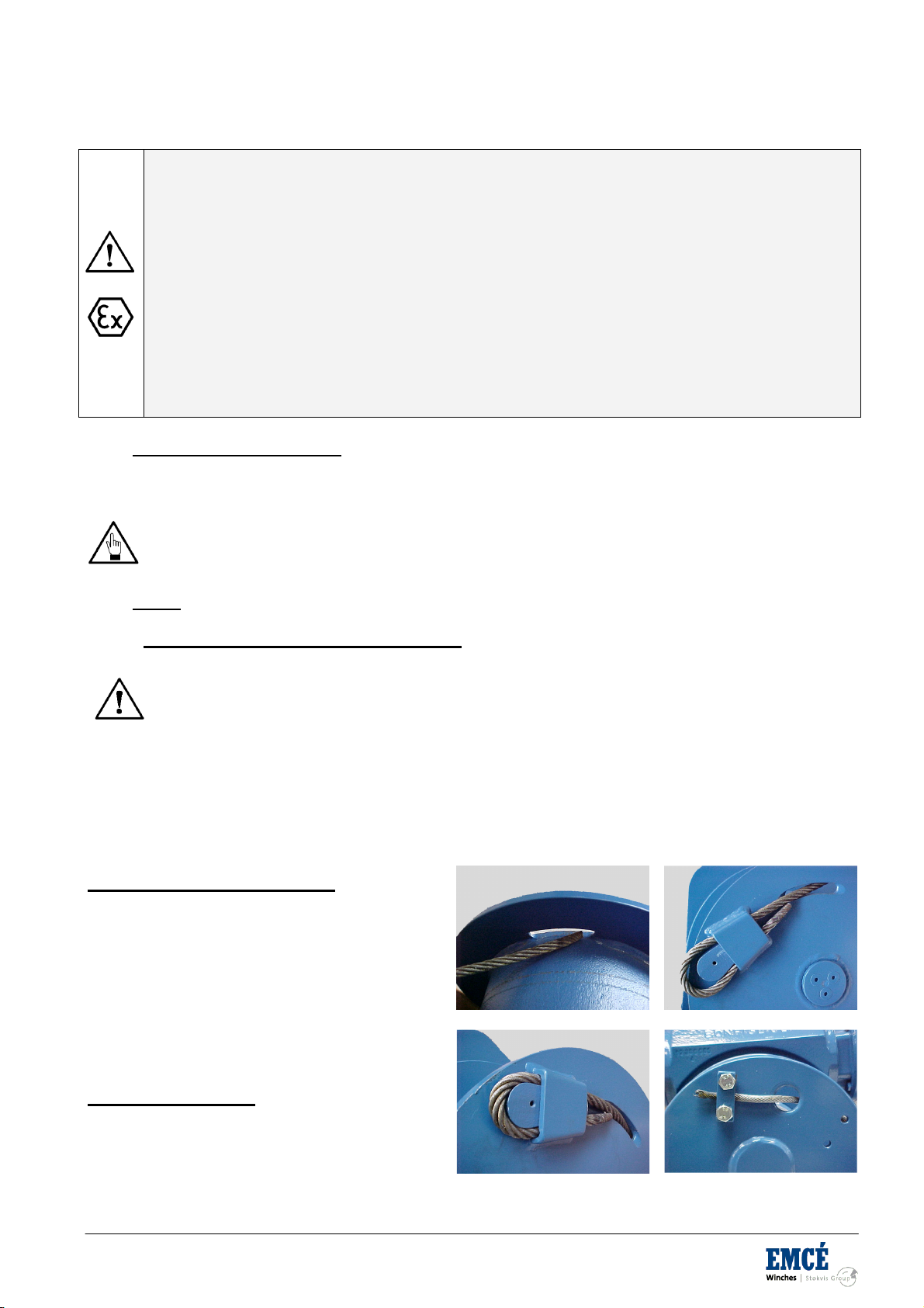
Fit wire dead end from the inside of the drum to the outside through the slotted hole in one of the drum flanges
(see picture 4.3.1)
Fastening with pocket and wedge
The wire dead end shall be fitted in the pocked as
to make an eye around the wire wedge with free
end fitted backwards through the pocket (see
picture 4.3.2).
Pull the wire from the opposite side to press wire
and wedge into the pocket (see picture 4.3.3). The
free end of the wire end shall at al times be 5
times the rope diameter and the rope end shall be
prevented from fraying.
Fitting with wire clamp
Fit the wire as shown on picture 1 and through the
wire clamp on the drum flange.
Tighten wire clamp bolts according to the table in
section 4.1(see picture 4.3.4).
Picture 4.3.1 Picture 4.3.2
Picture 4.3.3 Picture 4.3.4
General Manual Electric Winches with UMPH rope-English Rev.1.1 – 10-12-2014
Other possibilities
In some cases a different fastening of the rope than mentioned before is provided. In these cases the rope is
fastened by means of:
A hole in the drum with several fixing bolts
Special wire clamps on the drum
Always keep a minimum of 6 wire coils winded around the drum to warrant a safe winch load
holding. The wire dead end fastening alone is not sufficient to hold the winch load.
Make sure that wire clamp bolts don't pass over the flange plate. If it happens, shorten the
bolts to avoid rope damage.
Never fit a wire longer than the maximum allowed to avoid excess wire layers non conforming
to safety rules.
The first winding of the wire to the drum shall be such to obtain a perfect compactness of the
wire coils and leave no space between the coils. Keep the wire under tension during the first
winding operation. The wire can be easily damaged should it be wedged under load between
non compacted under laying coils.
4.3.2 Handling and installation of the rope
Handling and installation of the rope should be carried out in accordance with a detailed plan and should be
supervised by a competent person.
Incorrectly supervised handling and installation procedures may result in serious injury to
persons in the vicinity of the operation as well as those persons directly involved in the
handling and installation.
Wear suitable protective clothing such as overalls, industrial gloves, helmet, eye protectors and safety footwear
Failure to wear suitable protective clothing and equipment may result in skin problems from
over exposure to certain types of rope lubricants and dressing
Ensure that the correct rope has been supplied by checking to see that the description on the Certificate is in
accordance with that specified in the purchaser’s order.
Check by measurement that the nominal diameter of the new rope conforms to the nominal size stated on the
Certificate. Examine the rope visually to ensure that no damage or obvious signs of deterioration have taken
place during storage or transportation to the
installation site.
Check the working area around the equipment for any potential hazards which may affect the safe installation of
the rope.
Check the condition of the rope-related equipment in accordance with the OEM’s instructions. Include the
following:
Drum
Check the general condition of the drum.
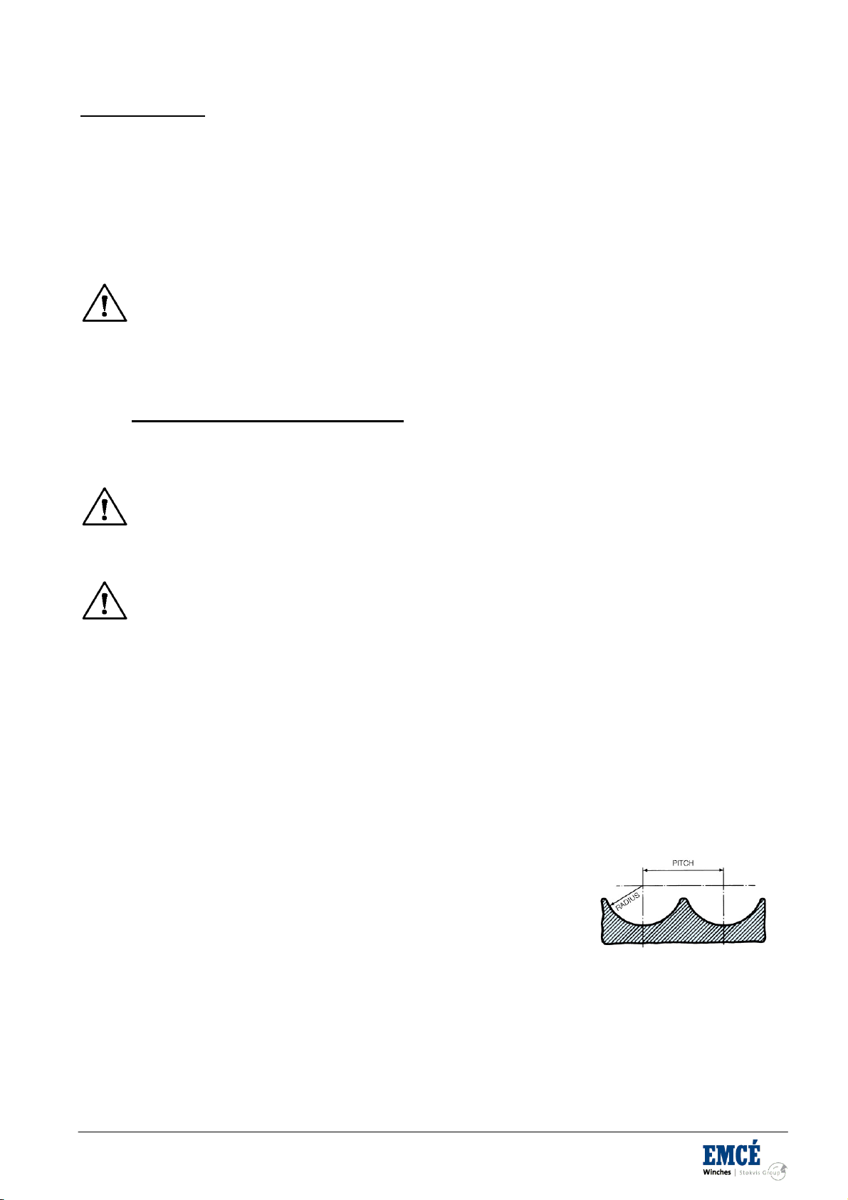
If the drum is grooved, check the radius and pitch and ensure that the
grooves will satisfactorily accommodate the size of the new rope (see
Fig 3)
Sheaves
Ensure that the grooving is of the correct shape and size for the new rope
Check that all sheaves are free to rotate and in good condition.
Rope Guards
Check that any rope guards are correctly fitted and are in good condition.
Check the condition of any wear plates or rollers which are protecting structural members.

General Manual Electric Winches with UMPH rope-English Rev.1.1 – 10-12-2014
Failure to carry out any of the above could result in unsatisfactory and unsafe rope
performance.
Coils
Place the coil on the ground and roll it out straight ensuring that it does
not become contaminated with dust/grit, moisture or any other harmful
material.
If the coil is too large to physically handle it may be placed on a ‘swift’
turntable and the outside end of the rope pulled out allowing the coil to
rotate.
Never pull a rope away from a stationary coil as
this will induce turn into the rope and kinks will
form. These will adversely affect rope
performance.
Reels
Pass a shaft through the reel and place the reel in a suitably anchored stand which allows it to rotate
and be braked to avoid overrun during installation. Where multi-layer coiling is involved it may be
necessary for the reel to be placed in equipment which has the capability of providing a back tension in
the rope as it is being transferred from reel to drum. This is to ensure that the underlying (and
subsequent) laps are wound tightly on the drum.
Position the reel and stand such that the fleet angle during
installation is limited to 1.5 degrees.
If a loop forms in the rope ensure that it does not tighten
to form a kink.
Ensure that the reel stand is mounted so as not to create a
reverse bend during reeving (i.e. for a winch drum with an overlap
rope, take the rope off the top of the reel).
Ensure that any equipment or machinery to be roped is correctly and safely positioned and isolated
from normal usage before installation commences. Refer to the OEM’s instruction manual and the
relevant ‘Code of Practice’.
When releasing the outboard end of the rope from a reel or coil, ensure that this is done in a controlled manner.
On release of the bindings and servings used for packaging, the rope will want to straighten itself from its
previously bent position. Unless controlled, this could be a violent action. Stand clear.
Failure to control could result in injury.
Ensure that the as-manufactured condition of the rope is maintained during installation.
If installing the new rope with the aid of an old one, one method is to fit a rope sock (or stocking) to each of the
rope ends. Always ensure that the open end of the sock (or stocking) is securely attached to the rope by a
serving or alternatively by a clip (See Fig. 9). Connect the two ends via a length of fibre rope of adequate
A kink can severely affect the strength of a six
strand rope and can result in distortion of a
rotation- resistant or low rotation rope leading
to its immediate discard.
General Manual Electric Winches with UMPH rope-English Rev.1.1 – 10-12-2014
strength in order to avoid turn being transmitted from the old rope into the new rope. Alternatively a length of
fibre or steel rope of adequate strength may be reeved into the system for use as a pilot/messenger line. Do not
use a swivel during the installation of the rope.
Monitor the rope carefully as it is being pulled into the system and make sure that it is not obstructed by any part
of the structure or mechanism which may cause the rope to come free.
Failure to monitor during this operation could result in injury.
This entire operation should be carried out carefully and slowly under the supervision of a competent person.
When coiling a rope on a plain (or smooth) barrel drum ensure that each lap lies tightly against the preceding
lap. The application of tension in the rope greatly assists in the coiling of the rope.
Any looseness or uneven winding will result in excessive wear, crushing and distortion of the
rope.
When multi layer coiling has to be used it should be realized that after the first layer is wound on a drum, the
rope has to cross the underlying rope in order to advance across the drum in the second layer. The
points at which the turns in the upper layer cross those of the lower layer are known as the cross-over points
and the rope in these areas is susceptible to increased abrasion and crushing. Care should be taken when
installing a rope on a drum and when operating a machine to ensure that the rope is coiled and layered
correctly.
Limit switches, if fitted, must be checked and re-adjusted, if necessary, after the rope has been installed.
Record the following details on the Certificate after installation has been completed: type of equipment, location,
plant reference number, duty and date of installation and any re-rating information/signature of competent
person. Then safely file the Certificate.
Run in’ the new rope by operating the equipment slowly, preferably with a low load, for several cycles. This
permits the new rope to adjust itself gradually to working conditions.
Unless otherwise required by a certifying authority, the rope should be in this condition before
any proof test of the equipment or machinery is carried out.
Check that the new rope is spooling correctly on the drum and that no slack or cross laps develop. Apply a back
tension in the order of 2% to 5% of the strength of the rope in order to achieve tight and even coiling especially
on the first layer..
Where multi-layer coiling is unavoidable, succeeding layers should coil evenly on the preceding layers of rope.
Irregular coiling usually results in severe surface wear and rope malformation, which in turn is
likely to cause premature rope failure.
Ensure that the as-manufactured condition of the rope is maintained throughout the whole of the handling and
installation operation.
4.4 START UP SEQUENCE
1. Check lubricating oil level and fill up if necessary;
2. Make a few trials without load before fitting the wire to check a correct operation of the system;
3. Fit the wire as described in section (4.3);
4. Make a few lifting trials with reduced load to check the correct operation of the brake and the limit
switches (optional), pay attention to excessive or unexplained noises;
5.
Check for correct working of the load limiting device (optional).

General Manual Electric Winches with UMPH rope-English Rev.1.1 – 10-12-2014
5. WORKING WITH THE MACHINE
5.1 START, NORMAL OPERATION AND STOP
5.1.1 Check list for prestart preparation
1. Perform the frequent inspection (see chapter 5.2) at the beginning of each shift.
2. Do not operate winch with any personnel near the line of force or capable of coming into contact with
moving parts.
3. Ease the slack out of the rope when starting a lift. Do not jerk the load.
4. Ensure that all personnel and spectators are clear of the load and winch;
5. Make sure that working conditions conform to winch features;
5.1.2 Operating instructions
The following descriptions cover the functional operation of the winch controls only. It does not cover any
operations performed using the winch. It is the operators responsibility to understand all facets of the operation.
The operator must be physically capable and mentally alert. They must have good hearing,
vision and depth perception. The operator must make sure all conditions are safe for operations. If the operator
feels that anything is unsafe, or even questionable, do not proceed until properly evaluated or corrected.
Standard our products are delivered without control. Below an operating instruction is given about the optional
controls EMCÉ can deliver. In case controls are obtained from another supplier please use the instruction
manual from the supplier for safe use.
On winches with an optional manual operated bandbrake, the bandbrake must first be
released before the below operation of the winch can be performed.
On winches with an optional manual operated clutch, the clutch must be engaged before the
below operation of the winch can be performed.
Before start up
Turn speed control potentiometer on main control panel in position “0” (only applicable for controls with
a frequency inverter).
“Paying in”
Press the “in” button on the main control panel. Check if the cable is spooling correct and if the load in
the winch wire is stable.
Turn the speed control potentiometer on main control panel up till the winch is slowly rotating. Before
increasing the speed of the winch check if the cable is spooling correct and if the load in the winch wire
is stable (only applicable for controls with a frequency inverter).
“Paying out””
Press the “out” button on the main control panel. Check if the cable is spooling correct and if the load in
the winch wire is stable.
Turn the speed control potentiometer on main control panel up till the winch is slowly rotating. Before
increasing the speed of the winch check if the cable is spooling correct and if the load in the winch wire
is stable (only applicable for controls with a frequency inverter).
For winches with frequency inverters that do not have motors with forced ventilation the
running times of the winch at slow speed are limited due to the reduced cooling capacity of the
motor at slow speeds. For such winches we recommend to use the winch mainly on slow
speed during starting, stopping and positioning.
To stop the winch
Turn speed control potentiometer on main control panel in position “0” (only applicable for controls with
a frequency inverter).
Release “in” or “out” button
Emergency stop (optional)
Turn the button for normal operation (button in upper position). To stop the winch push the button down. To
reset the emergency stop turn the button to the upper position.

General Manual Electric Winches with UMPH rope-English Rev.1.1 – 10-12-2014
Manual operated bandbrake (optional)
The bandbrake on a winch can be used to lock the winch drum
during maintenance or when the disengagement clutch on the
drum is released. When a load remains in the cable after the job
with the winch is finished the bandbrake should also be engaged
to prevent that the loads remains on the winch drive when the
winch is not in use. Before the winch is taken back into service the
bandbrake must first be released. Below the instructions for the
bandbrake operation are given.
Closing
Push the handle towards it’s outer limit in the direction of
the bandbrake rim (overcentre type bandbrake)
Rotate the handle (clockwise) up till the bandbrake is
firmly locked (wind-on type bandbrake)
Opening
Pull the handle towards you up till it’s outer limit
(overcentre type bandbrake)
Rotate the handle (counter clockwise) up till the
bandbrake is fully free of the brake rim (wind-on type
bandbrake)
Manual operated clutch (optional)
With a clutch the winch drum can be disengaged from the winch
drive, which allows to walk out the cable. Below the instructions
are given for the operation of the clutch.
Closing
Close the bandbrake (when available)
Turn the drum shaft up till the pins/claws of the clutch are
placed before the corresponding openings on the winch
drum. Depending on the type of winch the shaft can be
rotated as follows
oWith a hand wheel on the winch drive
oBy operating the winch at a slow speed
When the above methods are not possible the last option
is to rotate the drum manually up till it is in the correct
position compared to the pins/claws of the clutch.
Move the handle in the direction of the winch drum up till
the clutch is fully closed.
Open the bandbrake before the winch is used (when
available).
Opening
Close the bandbrake (when available)
Turn the drum shaft up till the pins/claws of the clutch are
not making contact anymore with the corresponding
openings on the winch drum. Depending on the type of
winch the shaft can be rotated as follows
oWith a hand wheel on the winch drive
oBy operating the winch at a slow speed
When the above methods are not possible the last option
is to rotate the drum manually up till it is in the correct
position compared to the pins/claws of the clutch.
Move the handle in the drum support bearing up till the
clutch is fully free of the winch drum.
Open the bandbrake before the winch is used (when
available).
Overcentre type bandbrake
Wind-on bandbrake
Manual operated clutch

General Manual Electric Winches with UMPH rope-English Rev.1.1 – 10-12-2014
On a winch without bandbrake the clutch may only be operated when there is no load in the
cable.
The winch drum may only be rotated manually when there is no load in the cable.
Before rotating the winch drum manually, the winch must be isolated from the main supply. A
dangerous occurrence is likely to occur if the motor is powered.
Emergency hand crank (optional)
Before engaging the emergency hand crank, the winch must be isolated from the main
electrical, hydraulic or air supply. A dangerous occurrence is likely to occur if the motor is
powered with the crank handle engaged.
The crank handle is connected to the winch frame by mean of a wing nut. Remove the handle from
the winch frame.
Depending on the winch type the hand crank should be fitted as follows
oOn the gearbox input shaft opposite to the motor is a recessed shaft protected by a nylon
plug. Remove the plug and slot the crank handle onto the keyway.
oOn the back of the motor is a recessed shaft protected by a nylon plug. Remove the plug
and slot the crank handle onto the keyway.
Ascertain the direction of rotation by turning the crank handle two or three revolutions.
Thereafter, continue to wind in the direction required to recover the load or person suspended from
the winch rope.
In case the winch is supplied with one or more brakes, carefully release the brakes before us
e of the emergency hand crank. To make sure that the load not drops when releasing the
brakes, the emergency crank must be locked during release of the brakes or hold tight by an
operator.
In case a self braking hand crank is fitted the opening on the side of the crank should be
placed over the locking pin.
In case the winch is equipped with a self braking worm gearbox (reduction of 80 to 100) the
load will be sustained by the gearbox even when the brakes are released.
5.2 INSPECTIONS
Before use, free the unit from snow, ice, sand, gravel or other interfering matter.
All new, altered or modified equipment should be inspected and tested by personnel instructed
in safety, operation and maintenance of this equipment to ensure safe operation at rated
specifications before placing equipment in service.
Never use a winch when inspection indicates is damaged. Frequent and periodic inspections
should be performed on equipment in regular service.
Observe the routine inspection and maintenance schedule to ensure suitable operating
conditions and the effective explosion protection of the unit.
Frequent inspections are visual examinations performed by operators or service personnel during routine winch
operation. Periodic inspections are thorough inspections performed by personnel trained in inspection of the
winch. Inspection intervals depend upon the nature of the critical components of the equipment and the severity
of usage. Careful inspection on a regular basis will reveal potentially dangerous conditions while still in the early
stages, allowing corrective action to be taken before the condition becomes dangerous. Deficiencies revealed
through inspection, or noted during operation, must be reported to an appointed person. A determination must
be made as to whether a deficiency constitutes a safety hazard before resuming operation of the winch.
Records and Reports
Some form of inspection record must be maintained for each winch, listing all points requiring periodic
inspection. A written report should be made monthly on the condition of the critical parts of each winch. These

General Manual Electric Winches with UMPH rope-English Rev.1.1 – 10-12-2014
reports should be dated, signed by the person who performed the inspection, and kept on file where they are
readily available for review.
Rope Reports
Records should be maintained as part of a long-range rope inspection program. Records should include the
condition of rope removed from service. Accurate records will establish a relation ship between visual
observations noted during frequent inspections and the actual condition of rope as determined by periodic
inspections.
Frequent Inspection
On equipment in continuous service, frequent inspection should be made by operators at the beginning of each
shift. In addition, visual inspections should be conducted during regular operation for indication of damage or
evidence of malfunction (such as abnormal noises).
1. WINCH. Prior to operation, visually inspect winch housings, controls, brakes and drum for indications of
damage. Do not operate the winch unless the rope feeds into the drum smoothly. Any discrepancies
noted must be reviewed and inspected further by authorized personnel instructed in the operation,
safety and maintenance of this winch.
2. FIBER ROPE. Visually inspect all rope which can be expected to be in use during the day's operations.
Inspect for wear and damage indicated by distortion of rope such as kicking, "birdcaging", core
protrusion, main strand displacement, corrosion, broken or cut strands. If damage is evident, do not
operate winch until the discrepancies have been reviewed and inspected further by personnel
instructed in the operation, safety and maintenance of this winch.
The full extent of rope wear cannot be determined by visual inspection. At any indication of
wear inspect the rope in accordance with instructions in "Periodic Inspection."
3. ELECTRIC SYSTEM: Check connections of power supply. Electric wiring connections, if in doubt check
phase cycle, voltage dip during operation and current supply. (Fix loose wiring or exposed wiring or
connections).
4. CONTROLS. During operation of winch, verify response to control is quick and smooth. If winch
responds slowly or movement is unsatisfactory, do not operate winch until all problems have been
corrected.
5. BRAKES. During winch operation test brakes. Brakes must hold load without slipping. Automatic brakes
must release when winch motor throttle is operated. If brakes do not hold load, or do not release
properly, the brakes must be adjusted or repaired.
6. ROPE REEVING. Check reeving and ensure rope is properly secured to the drum.
7. LUBRICATION. Refer to section 7 for recommended procedures and lubricants.
Periodic Inspection
Frequency of periodic inspection primarily depends on the severity of usage :
NORMAL : semi-annually
HEAVY : quarterly
SEVERE : monthly
Keep accumulative written records of periodic inspections to provide a basis for continuing evaluation. Inspect
all items listed in "Frequent Inspection". Also inspect the following :
1. FRAME and UPRIGHT. Check for deformed, or cracked or corroded main components. If external
evidence indicates the need for additional inspection return winch to your nearest EMCÉ service repair
center.
2. FASTENERS. Check retainer rings , split pins, cap screws, nuts, and other fasteners on winch,
including mounting bolts. Replace if missing or damaged and tighten if loose.
3. DRUM AND SHEAVES. Check for cracks, wear or damage. Replace if necessary.
4. FIBER ROPE. In addition to Frequent Inspection requirements, also inspect for the following:
a. Build-up of dirt. Remove dirt and corrosion if necessary.
b. Loose or damaged end connection. Replace if loose or damaged
c. Check whether the fiber rope is secured properly to the drum.
d. Verify fiber rope diameter. Measure the diameter of the fiber rope from crown-to-crown
throughout the life of the rope. Recording of the actual diameter should only be done with the
fiber rope under equivalent loading and in the same operating section as accomplished during
This manual suits for next models
1
Table of contents
Popular Winch manuals by other brands


Sherpa
Sherpa 4x4 Stallion owner's manual

RIDGE RYDER
RIDGE RYDER 341685 instructions

Ronstan
Ronstan ORBITBLOCKS User instructions

PREMIER WINCH
PREMIER WINCH DV-6000S manual

HADEF
HADEF 46/21E Installation, Operating and Maintenance Instruction

Ramsey Winch
Ramsey Winch 600 Series Operating, Service and Maintenance Manual


