PREMIER WINCH DV-6000S User manual

1
Self-Recovery Winch
Thank you for purchasing a PREMIER WINCH. This manual covers operation and
maintenance of the winch. All information in this publication is based on the latest
production information available at the time of printing.
General Safety Precautions
Every PREMIER WINCH is designed to give safe and dependable service if operated
according to the instructions. Read and understand this manual before installation and
operation of winch.
Follow these general safety precautions:
˙Confirm that the winch is suitable for the operation and conditions
˙Ensure that the winch is securely mounted and the rope wound correctly.
˙Don't use unsuitable pulleys or accessories.
˙Genuine replacement parts should only be used.
˙Check the winch for smooth operation without load prior to any recovery.
˙Make sure the wire rope is wound evenly on the first layer on the drum, rewind it if not.
1. The winch is designed as a vehicle self-recovery unit and only rated for
intermittent-periodic duty.
2. The winch is not to be used to lift, support or otherwise transport personnel.
3. A minimum of five (5) wraps of rope must remain on the drum at all times to support
the rated load.
4. When choosing a winch, you need to consider the vehicles size and weight. As a
general guide, you will need a winch with a maximum load rating of at least one to
one and a half times greater than the gross vehicle weight.
5. The rated line pull of the winch must be powerful enough to overcome the added
resistance caused by whatever the vehicle is stuck in.
WARNING
2
Fleet angle
Centre line of anchor
point
I.Safety Precautions
This winch is designed to give safe, dependable service and trouble-free operation. Please read and
understand this Instruction Manual before installing and operating your winch.
Precautions before use:
Confirm that the winch is suitable for the application before use.
Because the maximum load capacity decreases corresponding to the increase in the number of
layers, wind the rope according to the instructions in this manual.
Mount the winch securely and ensure that the rope is attached correctly.
Genuine replacement parts should only be used.
If a hook or pulley blocks are to be used, ensure that they are correct for the application, and
remember that a pulley block should be rated at least twice the capacity of the winch.
Precautions at the time of operation of the winch are listed as follows:
The operator of a winch in some cases, is required to hold qualifications
according to applicable laws and ordinances.
Only a responsible person should operate the winch.
Prior to use, carry out the daily checks without fail, and use only
after confirming the winch is functioning correctly.
Aminimum of 5 wraps of rope must remain on the drum at all times!
Do not use winch to move people
Keep hands clear of wire rope and fairlead opening.
Use leather gloves or a heavy rag when handling the wire rope.
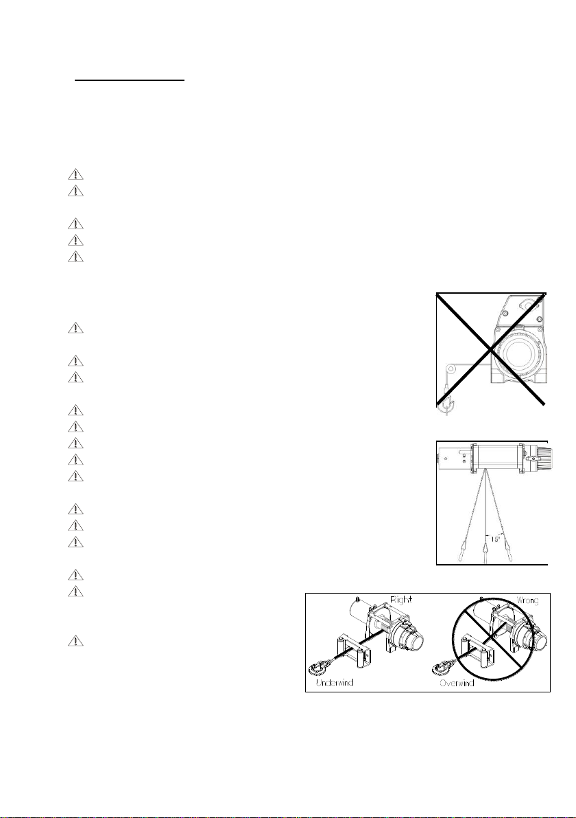
The winch is not to be used as a lifting device or a hoist for vertical lifting
(Fig1)
Do not exceed maximum line pull ratings shown in these instructions.
Do not impose shock loads on the winch.
Pull from an angle below 15 degree when straightening up the vehicle or
load. (Fig 2)
Run the engine during winching operations to keep battery charged.
When winching a heavy load, lay a heavy
blanket or jacket over the wire Rope, near to
the hook end.
Always operate your winch in an
underwound orientation only. (Fig3)
(Fig 1)
(Fig2)
(Fig3)

3
II.Performance Data
Specifications
Model
DV-6000S
DV-9000ES
DV-9000i
DV-12 light
DV-12000ES
DV-15000ES
Line Pull (first layer)
2,722kg / 6,000lb
4,082kg / 9,000lb
5,443kg/12,000lb
5,443kg/12,000lb
6,803kg/15,000lb
Line Speed (first layer, no load)
8.0mpm / 26.2fpm
13.4mpm / 44fpm
8.0mpm / 26.2fpm
8.3mpm/27fpm
6.9mpm/22fpm
Line Speed (first layer, full load)
2.0mpm / 6.5fpm
2.0mpm / 6.4fpm
1.0mpm / 3.3fpm
1.2mpm/4.0fpm
0.8mpm/2.5fpm
Amp. Draw
no load 12V
60A
55A
50A
60A
60A
full load 12V
300A
350A
350A
440A
460A
no load 24V
35A
30A
30A
50A
50A
full load 24V
200A
210A
210A
290A
340A
Motor
Type
Series wound
Output
12V
2,390w / 3.2hp
3,430w / 4.6hp
3,430w / 4.6hp
4,175w/5.6hp
24V
1,490w / 2.0hp
1,940w / 2.6hp
1,940w / 2.6hp
2,684w/3.6hp
Gear Train
Type
3 stage planetary
Ratio
216:1
156:1
211:1
261:1
315:1
Clutch
Rotating ring-gear
Brake
Automatic, full load CBS (Cone Brake Structure)
Control
Detachable control
box
Detachable
control box
Bridge
control box
Detachable control
box
Detachable control box
Wire Rope
Type
Galvanized aircraft A7 x 19
6 x 29-IWRC
Length
24.4m / 80ft
30.5m / 100ft
25m / 82ft
38m / 125ft
27m / 89ft
Size
7mm / 9/32”
8mm / 21/64”
9.5mm / 3/8”
9.5mm / 3/8”
11mm / 7/16”
Performance
Layer
Model
DV-6000S
DV-9000ES
DV-9000i
DV-12 light
DV-12000ES
DV-15000ES
1st
Layer
Line Pull
kg / lb
2,722 / 6,000
4,082 / 9,000
4,082 / 9,000
5,443 /
12,000
5,443 /
12,000
6,804 /
15,000
Total Rope on
the Drum m/ft
3.8 / 12.5
6.1 / 20.0
6.1 / 20.0
5.4 / 17.7
6.6 /21.5
5.7 / 18.6
2nd
Layer
Line Pull
kg / lb
2,266 / 4,995
3,316 / 7,310
3,316 / 7,310
4,319 /
9,522
4,563 /
10,060
5,569 /
12,277
Total Rope on
the Drum m/ft
8.4 / 27.5
13.6 / 44.7
13.6 / 44.7
12.2 / 40.0
14.4 / 47.2
12.6 / 41.4
3rd
Layer
Line Pull
kg / lb
1,941 / 4,279
2,792 / 6,154
2,792 / 6,154
3,580 /
7,893
3,928 / 8,659
4,713 /
10,391
Total Rope on
the Drum m/ft
13.7 / 45.0
22.6 / 74.0
22.6 / 74.0
20.5 / 67.3
23.5 / 77.0
20.8 / 68.3
4th
Layer
Line Pull
kg / lb
1,697 / 3,742
2,410 / 5,314
2,410 / 5,314
3,056 /
6,737
3,448 / 7,601
4,086 / 9,007
Total Rope on
the Drum m/ft
19.8 / 65.1
30.5 /100
30.5 /100
25.0 / 82.0
33.8 / 110.9
27.1 / 89
5th
Layer
Line Pull
kg / lb
1,508 / 3,325
3,072 / 6,774
Total Rope on
the Drum m/ft
24.4 / 80
38.1 / 125

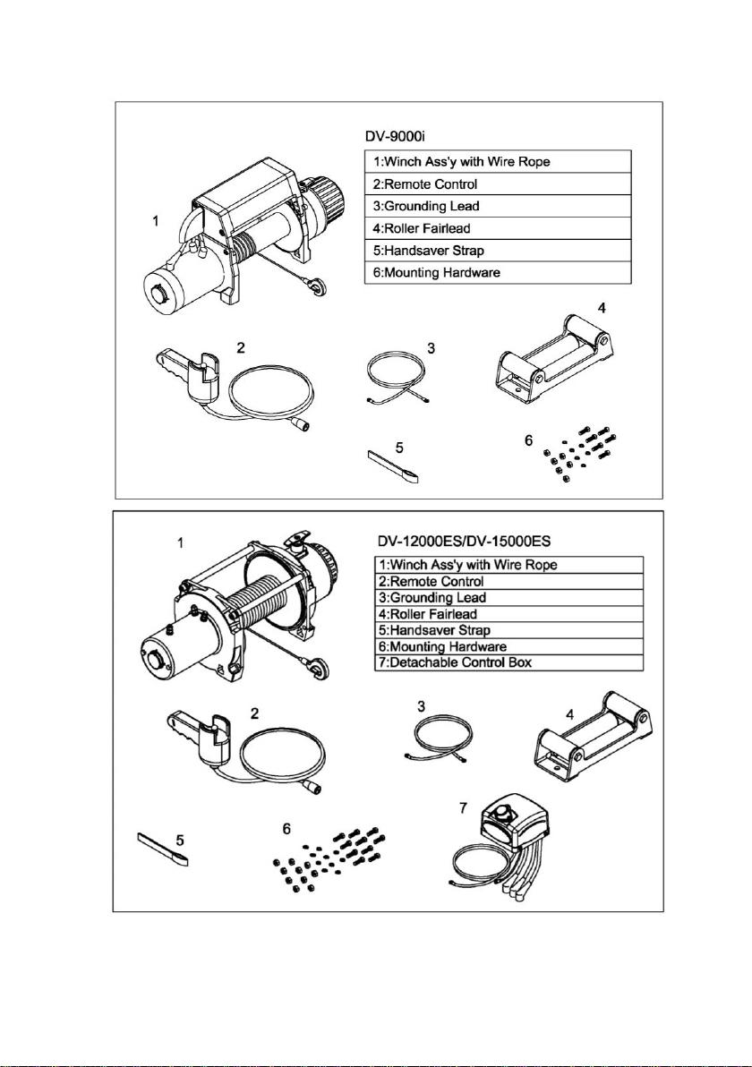
4
Main Components
5
This manual suits for next models
5
Table of contents
Popular Winch manuals by other brands


Comeup
Comeup DV-9 manual

Orvea
Orvea Italwinch 805 Installation and user manual

Prowinch
Prowinch PWJTHF300 user manual

Clas Ohlson
Clas Ohlson LD2000-A manual

Runva
Runva EWD8000 Assembly & operating instructions

Ingersoll-Rand
Ingersoll-Rand LIFTSTAR FG 1500/CN Series Parts, operation and maintenance manual