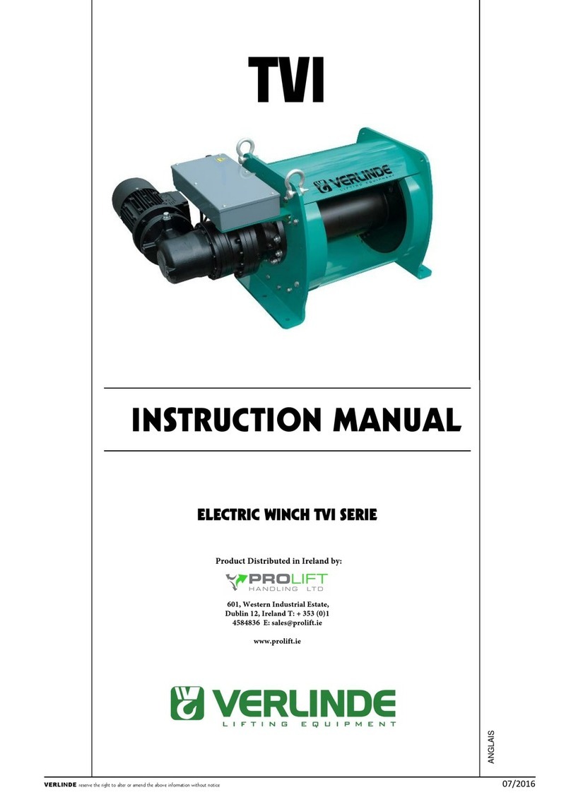
Verlinde TIRLIFT 2 User manual

VERLINDE reserves the right to alter or amend the above information without notice
11/2018
Owner’s Manual
Electric winches
250 to 1500 kg
English

OWNER’S MANUAL
2
VERLINDE reserves the right to alter or amend the above information without notice
11/2018
Contents
1. Conditions of use ............................................................................................................... p. 3
2. Safety instructions .............................................................................................................. p. 4
3. Warranty ............................................................................................................................ p. 5
4. Reception of the equipment ............................................................................................... p. 5
5. Obligatory regulatory checks by the user ........................................................................... p. 6
6. Presentation of the machines ............................................................................................. p. 7
6.1 Technical description
6.2 Operation
6.3 Available models
6.4 Dimensions and fastenings
6.5 Accessories
6.6 FEM classification
6.7 Variable speed drive
7. Handling – Storage ............................................................................................................ p. 14
8. Assembly and start-up ....................................................................................................... p. 14
8.1 Securing the winch
8.2 Wire rope exits
8.3 Change to initial assembly
8.4 Set-up
8.5 Electrical connections
9. Servicing and maintenance ................................................................................................ p. 26
9.1 Winches
9.2 Ropes
9.3 Hooks
9.4 Brake
10. Taking out of use ............................................................................................................... p. 28
11. Spare parts ........................................................................................................................ p. 29
12. Operating faults.................................................................................................................. p. 30
13. Tests .................................................................................................................................. p. 31
14. Declaration of EC conformity.............................................................................................. p. 31
15. Appendices ........................................................................................................................ p. 33

OWNER’S MANUAL
3
VERLINDE reserves the right to alter or amend the above information without notice
11/2018
1 - Conditions of use
All users must read the set-up instructions carefully before using the product for the first time. These
instructions should enable the user to familiarise themselves with the winch and use it to its full
capacity. The set-up instructions contain important information about how to use the winch safely and
correctly. Compliance with these instructions helps to avoid danger, reduce repair costs, reduce
stoppage time and improve the reliability and service life of the winch. The instruction manual must
always be available in the place where the winch is being used. In addition to the set-up instructions
and regulations concerning the prevention of accidents, the work safety and professional regulations
in force in each country must also be respected.
This equipment is governed by European regulations and more specifically Directive 2006/42/EC on
machinery, EMC Directive 2004/108/EC and LVD 2006/95/EC, as well as the EN 14492/1 standard.
These winches are designed to move loads using a suitable steel rope. They have been designed to
perform lifting and pulling operations within the defined load capacity limit and with safety factor 5
(static against sudden failure).
For use in lifting, the European regulation makes certain equipment obligatory, such as a limit
switch system and, for loads of 1,000 kg or more, a load limiter.
The operator must check the presence of this equipment (available as an option from the
manufacturer) before using the product for lifting purposes.
The capacity indicated on the winch corresponds to the maximum capacity of use (MCU); in no
event should this capacity be exceeded.
THIS WINCH CAN UNDER NO CIRCUMSTANCES BE USED TO LIFT PEOPLE.
Do not begin moving the load until you have attached it correctly and checked that all personnel
are outside the danger zone.
Before use, the operator must always check that the machine, rope, hook, markings and moorings
are in good working order.
The operator must check that the load is attached in such a way that the winch, the rope and the
load place neither the operator nor any other person is in danger.
The winches can be used at ambient temperatures ranging from -10°C to +50°C. Please consult
the manufacturer in the event of extreme conditions of use.
Important: In the event of an ambient temperature below 0°C, the brake must be tested to ensure that
there are no operating faults resulting from the freezing conditions.
The data concerning the heat-resistance of the steel rope and its fastenings must be available on
request from the manufacturer and must be respected.
VERLINDE cannot accept any liability for the consequences resulting from the use or installation of
equipment not provided for in the present instructions or for the consequences of removal,
modification or replacement of original parts or components with parts or components from other
sources without the written agreement of VERLINDE.
The use of winches requires strict compliance with the accident prevention and safety measures in
force in the country where they are used.
YOU MUST ALSO RESPECT THE REGULATIONS APPLICABLE IN YOUR COUNTRY.

OWNER’S MANUAL
4
VERLINDE reserves the right to alter or amend the above information without notice
11/2018
2 - Safety instructions
Before using the equipment, check that there are no causes of overloading such as: adhesion to the
ground, suction, jamming, etc. of the load.
As the operator of the winch, you are responsible for your own safety and the safety of your
colleagues in the work zone of the machine.
The operator must respect all the following safety information, without exception, concerning the
handling and operation of the winch as well as the references to other sections of this instruction
manual. Failure to comply with these instructions increases the level of risk.
Only the people designated by the company are authorised to operate the winch
Before using the winch for the first time, familiarise yourself with its conditions of use. To this end,
read the present instruction manual carefully and in its entirety and perform all the operations
described herein one after the other.
Inform your departmental manager or the safety officer of any malfunction so that the fault can be
repaired immediately.
Respect the directives of the industrial accident prevention organisations such as, in France, the
Caisse Régionale d’Assurance Retraite et de la Santé au Travail (C.A.R.S.A.T.) and the Health
and Safety Committee (HSC) of your company, if one exists.
Scrupulously respect all information in the sections concerning the CONDITIONS OF USE
(section §1) and the WORK ROPE (section §8.5.4).
The operator(s) must have an unimpeded view of the load.
Please ensure that the operator is qualified to operate the machine in the conditions provided for
in this manual. This will ensure the safety of both people and the environment.
Do not lift or transport loads when there are personnel inside the danger zone.
Do not authorise the personnel to walk under a suspended load.
Do not leave a load suspended or with the rope taut unsupervised.
In addition to the above instructions, we must warn you against all incorrect use or handling listed
below. It is dangerous and prohibited to:
unwind the drum completely (keep 2 to 3 residual windings).
pull at an angle.
swing the load.
use ropes of a different diameter and texture to those specified in this instruction manual
(FEM 1 Am – ISO M4 for 250 and 600 kg, FEM 1 Bm – ISO M3 for 350, 500, 800, 990 and 1500
kg).
use damaged ropes or ropes with splices.
grab or touch a moving rope or a rotating drum.
use hooks without a latch, which do not correspond to the loads indicated on the winch or
which are in poor condition.
insert objects into moving parts.
work on loaded winches or when the rope is taut.
use the winch rope as a towing chain.
drum on the control box (overheating of the motor and electrical equipment).
Place hands or clothes, etc. in contact with moving parts, in particular the areas where the
rope is wound in/out.

OWNER’S MANUAL
5
VERLINDE reserves the right to alter or amend the above information without notice
11/2018
3 - Warranty
Our electric winches are guaranteed for 2 years from the date of shipment (ex-works).
The seller undertakes to repair any operating fault resulting from a fault in the design, execution,
components or materials themselves.
The warranty does not cover wear and tear or damage resulting from a lack of regular or periodic
maintenance. It does not cover damage resulting from a lack of supervision, incorrect handling or an
incorrect use of the machines, in particular overloading, pulling at an angle, under or overvoltage or
incorrect connection.
The warranty does not apply to any disassembly, modification or replacement of mechanical or
electrical parts undertaken without our agreement or by a non-approved operator. The warranty only
applies to the manufacturer's original spare parts. During the warranty period, the seller must replace
or repair any parts recognised as faulty after inspection by the qualified and approved department, all
free of charge.
The warranty excludes all other services or compensation.
Repairs undertaken within the scope of the warranty are, in principle, performed in the seller's
workshops or the workshop of a representative approved by the manufacturer. When work is carried
out on the equipment outside of their workshops, the seller must cover the labour costs related to the
disassembly or reassembly of these parts if these operations are performed exclusively by their
personnel or a representative approved by the manufacturer. The parts replaced become the
property of the seller and must be returned to them at their own expense.
In the case of components with a particular relative importance not manufactured by the seller
themselves and which bear the brand of a specialist manufacturer, the warranty, which may vary
according to the manufacturer, is the same as that agreed by this manufacturer.
4 - Reception of the equipment
Make a visual inspection of the packaging to ensure that it is in good condition.
In the event of a problem, issue the usual reserves.
Check that the winch corresponds to your order.

OWNER’S MANUAL
6
VERLINDE reserves the right to alter or amend the above information without notice
11/2018
5 - Obligatory regulatory checks by the user
The users are required to comply with the standards in force in their country.
With regard to France:
Order of 1st March 2004 relating to the verification of lifting machines and accessories:
The modifications to the regulation relating to the use and verification of lifting machines and
accessories, which came into effect on 1st April 2005, impose new obligations on all users:
The suitability inspection that involves checking that the lifting machine is suitable for the work that
the user intends to carry out, as well as for the risks to which workers are exposed, and that the
intended operations are compatible with the conditions of use for the machine defined by the
manufacturer.
The assembly and installation inspection that involves ensuring that the lifting machine is
assembled and installed safely in accordance with the manufacturer's instruction manual,
The general periodic visits that involve an inspection of the state of preservation and the operating
tests.
The commissioning or recommissioning inspections in the event of a change in the place of use,
the configuration or the conditions of use on the same site; following the disassembly and
subsequent reassembly of the lifting machine; after any major replacement, repair or
transformation concerning the essential components of the lifting machine; or following any
accident caused by the failure of an essential component of the lifting machine.
The maintenance booklet (order of 2nd March 2004 applicable from 1st April 2005) which must be
used to record the maintenance operations carried out in accordance with the recommendations
of the manufacturer of the machine as well as any other inspection, maintenance operation, repair,
replacement or modification carried out on the machine. For each operation, it is essential to
record the date of the work, the names of the people and, where appropriate, the companies
which carried out the work, the nature of the operation and, if it is a periodic operation, the
frequency. If the operations involve the replacement of certain components of the machine, the
references of these components are indicated.
The inspections must be carried out in accordance with a protocol and are intended to ensure
preventive maintenance aimed at detecting any damage or defect liable to cause a hazard.

OWNER’S MANUAL
7
VERLINDE reserves the right to alter or amend the above information without notice
11/2018
6 - Presentation of the machines
TIRLIFT 2 winches are lifting and pulling machines manufactured according to the standards and
regulations in force.
6.1 Technical description
All versions
Rigid steel and cast aluminium structure.
Mechanically welded steel drum with wide flanges for safe and rational fastening of the
rope.
Single or three phase asynchronous motors.
Watertight reducer in oil bath with helical gears.
Single or three-phase standard power socket.
Emergency stop as standard.
Optional: integrated end limit switch.
Low Voltage versions only:
24 V or 190 V direct control electromagnetic brake.
Electrical equipment under watertight cover.
Very low voltage, 24 V remote control with socket – IP 65.
220/380 V three-phase control – IP 55 double insulation.
Speed variation versions only:
190 V direct control electromagnetic brake.
Electrical equipment under watertight cover.
Very low voltage, 24 V remote control – IP 65.
6.2 Operation:
The load and winding speed of the rope on the drum are obtained by reducing the rotation movement
of the electric motor via a shaft mounted helical gear unit.
Outside the motor's operating phases, a mechanical automatic brake stops and keeps the load in
position.
The brake for the speed variation and Low Voltage versions is independent and is electrically
controlled.
In Low Voltage version, the motor is controlled on and off using a three-button wired remote control
(up/down/emergency stop).
In the speed variation version, the motor rotation speed is adjusted using a potentiometer on the
remote control. The acceleration and deceleration phases are managed by the machine to prevent
sudden starts and stops (and progressive).

OWNER’S MANUAL
8
VERLINDE reserves the right to alter or amend the above information without notice
11/2018
6.3 Available models

OWNER’S MANUAL
9
VERLINDE reserves the right to alter or amend the above information without notice
11/2018

OWNER’S MANUAL
10
VERLINDE reserves the right to alter or amend the above information without notice
11/2018
6.4 Dimensions and fastenings
TIRLIFT 2 Low Voltage version
Models
TIRLIFT 2 250-500
TIRLIFT 2 600-1500
Standard Long Standard Long
A mm
According to motors, see table.
B mm
243
243
304
304
C mm
79
79
107,5
107,5
Ø D mm
121
121
159
159
E mm
255
255
318
463
Ø F mm
10,5
10,5
12,5
12,5
G mm
197
197
246
246
H mm
According to motors, see table.
I mm
68
68
62
62
J mm
23
23
29
29
K mm
356
471
495,5
495,5
L mm
According to motors, see table.
M mm
121,5
121,5
152
152
N mm
121,5
121,5
152
152
T mm
230
345
290
435
TIRLIFT 2 250-500
Standard Long
Motor kW A mm L (without/with
limit switch) mm
H mm A mm L (without/with limit
switch) mm
H mm
0,75
451
356/421
284,5
451
468/533
284,5
1,1
462
356/421
284,5
462
468/533
284,5
2,2
473
487,5/487,5
306,5
473
468/533
306,5
TIRLIFT 2 600-1500
Standard Long
Motor kW A mm L (without/with
limit switch) mm
H mm A mm L (without/with limit
switch) mm
H mm
0,75
535,5
456/516
332,5
535,5
601/661
332,5
1,1
543
456/516
332,5
543
601/661
332,5
1,5
541
456/516
332,5
541
601/661
332,5
2,2
554
507/516
332,5
554
601/661
332,5
3
558
511/516
332,5
558
601/661
332,5
4
558
533/533
332,5
558
601/661
332,5

OWNER’S MANUAL
11
VERLINDE reserves the right to alter or amend the above information without notice
11/2018
TIRLIFT 2 speed variation version
Models
TIRLIFT 2 250-500
TIRLIFT 2 600-1500
Standard Long Standard Long
A mm
According to motors, see table.
B mm
243
243
304
304
C mm
79
79
107,5
107,5
Ø D mm
121
121
159
159
E mm
255
370
318
463
Ø F mm
10,5
10,5
12,5
12,5
G mm
197
197
246
246
H mm
According to motors, see table.
I mm
68
68
62
62
J mm
23
23
29
29
K mm
356
471
495,5
495,5
L mm
According to motors, see table.
M mm
121,5
121,5
152
152
N mm
121,5
121,5
152
152
T mm
230
345
290
435
TIRLIFT 2 250-500
Standard Long
Motor kW A mm L (without/with
limit switch) mm
H mm A mm L (without/with limit
switch) mm
H mm
0,75
475
356/421
345
475
468/533
345
1,1
475
356/421
345
475
468/533
345
2,2
475
488/487,5
345
475
468/533
345
3,3
477
488/488
345
475
468/533
345
TIRLIFT 2 600-1500
Standard Long
Motor kW A mm L (without/with
limit switch) mm
H mm A mm L (without/with limit
switch) mm
H mm
0,75
574
456/516
391
574
601/661
391
1,1
574
456/516
391
574
601/661
391
1,5
574
456/516
391
574
601/661
391
2,2
574
495,5/516
391
574
601/661
391
3
574
511/516
391
574
601/661
391
4
574
533/533
449
574
601/661
449

OWNER’S MANUAL
12
VERLINDE reserves the right to alter or amend the above information without notice
11/2018
6.5 Accessories
TIRLIFT 2 winches can be delivered with ropes and accessories.
6.6 FEM classification
There are eight groups of mechanisms:
FEM 1 Dm 1 Cm 1 Bm 1 Am 2m 3m 4m 5m
ISO
M 1
M 2
M 3
M 4
M 5
M 6
M 7
M 8
To define the group for a lifting machine, winch or hoist, three essential parameters must be
considered:
a- The maximum load to be lifted
Including the weight of the rope and any lifting accessories present (hook etc.), except if they have a
total weight less than or equal to 5% of the load to be lifted.
b- The duty factor
Indicates the extent to which the lifting machine is used at maximum load or with a reduced load.
There are four different duty factors:
Light Lifting machines rarely subject to maximum load
and regularly used for very light loads. k ≤ 0.5
Medium Lifting machines quite often subject to maximum
load and regularly used for light loads. 0.5 < k ≤ 0.63
Heavy Lifting machines often subject to maximum load and
regularly used for medium loads. 0.63 < k ≤ 0.8
Very
heavy
Lifting machines regularly subject to loads close to
the maximum load. 0.8 < k ≤ 1
For an exact classification, it is preferable to calculate the average cubic value using the following
formula:
where:
ß = payload or partial load
rated capacity
t = operating time with payload or partial load + dead load
total operating time
Y =dead load
maximum capacity
t Δ= operating time with dead load only
total operating time

OWNER’S MANUAL
13
VERLINDE reserves the right to alter or amend the above information without notice
11/2018
c- Operating class
This is the operating time per day, on the basis of 250 working days per year.
The lifting machine is considered to be in operation when it is moving; however, it is not considered to be in
operation during downtimes, for example, between lifting and lowering.
These three parameters give the FEM classification for the TIRLIFT 2 :
TIRLIFT 2
Usage rate
Average operating time per day in hours.
30’
1 h
2 h
Light 1 Dm 1 Cm 1 Bm
Medium 1 Cm 1 Bm 1 Am
Heavy 1 Bm 1 Am 2m
Very heavy 1 Am 2m 3m
6.7. Variable speed drive
6.7.1. General
WARNING
The electronic speed control equipement of the electric motors are connected to potentially
dangerous voltages. When connecting, performing servicing or dismantling these appliances,
the greatest of precautions must be taken to prevent electric discharges.
This appliance contains capacitors which accumulate energy. When the appliance is switched
off, these capacitors retain a dangerous voltage for a few minutes subsequent to switching off.
Wait at least 5 minutes before opening or touching live parts of the appliance.
The earth connection of the appliance must be connected to a suitable earth connector of the
electrical installation.
This appliance must be installed, adjusted and serviced by a qualified electrician. This person
must be familiar with the construction and commissioning of this appliance.
6.7.2. Wiring
DANGER
Make sure that the appliance is connected to a sound earth.
The wiring must be performed by a qualified electrician adhering to the safety standards of the
country of installation.
Do not perform or modify the wiring before you are personally sure that the voltage of the
network is no longer present on the appliance and that any residual voltage of the appliance
has disappeared.
Check that the voltage of the network corresponds to the voltage of the variable speed.
Do not connect the phases of the network to the output terminals for the connection of the
motor (U, V, W).
Tighten the screws to the suitable tightening torque. Check, before switching on, that all the
connections are securely tightened.

OWNER’S MANUAL
14
VERLINDE reserves the right to alter or amend the above information without notice
11/2018
7 - Handling – Storage
Important: the angle formed between the hook and the two sling points must not
exceed 45°.
Lift and place the winch carefully without dropping it.
Do not forget that the centre of gravity of the winch is off-centred.
For further information on the weight of the winch, refer to section § 6.2 – Models available.
When stored, these winches must be protected from bad weather in a clean and dry place at a
temperature between -10°C and +50°C.
8 - Assembly and start-up
8.1. Securing the winch:
The flatness deviation between the 4 points of support must not exceed 1mm, in order to avoid
undue strain on the device and ensure its longevity.
The support must be able to withstand the loads to which it is subjected. An unsuitable installation
site may lead to serious accidents.
To assess the suitability of the place of installation and its resistance to loads, you must take into
account any possible overloading, the weight of the winch itself and the weight of the options and/or
accessories fitted to it, including all dynamic forces. The winch user is responsible for determining the
place of installation. If in doubt with regard to the suitability of a place of installation, contact a civil
engineer or a statics specialist.
Calculate and check that the attachment support has a resistance that exceeds the loads to be lifted
or pulled.
The fixation must be performed using 4 screws of 10 mm diameter and 8.8 class (for TIRLIFT 2 250
to 500 kg) and 12 mm diameter and 8.8 class (for TIRLIFT 2 600/800/990/1500 kg).
In all cases where this is possible, favor an assembly using special nuts supplied with the winch &
shown below.
Their contour adapted to the Foundry device allow a distribution of the efforts and avoid their rotation
especially during the tightening process.

OWNER’S MANUAL
15
VERLINDE reserves the right to alter or amend the above information without notice
11/2018
8.2. Wire rope exits
Key: Standard exit, right-hand laid wire rope
Non-standard exits, left-hand laid wire rope
IMPORTANT!
. Use of the standard rope clamp on the limit switch side.
. A non-standard output can be made into a standard one by using the second rope clamp, as
long as this is known when placing the order.

OWNER’S MANUAL
16
VERLINDE reserves the right to alter or amend the above information without notice
11/2018
8.3. Change to initial assembly
(for reference numbers, refer to the exploded view in the appendix).
Remove the screws .
Disconnect the flange using a mallet.
Remove the perforated sheeting .
Identify the tie fastening .
Loosen the tie before changing place.
Screw in its new position tightening carefully.
Position the sheeting in its new position.
Fit on its bearing by tightening the screws and checking that the sheeting is correctly
positioned in the grooves.
8.4. Set-up
The service life of a winch depends on its correct installation and set-up.
It is essential that you read this manual carefully before installing, using and servicing your machine.
Any use which contravenes our instructions may create hazards. In this case, the manufacturer
cannot accept any liability.
Do not use this machine before having read and understood the instruction manual in its entirety
Always keep the manual close to the machine, available to the operator and the maintenance staff
Comply and ensure compliance with the safety rules.
Connect to the power supply (see section § 8.5 - Electrical connections).
Check the rope and hook.
Ensure you are ready to press the emergency stop button at all times, with no load attached,
then check that the movement of the hook corresponds to the direction of the arrows indicated
on the control unit.
Check that the brake works: with a nominal load attached, lift the load and lower it again or, in
the case of pulling, pull this load.
Check that the limit switch works.
The winch has been subjected to dynamic and static tests in the factory (cf. Test record).
21
20
19
18
18
18
19
21
19

OWNER’S MANUAL
17
VERLINDE reserves the right to alter or amend the above information without notice
11/2018
To ensure correct winding of the rope, the distance between the deflecting pulley and the drum must
equal to or be greater than 20 times the length of the drum.

OWNER’S MANUAL
18
VERLINDE reserves the right to alter or amend the above information without notice
11/2018
8.5 Electrical connections
8.5.1. Mains supply
Check that the network voltage corresponds to the one required for the machine.
Measure the real value of this voltage. There should be no more than a 5% difference between
it and the nominal value.
The machine should be connected to an electrical line with the correct protection devices:
fuse/protective circuit breaker, main circuit breaker.
Very important: the winch will only provide full power if the motor is supplied via a cable section
which is suited to this use.
Recommended power cable section:
VOLTAGE TYPE
Section of power cable
Power
Length 10 m
Length 30 m
220 V
mono.
2 + T 2,5 mm² 4,0 mm²
0,75/1,1 kW
230 V tri.
3 + T
1,5 mm²
2,5 mm²
0,75/1,1 kW
3 + T
2,5 mm²
4,0 mm²
2,2/3 kW
3 + T
2,5 mm²
6,0 mm²
5,5 kW
400 V tri.
3 + T
1,5 mm²
1,5 mm²
0,75/1,1 kW
3 + T
1,5 mm²
2,5 mm²
2,2/3 kW
3 + T
2,5 mm²
4,0 mm²
5,5 kW
Power supply via a generator is possible: minimum power in kVA equal to or greater than five
times the motor power in kW.
8.5.2. Connection
IMPORTANT: ALWAYS ENSURE THE POWER SUPPLY IS SWITCHED OFF BEFORE
CONNECTING THE WINCH (Main circuit breaker on the cut line).
Socket connection
The appliance is systematically supplied with a power cord (length 0.5 m) equipped with a plug for
connection to a wall socket or wire socket.
The type of plug depends on the power supply voltage:
. 2P+G (domestic type) in 230 V single-phase
. 3P+G in 230 V or 400 V three-phase (in this case the plug socket is also supplied)
Connection in the unit
IMPORTANT: this type of electrical connection of the winch must be performed by a competent and
qualified person.
Disconnect the power cord inside the electrical unit by accurately identifying the location of the
terminals.
Pass the new cable into the unit's compression gland and reconnect it in the same way as the power
cord.

OWNER’S MANUAL
19
VERLINDE reserves the right to alter or amend the above information without notice
11/2018
A circuit breaker must be placed at a maximum of 10 m from the place of use.
After connecting the machine, check that it functions correctly.
IMPORTANT: In three-phase power supply, check in particular that the direction of rotation is correct.
In fact, in three-phase, the drum's direction of rotation depends on the allocation of the phases to
each of the three power supply connection terminals. To reverse the direction of rotation, simply
switch the two phases: under no circumstances change the direction labels in the control unit or the
cabling inside the winch.
Never "shunt" the disconnecting switches, electrical switches, prevention or limitation
equipment.
Never block, adjust or remove switches or end stops in order to go beyond the levels that they
allow.
8.5.3. Securing the working rope
Important: in three-phase the drum's direction of rotation differs depending on the power supply
connection. Switching the two phases changes the drum's direction of rotation.
Reminder: check the maximum capacity of the winch.
Very important:
The safety regulations require that two to three whorls of rope always stay on the drum.
To comply with the legislation, the rope diameter must not exceed the recommended diameter.
If the rope and the hook used were not supplied with the machine by the manufacturer, check that
they guarantee a level of safety corresponding to table § 6.6.
IMPORTANT: even if the rope was supplied wound on to the winch, it was not tensioned during
assembly. The user must tension it using a minimum force of 1% of its breaking load.
The service life of the steel ropes used on the winch depends on a number of factors, including the
type of the work cycles (lifting height, lifting speed, number and type of deviations, etc.) and the
operating mode (number of layers, distribution of the work cycles over the length of the steel rope,
etc.). The service life of steel ropes is therefore subject to considerable variation depending on these
factors.
Remember that rope must be replaced with equipment which meets the same specifications as the
original rope.
This replacement must be recorded in the maintenance booklet.
Measuring the rope diameter using sleeve callipers:
Correct measurement Incorrect measurement

OWNER’S MANUAL
20
VERLINDE reserves the right to alter or amend the above information without notice
11/2018
Handling steel ropes
Always use suitable protective gloves when handling steel ropes.
Never use a rope with faults such as:
an unacceptable number of broken strands.
basket distortions.
broken bird-caging.
flattening.
constrictions.
strand extrusions.
broken rope cores.
slack strands.
bends or loops.
Always check the level of wear of the rope before use.
Never use steel ropes as loops.
Never expose steel ropes to angular or sharp edges.
Unwinding the rope from its reel:
CORRECT:
INCORRECT
Table of contents
Other Verlinde Winch manuals
Popular Winch manuals by other brands

Dutton-Lainson
Dutton-Lainson B1200G Original instructions

Paccar Winch
Paccar Winch BRADEN H20R Installation maintenance and service manual

Central Forge
Central Forge 30905 Assembly and operation instructions

Comeup
Comeup CWG-30750 introduction

TJM
TJM 947TJMTQ95SAB Fitting instructions

SPEEDMASTER
SPEEDMASTER PCE553.1005 Installation