23
www.ronstan.com
USER INSTRUCTIONS
t
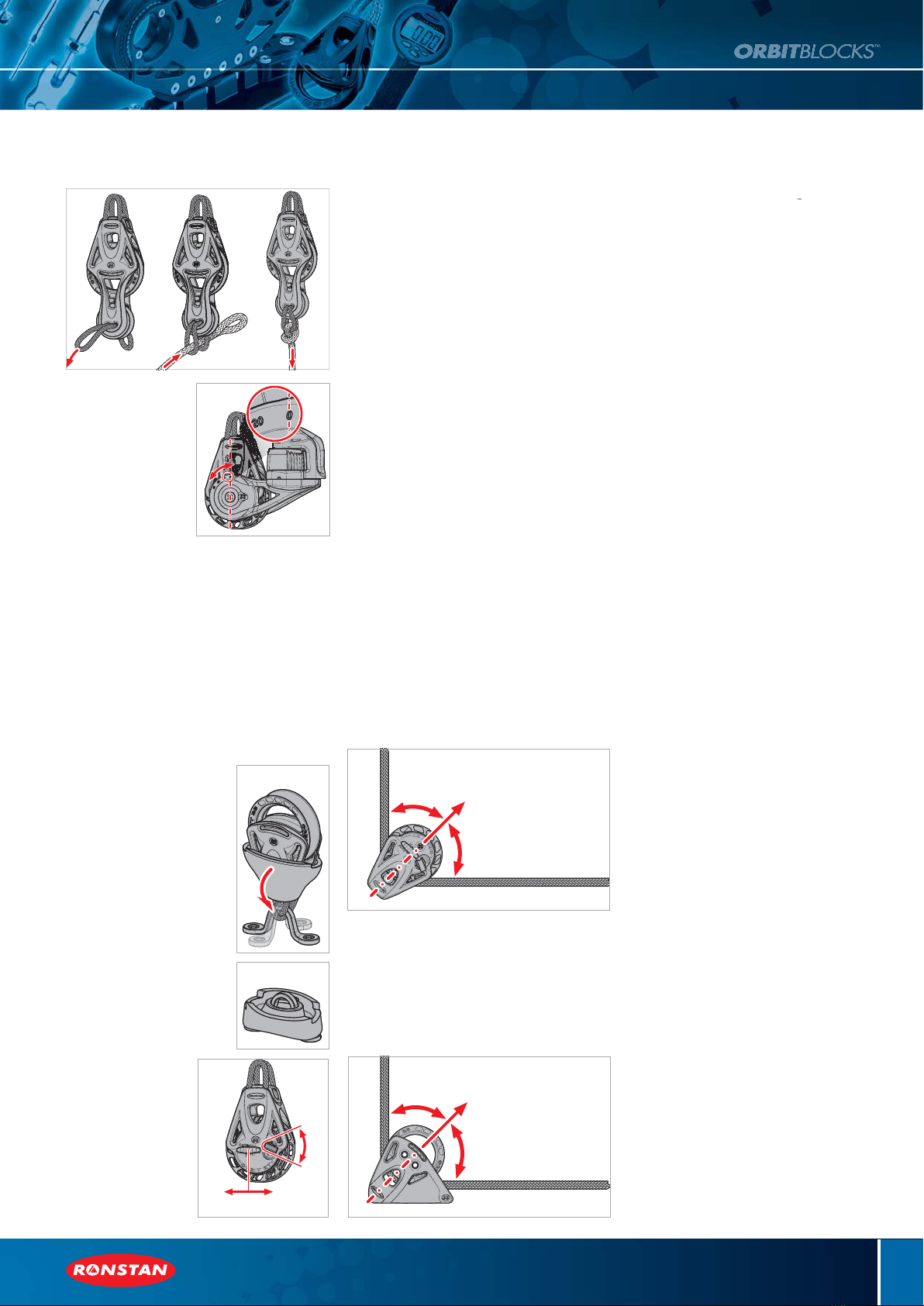
(Diagrams 2.3B)
I
using a pre-spliced sheet, secure with a cow
hitch through both loops o
the Link
.
(Diagram 3.0)
Ad
ustment of
leat arm an
le
.
.
n t
r
w at t
ntr
f th
l
at arm
n each side of the block
approximately 1 ½ turns
3.0.
djust the cleat arms to the re
uired an
le. The
cleatin
an
le can be adjusted
rom
de
rees
when
the sheet is coming out o
the block at right angles to
the centre line of the block
to 60 degrees
40 degrees
n RT triple, becket
cleat). The cleat arm angle is
ndicated by the number aligned with the centre line of
t
.
3.0.
e-ti
hten the screw at the centre of the cleat arm on
ach side of the block
.
tand-up kit
.0.
se the method described in
.
ab
v
t
t th
link f
r
°
transverse
or
°
in-line
.
.
.
rn t
r
r
t
n
t
nd place it over the head of
t
e
oc
so t
e
n
rotru
es
t
rou
t
e sma
en
.
.0.3 (Diagram 4.0.3)
ass the saddle throu
h the lin
n the re
uired orientation.
.
.
ix the saddle to the mounting
rfa
.
.
(Diagram 4.0.5)
f attaching the block to a fitting
that is alread
fixed in
ace, ro
u
t
e
ottom
alf of the boot to sim
lify
ttachment of the Link
nd unroll it a
ain when
ini
h
d
5.
(Diagram 5.0)
atchet mode
peratio
ome RT
rbit Blocks™
an
t t
t
mat
o
e or
anua
mo
e to su
t t
e a
cat
on or user
s
reference. RT blocks with cleats are fully automatic
onl
.
.
M
n
lM
.
.
T blocks leave the
actory in Manual mode, with
he black MODE switches on both sides of the block
ositioned away from the red
N
FF knob.
.1.
se the red
N
FF knob to turn the ratchet
N or
FF.
5.2
Auto Mod
.
.
With the block in Manual mode, turn the ratchet o
by
otating the red ON/OFF knob to the OFF position
.
.
lide the black MODE switch firmly toward the red
N
FF knob until it locks into the recess in the knob.
epeat with the M
DE switch on the other side of the
oc
.
.
e
oc
s now
n
uto mo
e
.
.4
o return to Manual mode, slide the black MODE
switches on both sides o
the block
irmly away
rom
he red ON
OFF knob. Now use the red ON
OFF knob to
urn the ratchet ON and OFF.
.
(Diagram 6.0)
heek block ali
nment
heek blocks must be properly aligned so that the
axis of the block bisects the angle between line entry
an
ex
t, w
c
must
e approx
mate
y
n t
e same
ane. Misalignment or improper installation will reduce
the load capacity of the block.
7.
(Diagram 7.0)
pr
g
t
ea
oc
a
gnment
The U
ri
ht Lead block is desi
ned to
rovide a
0
de
ree chan
e in line direction, with line entry at
0
degrees to the base and line exit parallel to the base.
ny variation on these line angles will reduce the load
capacity of the block
8.
are and maintenanc
neem
®Link
Ronstan BB and RT Orbit Blocks
feature a unique
yneem
n
ea
.
u
ng on t
e
atest tren
s
n gran
pr
x
ng
y an
ocean rac
ng,
t rep
aces
he steel head
ost and shackle arran
ement of
ra
t
ona
oc
s.
onstan
neema
n
s are
ade from hi
hest
uality F
E Robline
cean 3000
lait Dyneema
SK75 line, treated with S.Y.I.S.
mpregnation
or high resistance to abrasion and UV
rotection. Dyneema
is a super strong polyethylene
ibre that offers maximum strength combined with
n
mum we
g
t.
yneem
fibre’s high tenacity
allows it to match the strength of steel at one tenth
of the wei
ht. It is more durable than
olyester and
as a s
ecific stren
th that is 40
ercent
reate
han aramid fibre.
To receive the maximum
erformance benefit from
he Dyneem
Link, it must be used correctly,
nspected regularly and replaced when required.
The Dyneema
Link must be attached to a mounting
oint with a smooth, well rounded profile without
sharp edges or burrs. If in doubt, use a shackle
ith a
m
th
rfa
b
tw
n th
Link and th
ount
n
o
nt.
• The Dyneema®Link will eventually suffer
degradation from fatigue, wear and UV exposure.
Like all running and standing rigging, the Link should
be inspected regularly and replaced it if it shows
significant amount of wear or fibre damage, or as a
part of your regular boat maintenance program.
Orbit Block
Grit and sand will damage bearing systems.
onstan
rbit Blocks™ have a precisely engineered
bearing system that should be kept clean and free of
sand and
rit to ensure o
timum
erformance and
service life. Blocks, in
articular the bearin
areas,
should be flushed with fresh water re
ularly and
eriodically cleaned with a mild deter
ent and water.
Dry lubricants such as Ronstan Sailfast silicon
spray may be used to lubricate the bearing system
and rat
h
t
ntr
l
. Oil/petrochemical based
lubricants must not be used.
Ronstan
rbit Blocks™ are designed and
anufactured for applications on sailboats.
ee
he Info section of the Ronstan web site and our
catalo
ue for im
ortant customer considerations
and warrant
information
.
initi
n
B = Ball Bearin
T = Rat
h
t
WL = Maximum Working Loa
L = Breaking Load
yneem
is a trademark of Royal DSM NV.
M is the inventor and manufacturer of Dyneem
he world’s strongest fibre™.
Dyneema
an
D
neem
, the world’s stron
est fibre™” are
rademark
s
applications
owned by Royal D
M NV.
4.0.3
4.0.5
E
Q
U
A
L
E
Q
U
A
L
6.0
E
Q
U
A
L
E
Q
U
A
L
7.0
3.0
2.3B
ON
OFF
AUTOMANUAL
5.0


