Emco V-20 User manual


GENERAL DESCRIPTION
The EMCOModelV-201s a high quality, 31 range multimeter, provided with a 50 microampere, D’Arsonval meter
movement to give a sensitivity of 20,000 ohms per volt on DC and 1000 ohms per volt on AC. This high sensitivity
results in light loading and, therefore, minimum disturbance in the circuit under test, an indispensable feature for
accurate measurement. The quality of this instrument is further exemplified by the inclusion of wire-wound
potentiometers (shunting and in series with the rectifier), which are factory adjusted to compensate for the individual
characteristics of the rectifier in your instrument. This built-in EMCO feature assures you of standardized accuracy
over a wide range of measurements.
This instrument provides AC and DC voltage measurement from .1 volt (on the 2.5 volt scale) to 5000 volts (an internal
high voltage multiplier is included). It also provides DC current measurement from 1 microampere (on the 50
microampere scale) to 10 amperes. Resistance ranges to 20 megohms, output, and decibel ranges bring the total number
of useful ranges to 31. An added feature of this instrument is an internal blocking capacitor that can be switched when
it is desired to measure the output signal voltage in circuits where DC is present.
Easy reading with less probability of error is obtained with a large 4-1/2" meter. The instrument is ruggedly housed in a
polished, high-impact bakelite case with a genuine leather carrying handle.
These instruments have the wide scope of ranges, sensitivity, and accuracy that are necessary in television, f-m, and a-
m servicing and manufacture. They are simply operated, easily read, and rugged enough for hard daily use.
SPECIFICATIONS
Ranges
DC Voltage 0 to 0.25, 2.5, 10, 50, 250, 1000, 5000 volts at 20,000 ohms per volt
AC Voltage 0 to 2. 5, 10, 50, 250, 1000, 5000 volts at 1000 ohms per volt
DC Current 0 to 50 ua, 10 ma, 100 ma, 500 ma,
10 amperes ( 250 millivolt drop across the meter)
Output Voltage 0 to 2.5, 10, 50, 250, 1000, 5000 volts (. 1 mfd internal series capacitor)
1

Decibels -12 to -55 db in 5 ranges (calibrated for use across a 500 ohm line
Resistance Range Center Scale
0 to 2000 ohms (12 ohms)
0 to 0.2 meg (1200 ohms)
0 to 20 megs (120,000 ohms)
Overall Dimensions 6-3/4" X 5-1/4" X 3"
Weight 2-3/4 pounds with batteries
Cabinet Highly polished black Bakelite
Panel Highly polished black Bakelite
Meter 4-1/2 inch face, 50 ua movement
OPERATING INSTRUCTIONS
Zero Adjustment
The slotted screw directly beneath the meter face is used to adjust the position of the meter pointer if it is off zero
(when no measurement is being made). To bring the meter pointer to zero, use a small screwdriver to turn the screw
either right or left as is necessary. This adjustment should be made before taking readings.
D-C Voltage Measurement
a. Set the DC-AC-OUTPUT switch to the DC position.
b. Set the RANGE switch to the voltage range that you can reasonably expect will include the voltage you are
measuring. If you are in doubt about the voltage present, always set the switch at the highest voltage range before
applying the unknown voltage to the instrument. Failure to observe this precaution may result in serious damage to the
meter. If the unknown voltage is too low for accurate measurement on the highest range, rotate the RANGE switch
towards the lowest voltage position until the range is found at which the voltage can be read accurately.
c. When a voltage is being measured on any range except the 5000 volt range, insert the test leads in the jacks
marked + (POSITIVE) and - COMMON. Place a test lead at each of the two points between which the DC voltage is to
be measured, observing polarities. If you have mistaken the polarities, the pointer will be deflected left of zero, in
which case simply reverse the test leads.
d. Voltages in either the 1000 or the 5000 volt range are measured with the RANGE switch in the 1KV-5KV
position. To use the 5000 volt range insert the test leads in the pin Jacks marked - COMMON and D. C. 5000 V.
CAUTION: Extreme care must be exercised when making measurement on the 5000 volt range, as high voltage is
dangerous. Never fail to turn off the
2

power when connecting or disconnecting the test leads. The meter and the leads must not be handled while the power is
on.
e. DC voltages are read on the black 0-10, 0-50, 0-250 scales marked D.C. When using the 10, 50, and 250 volt
ranges, the meter may be read directly. To obtain the indicated voltage in volts on the 2.5 volt range, divide the reading
on the 250 scale by 100. For readings on the 0.25 volt range, divide the reading on the 250 scale by 1000. On the 1000
volt range, multiply the reading on the 10 scale by 100; on the 5000 volt range, multiply the reading on the 50 scale by
100 to obtain the indicated voltage in volts.
AC Voltage Measurement
The instructions for AC voltage measurement are the same as those for DC voltage measurement, with the following
differences in procedure and reading.
a. Set the DC-AC-OUTPUT switch to the AC position.
b. To use the 5000 volt range, insert the test leads in the pin jacks marked "-" COMMON and A.C. 5000V.
CAUTION: Extreme care must be exercised when making measurement on the 5000 volt range, as high voltage is
dangerous. Never fail to turn off the power when connecting or disconnecting the test leads. The meter and the leads
must not he handled while the power is on.
c. Read the red 0-10, 0-50, 0-250 scale marked A. C. on all voltage ranges except the 2.5 volt range, which is read
on the red 0-2.5 scale marked 2.5V.A.C.
d. The reading of the meter scales corresponding to each range position is the same as for DC with the exception
of the special 2.5V.A.C. scale, which is numbered in tenths of a volt.
DC Current Measurement
CAUTION: Never place the instrument across a voltage source when it is set for current measurement. Failure to
observe this precaution may result in serious damage to the meter.
a. Set the DC-AC-OUTPUT switch to the DC position.
b. Set the RANGE switch to the current range that you can reasonably expect will include the current you are
measuring. If you are in doubt about the current present, always set the switch at the highest current range before
inserting the instrument in the circuit. Failure to observe this precaution may result in serious damage to the meter. If
the unknown current is too low for accurate measurement on the highest range, rotate the RANGE switch towards the
lowest current position until the range is found at which the current can be read accurately.
c. When a current is being measured on any range except the 10 amp. range, insert the test leads into the pin jacks
marked + (POSITIVE) and - COMMON and place the instrument in series with the component through
3

which the current to be measured is flowing (observing current direction). If you have mistaken the direction of current
flow, the pointer will be deflected left of zero, in which case simply reverse the test leads.
d. Currents in either the 10 ma range or the 10 amp. range are measured with the RANGE switch in the 10MA-
10AMP. position. To use the 10 amp. range, insert the test leads in the pin jacks marked +10 AMP and -10 AMP,
taking care to observe the direction of current flow.
e. DC currents are read on the black 0-10 and 0-50 scales marked D. C. When using the 10 ma and 10 ampere
ranges, read the 10 scale directly in ma and amperes, respectively. To obtain the indicated current on the 100 ma range,
multiply the reading on the 10 scale by 10 and read ma. Read the 0-50 scale directly for measurements made on the 50
ua scale. On the 500 ma scale, multiply the reading on the 50 scale by 10 and read in ma.
Resistance Measurement
a. Set the DC-AC-OUTPUT switch to the DC position.
b. If you are measuring a resistance less than 150 ohms, set the RANGE switch at the RX1 position. For a
resistance between 150 and 15,000 ohms, use the RXI00 position; and for s resistance above 15,000 ohms, use the
RX10K position.
c. Insert the test leads into the Jacks marked + (POSITIVE) and - COMMON.
d. To zero adjust on any range, short the test leads and rotate the ZERO OHMS knob until the meter pointer is set
directly over the zero of the top black scale marked OHMS.
e. Connect the test leads across the component whose resistance is to be measured. On the RX1 range, read the
scale directly in ohms, To obtain the indicated resistance in ohms on the RX100 and the RX10K ranges, multiply the
scale reading by 100 and 10,000, respectively.
Output Voltage Measurement
The instructions for output voltage measurement are the same u those for AC voltage measurement, with the exception
that the DC-AC-OUTPUT switch is set at the OUTPUT position.
Consideration should be given, however, to the effect of the blocking capacitor when measuring on the 2.5V range at
frequencies less than 1000 Hz, the 10V range below 250 Hz, and the 50V range below 60 Hz. On these ranges, below
the frequencies given, the ratio of the reactance of the blocking capacitor to the multiplier resistance for the range is too
high to neglect the bleeding of the applied voltage by the blocking capacitor. The graph in figure 1 has been prepared
so that measurement can be made in these cases. The graph is used in the following way:
4

a. Find the point corresponding to the frequency of the applied voltage on the horizontal scale marked "cycles per
second.”
b. Trace upwards from that point until you strike the curve corresponding to the range on which you are
measuring.
c. Trace along the horizontal line from that point until you strike the vertical scale marked "correction factor."
d. Multiply the voltage indicated on the meter by the correction factor obtained from the graph to find the true
voltage.
DB Measurement
The instructions for db measurement are the same as those for AC voltage measurement, except for the reading of the
meter scales.
When using the 2. 5 volt position, the DB scale is read directly; for all other ranges it will be necessary to algebraically
add the number of db charted on the right hand side of the meter face. For example, if the RANGE selector switch is set
at 250 volts and the meter indicates + 1DB, the actual reading would be 40 + 1 = 41db. As a further example, if the
meter in the 10 volt position reads -8DB, the actual reading would be -8 + 12 = 4db.
5

Capacitance and Inductance Measurements
NOTE: An external AC power source is required to make
capacitance and inductance measurements.
1. Set up the MODEL V-20 and the external power source as shown in figure 2.
WARNING:
Make certain the external power source is off before connecting the capacitance or inductance to be measured.
2. For capacitance readings of .009 MF to 1MF or for inductance readings, set the DC-AC-OUTPUT switch to AC
and the RANGE switch to 10V, and (with the meter leads connected across the secondary of the power transformer)
adjust the external power source for a full-scale reading of 10 volts rms. For capacitance readings of .0001 MF to. 03
MF, set the RANGE switch to 250V, and adjust the external power source for a full-scale reading of 250 volts rms.
CAUTION: Adjust the external power source starting from its lowest voltage so as not to overload the meter on the
selected scale.
3. With the capacitance or inductance in series with the secondary of the power transformer, as shown in figure 2,
read the voltage on the meter; then refer to table 1 (capacitance of .009 MF to IMF), table 2 (capacitance of. 0001 MF
to .03 MF), or table 3 (inductance of 5H to 1000H) to ob/n t-the corresponding value of capacitance or inductance.
6


High Resistance Measurements
NOTE: An external DC power source variable up to 250V; a 270K,
5% resistor; and a 180K, 10% resistor are required to
make high resistance measurements.
1. Set up the Model 565 (555) and the external components and power supply as shown in figure 3.
9

WARNING: Make certain the external power source is off before connecting the resistance to be measured
2. Set the DC-AC-OUTPUT switch to the DC position and the RANGE switch to the 250V position.
3. Adjust the DC power source for a full-scale reading of 250 volts with the meter leads connected across resistor
Rl. Make certain not to overload the meter.
4. With the high value resistor to be measured connected in series with resistor R1, as shown in figure 3, read the
voltage on the meter; then refer to table 4 to obtain the corresponding resistance value.

CIRCUIT THEORY
Introduction
The purpose of this section is to describe the theory of operation of each of the measuring circuits available with this
instrument. Simplified individual schematic diagrams accompany each of the circuit descriptions.
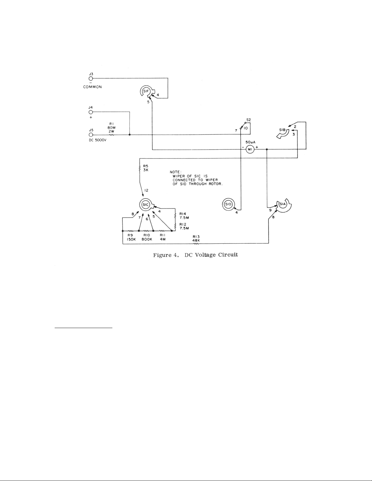
DC Voltage Measurement
Figure 4 shows that portion of the 565/555 meter circuit used for DC voltage measurements. Contacts 7-10 of
OUTPUT-AC-DC function switch S2 are closed in this mode. Jacks J3 ( - COMMON) and J4 (+) are used to measure
all voltage ranges except 5KV. In this case jacks J3 and J5 (D. C. 5000 V.) are used. Deck C of RANGE switch S1 is
used to select the resistance that must be placed in series with meter M1 so that the meter will provide the proper
reading for the selected range scale. The rotor of S1C is connected to the rotor of S1D, so the selected resistor is placed
in series with M1 through S1D-4. The following contacts of SIC represent the six available voltage ranges: 4 -
1KV/SKV; 5 - 250V; 6 - 50V; 7 - 10V; 8 - 2.5V; 12 - 0.25V.
11
The meter is fully deflected by a current of 50 ua. Therefore the value of the total series resistance for each range
should be equal to the voltage of the range divided by 50 ua (Ohm's Law: R = E/I). For example, for the 50V range, the
series resistance should be 1 Meg. If the series circuit is traced between J3 and J4 (with SI C on contact 6), it will be
found that the resistance will total 1 Meg. (Include 2K for the resistance of the meter.) The same is true for each of the
remaining voltage ranges. When the 5000 volt range is used and the measurement is made between J3 and J5, an
additional 80 Meg resistor is added to the series circuit to provide the required 100 Meg for this range. When actual
voltage measurements are made, any voltage less than the selected range will provide a meter deflection
proportionately less than full scale.
AC Voltage Measurement
Figure 5 shows that portion of the V-20 meter used for AC and output voltage measurements. Contacts 8-10 and 2-4 of
function switch S2 are closed for AC measurements. Here again, jacks J3 and J4 are used to measure all AC voltages
except 5KV, in which case J3 and J6 (A.C. 5000 V.) are used. Deck E of RANGE switch S1 is used to select the
resistance that
12

must be placed in series with meter MI so that the meter will provide the proper reading for the selected range scale.
The following contacts of S1E represent the five available voltage ranges: 8 - 1KV/5KV; 9 - 250V; 10 - 50V; 11 - 10V;
12 - 2,5V.
Since the meter deflects only in proportion to the average current level passing through it (and the average value of AC
is zero), the current drawn by the instrument is rectified by a full-wave rectifier circuit consisting of diodes D1 and D2.
The resulting current is a pulsating DC whose average value is proportional to the applied AC voltage. The current-
resistance characteristics of the diodes makes it impractical to try to obtain accurate readings at low currents. Therefore
the instrument is designed to draw about 20 times the current for a measurement of AC voltage as it does for an
equivalent DC voltage measurement. Since the DC sensitivity of the meter is 20,000 ohms/volt, the AC sensitivity is
1000 ohms/volt. Potentiometers R20 and R21 in the rectifier circuit are factory adjusted to provide proper readings with
the RANGE switch in the lowest and highest voltage positions, respectively. The series resistors selected by S1E have
the
13

same proportion to each other for the various ranges as the series resistors selected by S1C for the DC voltage circuit,
except that the AC series resistors are 1/20 the value of the DC resistors.
Resistance Measurement
Figure 6 shows that portion of the V-20 meter circuit used for resistance measurements. With the unit used as an
ohmmeter, function switch S2 is in the DC-OHMS position and contacts 7-10 are closed. Resistance measurements are
made between jacks J3 and J4.
The voltage used for the resistance measurements is selected by deck C of RANGE switch S1. The R x 1 and R x 100
ranges use 1.5 volts through contacts 1 and 2 of SIC and contact 4 of SID (wipers of SIC and SID are connected
together); while the R x 10K range uses an additional 6 voIts (contact 3 of SIC). Meter M1 is located in one leg of a
parallel resistance network consisting of resistors R16, R17, R18, H19, and R27. Decks E and F of S1 are used to select
the proper combinations of these resistors for each
14

of the selected ranges. Potentiometer R28 is used to compensate for variations in the battery voltages, thus allowing the
meter to be zeroed for each range.
DC Current Measurement
Figure 7 shows that portion of the V- 20 meter circuit used for DC current measurements. In this mode, function switch
S2 is in the DC-OHMS position; and contacts 7-10 are closed. Jacks J3 and J4 are used for all current ranges except the
10 AMP range, in which case jacks J1 and J2 are used.
As in the resistance measurement circuit, meter MI is located in one leg of a parallel resistance network. The
combination of resistors is selected by decks A, B, and C of RANGE switch SI. The higher the current range selected,
the less resistance is placed in parallel With the circuit containing MI, thereby shunting most of the current away from
the meter. However, in the 50 ua range position, there is no shunt leg and all current is passed through the meter (50 ua
is required for full-scale deflection). In the 10 AMP range (when jacks J1 and J2 are used), the shunt circuit consists
only of .025 ohm resistor R4. Jacks J1 and J2 are used in the 10 AMP range to reduce the number of switch contacts
through which high currents must pass.
Output Voltage Measurement
The output voltage measurement circuit (figure 5) description is the same as that listed in the preceding AC section,
except that contacts 9-10 and 3-4 of function switch S2 are closed and capacitor C1 is used to block any DC component
present.
15

Decibel Measurement
The operation of the DB range (see figure 5) is essentially the same as that described under Output Voltage
Measurement. The meter is calibrated in DB across a 500 ohm impedance.
MAINTENANCE
General
This instrument should require very little, if any, maintenance due to its inherent ruggedness and ability to withstand
electrical surges. Care should be taken, however, to protect the instrument from any severe mechanical or electrical
shock.
When in doubt of the voltage or current present in the circuit, always use the highest range and then proceed downward
until the meter reads somewhere between 1/5 and full scale.
Battery Replacement
When it is no longer possible to zero the meter on the R x 1 and R x 100 ranges by rotating the ZERO OHMS knob
with the test leads shorted, the single, large 1.5 volt battery should be replaced.
When it is no longer possible to zero the meter on the R x 10K range by rotating the ZERO OHMS knob with the test
leads shorted, the four small 1.5 volt batteries should be replaced.
Both types of batteries are standard and readily obtainable. The large battery is of the flash light type, and the small
batteries are of the pen light type.
NOTE: When replacing batteries, make certain that polarities are observed as shown in the schematic diagram. The
instrument may be taken out of its case by removing the two screws on the front panel and the single screw on the rear
of the case.
16

MODEL V-20
Please add the following to your OPERATING MANUAL. On page 2, after the title OPERATING INSTRUCTIONS,
insert the following paragraph:
Before proceeding, remove the instrument from the cabinet. Insert a large flashlight battery. D-Cell, into the battery
bracket mounted on the wall of the bakelite case The Positive terminal of the battery is to face up towards the top of the
case. Now insert the four penlight batteries, AA-cells, into the battery bracket mounted on the meter. Adjacent batteries
are to be inserted in opposite directions. Thus, the battery closest to the large 2 Megohm resistors, is inserted with the
positive terminal up towards the top of the panel. The next battery is inserted with the positive terminal down. The third
battery is inserted into the bracket with the positive terminal up while the battery located furthest from the resistors, is
inserted with the positive terminal down.
Replace and secure the VOM panel in its cabinet.
If you have a kit please make the following changes:
Page 6, Fig. 1
A rectangular pot is shown on right end of resistor board, redraw it so that it is at the left end.
PAGE, 7 STEP 2, CHANGE WIRE LENGTH FROM 1-1/2” TO 1-3/4”
PAGE 13 STEP 8, CAPACITOR LEAD LENGTH SHOULD BE OUT TO 3/4"
PLEASE NOTE:
R 12 AND R 14 (part no. 11035) BOTH 7.5 Meg. RESISTORS WHICH ARE USED IN SERIES TO MAKE
15 MEGOHM 1% ARE NOW ANY TWO VALUES TOTALING 15 MEGOHMS 1%. THEY ARE PACKED IN A
SMALL ENVELOPE MARKED R12-R14 PART NO. 11035.
I.E. 2335
ADMENDMENT
19

Schematic
20
This manual suits for next models
1
Table of contents
Other Emco Measuring Instrument manuals

Popular Measuring Instrument manuals by other brands


Lovibond
Lovibond EC 2000 Gardner Operator's instruction manual

Fluke
Fluke 481-DESI Technical data

PCB Piezotronics
PCB Piezotronics IMI SENSORS 683A001000 Installation and operating manual

Dawson
Dawson DAM100B user manual

FineTek
FineTek EPR5 Operation manual

SICK
SICK TRANSIC Extractive operating instructions


