JEWELL TuffTilt Digital User manual

B-06-1006, Rev. E Tuff Tilt Digital 1
TUFF TILT DIGITAL TILTMETER
TABLE OF CONTENTS
1 - INTRODUCTION......................................................................................................................................2
2 - INSTALLING THE TILTMETER, MAKING CONNECTIONS, TILT DIRECTIONS.......................... 6
3 - POWER REQUIREMENTS AND GROUNDING .............................................................................. 6
4 - COMMUNICATING WITH THE TUFF TILT ..................................................................................... 9
4.1 Basic Requirements and Settings ........................................................................................... 9
4.2 Firmware Command Format..................................................................................................... 9
4.3 Firmware Command Summary............................................................................................... 10
4.4 Sample Data Using the XY Command................................................................................... 12
5 - MAINTENANCE AND TROUBLESHOOTING ............................................................................... 13
APPENDIX A - FIRMWARE COMMANDS.......................................................................................... 14
APPENDIX B - ZAGI GRAPHICAL INTERFACE SOFTWARE (Installation & Operation) .............. 28
1 Introduction................................................................................................................................. 29
2 System Requirements................................................................................................................ 29
3 Installing ZAGI ............................................................................................................................ 29
4 Configuring Communications................................................................................................... 30
5 Data Access ................................................................................................................................ 31
6 Command Line Menu Options .................................................................................................. 32
7 Screen Options........................................................................................................................... 33
8 Equivalent Firmware Commands.............................................................................................. 34
9 Event Markers; Plotting Saved Files ........................................................................................ 35
10 Data Logging to Tiltmeter Memory........................................................................................... 35
11 Data File Format......................................................................................................................... 36
12 Printing........................................................................................................................................ 37
APPENDIX C - WARRANTY AND LIMITATION OF LIABILITY......................................................... 39
APPENDIX D - REVISION RECORD................................................................................................... 41
LIST OF FIGURES:
Figure 1: The Tuff Tilt Digital ............................................................................................................... 2
Figure 2: Instrument Mounting Hole Locations.................................................................................... 3
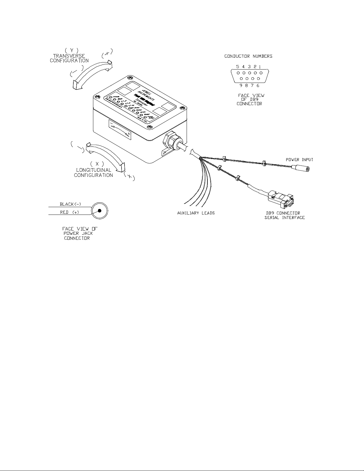
Figure 3: Cable Termination Detail...................................................................................................... 4
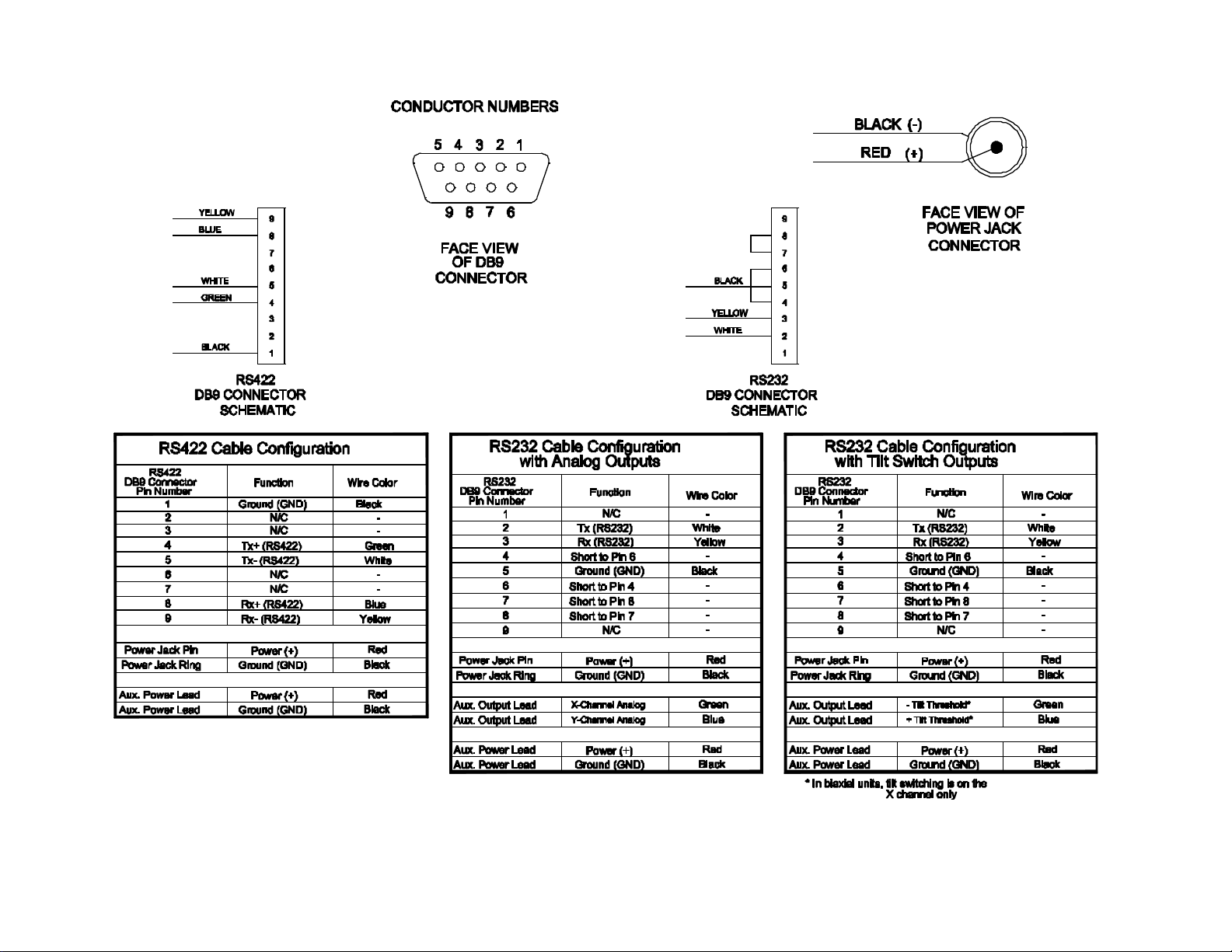
Figure 4: Wiring Connections .............................................................................................................. 5
Figure 5: Installation Methods.............................................................................................................. 7
Figure 6: Box Mounting Details............................................................................................................ 8

B-06-1006, Rev. E Tuff Tilt Digital 2
1 Introduction
The
Tuff Tilt Digital
is an exciting new digital instrument for indoor and outdoor work requiring precision and
rugged durability. It is excellent for continuous monitoring of structural behavior, or short-term testing of
machine and structural performance. It fills a gap between our economical MD900-T Digital Clinometer and
our Model D711 Scientific Tiltmeter.
The
Tuff Tilt Digital
is offered with many powerful features, including: RS232 output, RS422 output, analog
output or optional tilt switch output in the RS232 versions, biaxial or uniaxial measurement, and 16-bit A/D
resolution. The serial data output is easily interfaced to many GPS receivers, spread spectrum radios, and
wireless Ethernet converters. A powerful set of firmware commands enables the user to collect, process and
store data, or to send data directly to external devices.
Figure 1.
Tuff Tilt Digital

B-06-1006, Rev. E Tuff Tilt Digital 3
Tuff Tilt Digital
(Standard)
Tuff Tilt Digital
(Wide Angle)
ANGULAR RANGE
±3 degrees
±50 degrees (greater range available)
RESOLUTION
0.0001 degree
0.002 degree
REPEATABILITY
0.0003 degree (1 arc second), static
0.004 degree, static
TEMPERATURE COEF.
Zero: ±0.0002 degree/°C typical
Zero: ±0.004 degree/°C typical
CHANNELS
Single-axis or dual-axis with 2 orthogonal tilt channels, 1 temperature channel
LINEARITY
< 0.1% of full span
TIME CONSTANT
0.15 second
DIGITAL OUTPUT
RS232 or RS422, transmit and receive
Baud rate: 9600 (default), 19200, 28800, 57600, 115200, 230400
NMEA 0183 compatible (x, y, temperature, serial no.), plus other output strings
OUTPUT DATA RATE
User-selectable from 10 samples/second to 1 sample/24 hours
POWER REQ’TS
7-28 VDC @ 30 mA, 250 mV peak-to-peak ripple maximum, reverse polarity protected
ENVIRONMENTAL
25° to +70°C operational, 30° to +100°C storage. NEMA 4X (IP65)
MOUNTING
Four no. 8 stainless steel mounting screws included
MATERIALS
Die cast and painted aluminum
CABLE & CONNECTOR
3m (10 ft), 6 conductors + one overall shield, PVC jacket. DB9 connector for digital I/O.
SIZE & WEIGHT
120 x 80 x 60 mm (4.7x 3.2 x 2.4 inches), 0.6 kg (1.5 lb)
Figure 2. Mounting holes are accessed by removing lid of tiltmeter.
Use 8-32 or 4 mm screws.

B-06-1006, Rev. E Tuff Tilt Digital 4
Figure 3. Cable termination details: Tinned ends (left) for power and optional analog or tilt switch output,
DB9 connector for serial communications, and barrel connector for power input using optional power supply
part no. 00254-02.

B-06-1006, Rev. E Tuff Tilt Digital 5
Figure 4. Wiring connections, Tuff Tilt Digital

B-06-1006, Rev. E Tuff Tilt Digital 6
Description & Order Numbers
Communications Protocol
RS232*
RS422
±3 degrees, Uniaxial, Transverse
98943-09
98943-10
±3 degrees, Uniaxial, Longitudinal
98943-07
98943-08
±50 degrees, Uniaxial, Transverse
98943-15
98943-16
±50 degrees, Uniaxial, Longitudinal
98943-13
98943-14
±3 degrees, Biaxial
98943-11
98943-12
±50 degrees, Biaxial
98943-17
98943-18
* RS232 version is available with optional analog X, Y output or tilt switch output. Please specify when ordering.
Accessories
Order No.
Extra cable
70369
Horizontal mounting plate
84051
Vertical mounting bracket
81439
Power supply (110-240 VAC)
00254-02
2. Installing the Tiltmeter, Making Connections, Tilt Directions
For best results, the tiltmeter should be fastened to a rigid metal or concrete base using four machine
screws (no. 8 or M4 size). To access the four mounting holes, first remove the lid of the clinometer (Figure 2).
The base to which you will attach the clinometer should be drilled in advance with four threaded or through
holes. Use a bolt anchoring system if the base is concrete. The hole pattern must match the 107 x 67 mm hole
mounting hole pattern of the clinometer. For stable readings, the mounting screws should hold the clinometer
tightly against the base so that it cannot shift or wobble. Replace the lid when installation is complete. Note:
Our horizontal mounting plates and vertical mounting brackets simplify the installation. See the accessory
table above and also Figure 5.
To operate your clinometer, connect the cable assembly as shown in Figure 4. Provide power by
connecting the transformer to the power input connector, or use the auxiliary power leads and a separate power
supply. Connect the DB9 serial interface connector to a PC or terminal and then follow the instructions in
Section 4. Tilt directions are shown in Figure 3.
3. Power Requirements and Grounding
Your Tuff Tilt Digital operates on 7-28 volts DC and draws approximately 30 mA of power. Power
and ground are connected at pins 2 and 1 respectively of the 6-pin connector. See Figure 4 for wiring details.
The enclosure (case) is not grounded except through tranzorbs used for surge protection.
Transient surge absorbers (tranzorbs) connect the power, ground, RS232 and RS422 pins to the case.
Screwing the case to a metal substrate at the four mounting holes will ground the case (Figures 2). If the
substrate is grounded to the earth, high-voltage transients traveling down the clinometer cable will have a path

B-06-1006, Rev. E Tuff Tilt Digital 7
to earth ground, reducing the likelihood of damage to the circuitry.
Installing the Tuff Tilt Digital on Vertical Surfaces
Installing the Tuff Tilt Digital on Horizontal Surfaces
Note: The tiltmeter enclosure may also be screwed directly to the mounting surface
without use of the P/N 84051 Mounting Plate
Figure 5. Installation Methods

B-06-1006, Rev. E Tuff Tilt Digital 8
Figure 6. Box Mounting Details

B-06-1006, Rev. E Tuff Tilt Digital 9
4. Communicating with the Tuff Tilt Digital
4.1 Basic Requirements and Settings
You may communicate with your tiltmeter using:
1. ZAGI Software (supplied with the tiltmeter) and a personal computer running Microsoft Windows;
2. A terminal emulator program (e.g. Terminal in Windows 3.1 or HyperTerminal in Windows 95 and
later); or
3. A GPS receiver that is capable of sending and receiving terminal commands.
All communication to the tiltmeter is performed through the send (transmit) and receive wires of the
serial port. The default parameters for the serial port are set to no parity, 8 bits and 1 stop bit with no
hardware or software flow control. The baud rate is the only parameter that is user-selectable. The default
baud rate is 9600. Baud rates up to 230400 are supported.
4.2 Firmware Command Format
The format of commands issued by the host is:
*9900<command><CR><LF>
Valid commands are listed in Appendix A.
The input/output processing on the serial port of the Tuff Tilt Digital is as follows:
(1) Input is read until a <CR> or <LF> (carriage return or line feed) is received. (On a PC, this usually
means pressing the ‘Enter’ or ‘Return’ key.)
(2) When a line is received, it is parsed to see if it is a command of the device. If it is not, then it is
echoed back out, terminated with a <CR> <LF> and we go back to step (1). All strings that are not
commands for the unit are echoed. If the command is for the device, we then go to step (3).
(3) The command is processed and we return to step (1). All incoming characters are buffered (up to
1000) while the command is being processed. If the command is for ID 99 and echoing of 99
commands is enabled, the command is echoed after the command result is transmitted.

B-06-1006, Rev. E Tuff Tilt Digital 10
Default output running firmware version 5 and above is a simple (“SIM”) comma-delimited string consisting
of X tilt in degrees, Y tilt in degrees, temperature in ºC, and the serial number of the device. Optional outputs
consist of a Trimble Navigation proprietary ASCII string with X (Roll) and Y (Pitch) tilts in degrees, and two
output formats that follow NMEA Standard 0183, version 2.1, October 15, 1995. This standard may be
obtained from:
National Marine Electronics Association (NMEA)
National Office
P.O. Box 3435
New Bern, NC 28564-3435 USA
Tel: 919/638-2626
Fax: 919/638-4885
4.3 Firmware Command Summary
The list below summarizes the most important user-accessible firmware commands. Precede these commands
with the string *9900. See Appendix A for additional details.
XY Outputs a single tilt and temperature measurement. The format of the output
depends on the setting of the SO command.
SO-xxx Selects the output format for the XY command. “xxx” selects format as follows:
ASH: Ashtech compatible NMEA format
SIM: Simple x,y,t,sn output string (default)
XDR: NMEA XDR format
TCM: Trimble Navigation proprietary pitch (Y) and roll (X) string
BAE: BAE Systems encoded 11-byte string containing a sync packet, x, y, t,
SN, and checksum information. Advanced users only—typically for
embedded system integration.
XY-MEMS Stores tiltmeter readings at selected output rate in nonvolatile memory.
(Versions 5.1 and higher)
XY-MEMD Downloads data from nonvolatile memory. (Versions 5.1 and higher)
XY-M1 Sets the tiltmeter to Mode-1 operation.
XYVR Displays the sign-on string.
ID Sets the ID of units in the daisy chain (not currently implemented).
XY-TR-PASH-ON Translates the Paros provided $PASHS,XDR,P sentences to standard
NMEA XDR format.
XY-TR-PASH-OFF Turns off translation of $PASHS,XDR,P sentences.
XY-EP Enables power on message.

B-06-1006, Rev. E Tuff Tilt Digital 11
XY-SP Disables power on message.
XY-EE Enables echoing of global 99 commands.
XY-SE Disables echoing of global 99 commands.
XY-SET-BAUDRATE,xSets baud rate to value of xin bits per second. Selectable values include 9600,
19200, 28800, 57600, 115200 and 230400 baud.
XY-SET-N-SAMP,x Sets number of samples that are averaged before a reading is transmitted;
xmay have any value from 1 to 1000. Changing this value may also change the
output rate.
XY-SET-RSMODE,x Selects serial output mode:
x= 0 RS232
x= 1 RS485 (RS422)
XY-AUTOZ Turns on auto zero function.
XY-AUTOZOFF Turns off auto zero function.
XYCxContinuously sends XY data where xdetermines output rate as follows:
x= 0: 8-10 outputs per second
x= 1: 4 outputs per second
x = 2: 1 output per second (default)
x = 3: 1 output every 10 seconds
x = 4: 1 output every 60 seconds
x = 5: 1 output every hour
x = 6: 1 output every 12 hours
x = 7: 1 output every 24 hours
x = 0A: Averaging of the 8-10 outputs per second data
x = 1A: Averaging of the 4 outputs per second data
x = 2A or x= A: Averaging of the 1 output per second data
Once initiated, continuous output remains in effect until turned off with the
XYC-OFF command (see below).
XYC-OFF Turns off XYC mode.
XY-SET-CTRL-ON Enables control feature.
XY-SET-CTRL-OFF Disables control feature.
XY-SET-CTRLTEST-ON Sets the control pin high (+5 VDC).
XY-SET-CTRLTEST-OFF Sets the control pin low (0 VDC).
XY-SET-THRESHOLD,x+,x-,y+,y- Sets the control thresholds.

B-06-1006, Rev. E Tuff Tilt Digital 12
XY-SET-HYST,k Sets the control hysteresis.
XY-DUMP-SETTINGS Dumps settings of device.
XY-DUMP2 Dumps extended settings of device.
4.4 Sample Data Using the XY Command
The most commonly used command is the XY command, which returns the X and Y tilt angles in
degrees and the internal temperature of the Tuff Tilt Digital in ºC. The format of the returned data depends on
the setting of the SO command. The returned data are averages of a series of readings. The number of
samples used in the average is set by the XY-SET-N-SAMP command. The following lines illustrate the
format of the data returned by the XY command for the range of possible SO settings:
SO = “ASH.” Ashtech compatible NMEA output string which returns the North-South (Y) and East-West
(X) tilt angle in degrees and the internal temperature of the MD-900-T in ºC:
$PASHS,XDR,A,004.261,D,N,A,004.280,D,E,C,021.288,C,T-N1346
$PASHS,XDR,A,004.261,D,N,A,004.280,D,E,C,021.306,C,T-N1346
$PASHS,XDR,A,004.261,D,N,A,004.280,D,E,C,021.298,C,T-N1346
$PASHS,XDR,A,004.261,D,N,A,004.280,D,E,C,021.332,C,T-N1346
SO = “SIM” (default). Simple X,Y,T,SN output which returns the X and Y tilt angle in degrees and the
internal temperature of the MD-900-T in ºC:
$-00.619,000.023,018.910,N0000
$-00.619,000.023,018.923,N0000
$-00.620,000.024,018.932,N0000
$-00.620,000.023,018.951,N0000
SO = “XDR.” Standard NMEA XDR output string which returns the North-South (Y) and East-West (X) tilt
angle in degrees and the internal temperature of the MD-900-T in ºC:
$YXXDR,A,000.034,D,N,A,-00.625,D,E,C,021.651,C,T-N0000*47
$YXXDR,A,000.034,D,N,A,-00.624,D,E,C,021.675,C,T-N0000*40
$YXXDR,A,000.034,D,N,A,-00.624,D,E,C,021.686,C,T-N0000*4C
$YXXDR,A,000.034,D,N,A,-00.625,D,E,C,021.707,C,T-N0000*45

B-06-1006, Rev. E Tuff Tilt Digital 13
SO = “TCM.” Proprietary Trimble Navigation pitch (Y-tilt) and roll (X-tilt) output string which returns the
tilt angle in degrees and a checksum:
$P-00.907R002.186*1C
$P-00.906R002.183*18
$P-00.908R002.191*15
$P-00.905R002.190*19
SO = “BAE.” Advanced users only, using the D711-2A(4X). BAE Systems encoded 11-byte output
which returns two synchronization bytes, the X (2 bytes) and Y (2 bytes) tilt angle, the internal
temperature of the tiltmeter (2 bytes), the serial number (2 bytes), and a checksum byte:
Uª Ä$é TæUª Ä$ä TáUª Ä$ß TÜUª Ä$é Tæ
The BAE output string is not clearly decipherable by HyperTerminal, which sometimes hides characters
that it has received and cannot understand. Because of this, it is difficult, if not impossible, to interpret
data in this format. The above output string shows four outputs taken from HyperTerminal. The BAE
output string is not selectable using ZAGI.
This encoded output command is typically used to communicate with embedded systems, as they can view
raw data and perform fast translations.
The first synchronization byte is 0x55, the second is 0xAA. The X and Y bytes use 0.0000277 angular
degrees per LSB, hence the total output range of this output mode is limited to the model D711-2A(4X). The
temperature uses 0.004 degrees Celsius per LSB. The serial number is a two byte integer. The checksum
byte is the result of ANDing bytes 2-7 with 255.
BAE output mode reduces the total number of characters per output to 11 bytes, while transferring the same
data as the SIM output mode, which requires 33 bytes. BAE mode also includes checksum and frame
synchronization bytes. Refer to Appendix A, Firmware Commands, to decode the output.
5. Maintenance and Troubleshooting
The Tuff Tilt Digital is packaged in a rugged aluminum box and should provide many years of
trouble-free operation. Best results are achieved by keeping the unit clean, dry and within the stated operating
and storage temperature ranges.
Problems most commonly result from lack of power, or a broken wire or connection. If the unit does
not respond when queried by the host, first verify that it is receiving power. If it still does not respond,
remove the lid and check for loose broken wires or a loose or detached internal connector. If these checks
still do not reveal the problem, contact Jewell Instruments in Manchester, NH for assistance at telephone:
603/669-6400, fax: 603/622-2690 or e-mail: sales@jewellinstruments.com.

B-06-1006, Rev. E Tuff Tilt Digital 14
Appendix A. Firmware Commands

B-06-1006, Rev. E Tuff Tilt Digital 15
Firmware Commands
Valid commands are listed below. Some commands have more than one string to trigger the
command. “tt” stands for the target ID (99) and “ss” stands for the source ID (00). Settings stored in
nonvolatile memory remain in effect until disabled, even after a power cycle.
---------------------------------------
XY Outputs a single tilt measurement. The format of the output
depends on the setting of the SO command.
Syntax: *ttssXY<CR><LF>
Error Strings: None.
Default: N/A
Persistence: N/A
Example:
command: *9900XY<CR><LF>
response: $YXXDR,A,-00.920,D,N,A,-00.210,D,E,C,030.045,C,T-N1212*57
---------------------------------------
SO Selects the output format for the XY command. The possible formats
are:
-SIM
$x.x,y.y,t.t,sn<CR><LF>
| | | |
| | | Serial number
| | Temperature of tiltmeter
| Y-tilt value in degrees
X-tilt value in degrees
Example:
$-00.920,-00.210,030.045,N1212
-XDR
$YXXDR,A,x.x,D,N,A,x.x,D,E,C,x.x,C,T-sn*hh<CR><LF>
| | | | | | | | | | | | | |
| | | | | | | | | | | | | Checksum
| | | | | | | | | | | | Serial number
| | | | | | | | | | | Comment, T for temperature
| | | | | | | | | | Units, C=degrees C
| | | | | | | | | Temperature of tiltmeter
| | | | | | | | Data Type, C=Temperature
| | | | | | | Comment, E for East/West (X) direction
| | | | | | Units, M=microradians, D=degrees
| | | | | X (E)-tilt value
| | | | Data Type, A=Angular
| | | Comment, N for North/South (Y) direction
| | Units, M=microradians, D=degrees,
| Y (N)-tilt value
Data Type, A=Angular
Example:
$YXXDR,A,-00.920,D,N,A,-00.210,D,E,C,030.045,C,T-N1212*57

B-06-1006, Rev. E Tuff Tilt Digital 16
-ASH
$PASHS,XDR,A,x.x,D,N,A,x.x,D,E,C,x.x,C,T-sn<CR><LF>
| | | | | | | | | | | | |
| | | | | | | | | | | | Serial number
| | | | | | | | | | | Comment, T for temperature
| | | | | | | | | | Units, C=degrees C
| | | | | | | | | Temperature of tiltmeter
| | | | | | | | Data Type, C=Temperature
| | | | | | | Comment, E for East/West direction
| | | | | | Units, M=microradians, D=degrees
| | | | | X (E)-tilt value
| | | | Data Type, A=Angular
| | | Comment, N for North/South direction
| | Units, M=microradians, D=degrees
| Y (N)-tilt value
Data Type, A=Angular
Example:
$PASH,XDR,A,-00.920,D,N,A,-00.210,D,E,C,030.045,C,T-N1212
-TCM
$Py.y,Rx.x*hh<CR><LF>
| | |
| | |
| | CheckSum
| Roll= X-tilt value in degrees
Pitch= Y-tilt value in degrees
Example:
$P-00.905R002.190*19
-BAE
abcdefghijk
|||||||||||
||||||||||Byte 10(k): Checksum of bytes 2-7 ANDed with decimal 255
||||||||||
||||||||Byte 8-9(i,j): Serial number in hexadecimal format
||||||||
||||||Byte 6-7(g,h): Temperature in Deg. C. Bits 14 –0 = magnitude
|||||| (LSB bit = 0.004 Deg. C.), Bit 15 = sign
||||||
||||Byte 4-5(e,f): Y Axis Level Data. Bits 14 –0 = magnitude
|||| (LSB bit = 0.0000277 degrees), Bit 15 = sign
||||
||Byte 2-3(c,d): X Axis Level Data. Bits 14 –0 = magnitude
|| (LSB bit = 0.0000277 degrees), Bit 15 = sign
||
|Byte 1(b): 0xAA, 2nd Synchronization Byte
|
Byte 0(a): 0x55, 1st Synchronization Byte

B-06-1006, Rev. E Tuff Tilt Digital 17
Syntax: *ttssSO-<output format><CR><LF>
Error Strings:
ERR XY-SO BAD PARAMETER
<output format> was invalid.
ERR XY-SO PARSE ERROR
Could not parse <output format>.
Default: SIM
Persistence: Setting is stored in nonvolatile memory.
Example:
command: *9900SO-XDR<CR><LF>
response: <none>
---------------------------------------
XY-MEMS Stores the tiltmeter readings in simple format (SO-SIM) at selected
output rate in nonvolatile memory.
Syntax: *ttssXY-MEMS<CR><LF>
Error Strings: None.
Default: N/A
Persistence: Subsequent tiltmeter readings stored in nonvolatile memory
until memory is full. Maximum of approximately 150 lines of data.
Example:
command: *9900XY-MEMS<CR><LF>
response: <none>
---------------------------------------
XY-MEMD Downloads the tiltmeter readings in nonvolatile memory to PC.
Syntax: *ttssXY-MEMD<CR><LF>
Error Strings: None.
Default: N/A
Persistence: Stored tiltmeter readings downloaded at rate of
1 per second to PC in ASCII comma-delimited string.
Example:
command: *9900XY-MEMD<CR><LF>
response: $start:11-11-1997 18:43:09 4/sec
$000.699,-01.022,025.116,N1028
$000.698,-01.021,025.110,N1028
$000.698,-01.022,025.122,N1028

B-06-1006, Rev. E Tuff Tilt Digital 18
---------------------------------------
XY-M1 Sets the operation to Mode 1. This command groups several
other commands together for convenience. The commands that
are issued are:
XY-TR-PASH-ON
XY-SO-XDR
XY-SE
XY-SP
Syntax: *ttssXY-M1<CR><LF>
Error Strings: None.
Default: N/A
Persistence: Setting is stored in nonvolatile memory.
Example:
command: *9900XY-M1<CR><LF>
response: AGI Model D711-2A(4X) Firmware V2.2 SN-N1212 ID01
---------------------------------------
XYVR Displays the sign-on string.
Syntax: *ttssXYVR<CR><LF>
Error Strings: None.
Default: N/A
Persistence: N/A
Example:
command: *9900XYVR<CR><LF>
response: AGI Model D711-2A(4X) Firmware V5.2 SN-N1212 ID01
---------------------------------------
ID This command is not currently supported. Sets the ID of units
in the daisy chain. The first device in the serial chain sets
its ID to the source ID plus one (ss+1), and then outputs a the
ID command to the next device with the source ID set to its new
ID. The target ID of this command must be 99.
Syntax: *99ssID<CR><LF>
Error Strings: None.
Default: 01
Persistence: Setting is stored in nonvolatile memory.
Example:
command: *9900ID<CR><LF>
response: *9901ID<CR><LF>

B-06-1006, Rev. E Tuff Tilt Digital 19
---------------------------------------
XY-TR-PASH-ON Translates the Paros provided $PASHS,XDR,P sentences to
standard NMEA XDR format. An example input PASH string would
be:
$PASHS,XDR,P,1.000123,B,SN123,C,22.12,C,SN123,H,32.11,P,SN123<CR><LF>
The translated string would then be:
$WIXDR,P,1.000123,B,SN123,C,22.12,C,SN123,H,32.11,P,SN123*hh<CR><LF>
Syntax: *ttssXY-TR-PASH-ON<CR><LF>
Error Strings: None.
Default: Off.
Persistence: Setting is stored in nonvolatile memory.
Example:
command: *9900XY-TR-PASH-ON<CR><LF>
response: <none>
---------------------------------------
XY-TR-PASH-OFF Turns off translation of $PASHS,XDR,P sentences.
Syntax: *ttssXY-TR-PASH-OFF<CR><LF>
Error Strings: None.
Default: N/A
Persistence: Setting is stored in nonvolatile memory.
Example:
command: *9900XY-TR-PASH-OFF<CR><LF>
response: <none>
---------------------------------------
XY-EP Enables power on message. Power on message is:
AGI Tiltmeter Firmware V5.2 SN-N1212 ID01
Where V5.2 is the firmware version, SN-N1212 is the serial
number of the device and ID01 is the target's ID.
Syntax: *ttssXY-EP<CR><LF>
Error Strings: None.
Default: On.
Persistence: Setting is stored in nonvolatile memory.
Example:
command: *0100XY-EP<CR><LF>
response: <none>
Table of contents
Other JEWELL Measuring Instrument manuals
Popular Measuring Instrument manuals by other brands

National Instruments
National Instruments SC-2345 Carrier user manual

BIRD
BIRD Termaline 8930 Series Operation manual

Megger
Megger SmartFuse 250 user guide

EUTECH INSTRUMENTS
EUTECH INSTRUMENTS OAKTON DO 110 instruction manual

Klein Tools
Klein Tools ET300 instruction manual

Keysight
Keysight Y1276A Installation notes