manuals.online logo
Brands
  1. Home
  2. •
  3. Brands
  4. •
  5. NIVELCO
  6. •
  7. Switch
  8. •
  9. NIVELCO R-400 User manual

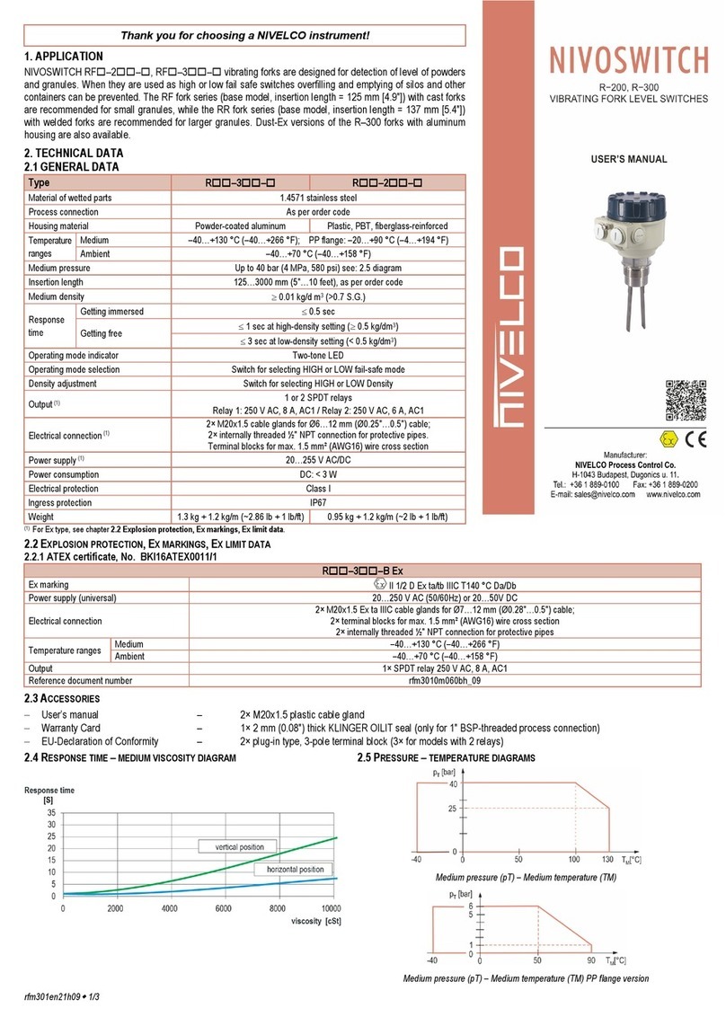
NIVELCO R-400 User manual

rfm400en21h08 ♦ page 1
Thank you for choosing a NIVELCO instrument!
1. APPLICATION
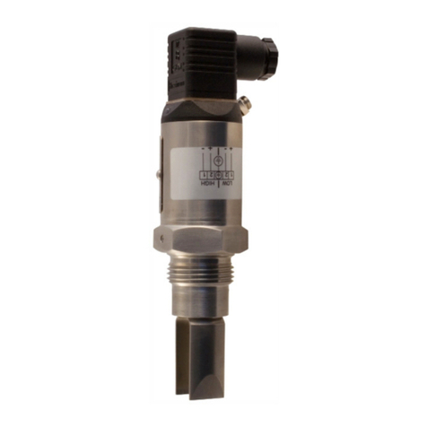
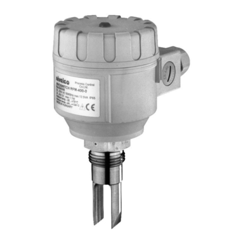
NIVOSWITCH vibrating fork level switches are suitable for level detection of liquids. Mounted on pipes or tanks it
controls lling/emptying, also can generate fail-safe alarms providing overll- or dry run protection. The operating
principle involves an electronic circuit that induces vibration in the fork probe. When the medium reaches and
covers the fork, the vibration changes or stops. The fork will start vibrating freely again when the medium drops to
a level where it no longer touches the prongs. The electronics senses the change in the vibration and sends out
an output signal after a preset delay. The plastic-coated version is recommended for aggressive mediums, the
highly polished version is recommended for abrasive mediums. The ameproof version allows using the device
in Ex rated environments.
2. TECHNICAL DATA
2.1 GENERAL DATA
Type RM–4–Ex,
RN–4–Ex
RD–4–,
RF–4–,
RJ–4–
R–5
Material of wetted parts 1.4571 (316Ti) 1.4571(316Ti) / ECTFE / PFA-coating
Process connection As per order code
Housing material Powder-coated aluminum Plastic, PBT, ber-
glass-reinforced
Temperature
ranges
Medium
See: chapter 2.5.4
–40…+130 °C (–40…+266 °F);
PP ange: –20…+90 °C (–4…+194 °F);
*PFA-coated 1.4571 ange:
–40…+120 °C (–40…248 °F)
(see: diagram 2.3)
Ambient –40…+70 °C
(–40…+158 °F)
–30…+70 °C
(–22…+158 °F)
Medium pressure Up to 40 bar (4 MPa, 580 psi)
(see: 2.3 diagram)
Up to 40 bar (4 MPa, 580 psi) (with PP ange
6 bar [0.6 MPa, 87 psi]) (see: diagram 2.3)
Insertion length 69…3000 mm (2.7″…10 feet), as per order code
Medium density ≥0.7 kg/dm3 (>0.7 S.G.)
Medium viscosity ≤10000 mm2/s (cSt) (see diagram)
Response
time
Getting immersed ≤0.5 sec
Getting free ≤1 sec (see: diagram 2.4)
Operating mode indicator Two-tone LED
Operating mode selection Switch for selecting HIGH or LOW fail-safe mode
Output 1 or 2 SPDT relays
Relay 1: 250 V AC, 8 A, AC1 / Relay 2: 250 V AC, 6 A, AC1
Electrical connection See: chapter 2.5.
2× M20x1.5 cable glands for Ø6…12 mm
(Ø0.25″…0.5″) cable; 2× internally threaded
½″ NPT connection for protective pipes.
Terminal blocks for max. 1.5 mm² (AWG16) wire cross section
Power supply See: chapter 2.5. 20…255 V AC, 20…60 V DC
Power consumption <3 W
Electrical protection Class I
lngress protection IP67
Weight 2.1 kg + 1,2 kg/m
(~4.62 lb + 1 lb/ft)
1.3 kg + 1.2 kg/m
(~2.85 lb + 1 lb/ft)
0.95 kg + 1.2 kg/m
(~2 lb + 1 lb/ft)
* The temperature difference between inner and outer surface of the ECTFE or PFA-coated anges must not exceed +60 °C (+140 °F).
If necessary, insulate outer surface of the ange.
NIVOSWITCH
R–400, R–500
VIBRATING FORK LEVEL SWITCHES
Manufacturer:
Process Control Co.
H-1043 Budapest, Dugonics u. 11.
Tel.: +36 1 889-0100 Fax: 889-0200
E-mail: sales@nivelco.com www.nivelco.com
USER’S MANUAL
2.2 ACCESSORIES
– User’s manual
– Warranty Card
– EU-Declaration of Conformity
– 2× M20x1.5 plastic cable gland
(only for non-explosion-proof models)
– 1× 2 mm thick KLINGER OILIT sealing
(only for BSP-threaded process connection)
– 2× plug-in type, 3-pole terminal block
(3× for models with 2 relays)
PDF 
2.3 PRESSURE – TEMPERATURE DIAGRAMS
0
050
25
p[ ]
тbar
40
-40 100 130 T [°C]
M
p [bar]
T
0
1
50 90-20
5
6
0T [°C]
M
Medium pressure (pT) – Medium temperature (TM)Medium pressure (pT) – Medium temperature (TM) PP ange version
2.4 RESPONSE TIME – MEDIUM VISCOSITY DIAGRAM
0
5
10
15
20
25
30
35
0 2000 4000 6000 8000 10000
[S]
viscosity [cSt]
Response time
vertical position
horizontal position
rfm400en21h08 ♦ page 2
2.5 CERTIFICATES, EXPLOSION PROTECTION, Ex MARKINGS, Ex LIMIT DATA
2.5.1 DNV GL CERTIFICATE, NO. TAA000018W
2.5.2 ATEX CERTIFICATE, NO. BKI16ATEX0031
RN–4–NEx, RN–4–PEx, RM–4–NEx, RM–4–PEx
Ex marking (ATEX) x II 1/2 G Ex d IIB T6…T4 Ga/Gb
Power supply (universal) 20…250 V AC (50 / 60 Hz) or 20…36 V DC
Electrical connection 2× M20x1.5 Ex d IIC cable glands; 2× internally threaded ½″ NPT connection for protective pipes.
Terminal blocks for max. 1.5 mm² (AWG16) wire cross section
Reference document number rfm4000m0600h_04
2.5.3 IECEx CERTIFICATE NO. IECEx BKI 16.0002
RN–4–Ex, RM–4–PEx
Ex marking (IECEx) Ex d IIB T6…T4 Ga/Gb –40 °C (–40 °F) ≤ Tamb ≤ +70 °C (+158 °F)
Power supply (universal) 20…250 V AC (50 / 60 Hz) or 20…36 V DC
Electrical connection 2× M20x1.5 Ex d IIC cable glands; 2× internally threaded ½″ NPT connection for protective pipes.
Terminal blocks for max. 1.5 mm² (AWG16) wire cross section
Reference document number rfm4000a0600h_04
2.5.4 Ex TEMPERATURE LIMIT DATA
Temperature data RN–4–NEx, RN–4–PEx, RM–4–NEx, RM–4–PEx
Medium temperature minimum: −40 °C (−40 °F); Maximum: +70 °C (+158 °F) +80 °C (+176 °F) +95 °C (+203 °F) +130 °C (+266 °F)
Ambient temperature minimum: −40 °C (−40 °F); Maximum: +65 °C (+149 °F) +50 °C (+122 °F) +65 °C (+149 °F) +70 °C (+158 °F)
Highest surface temperature of the process connection +70 °C (+158 °F) +80 °C (+176 °F) +95 °C (+203 °F) +125 °C (+257 °F)
Highest surface temperature +75 °C (+167 °F) +80 °C (+176 °F) +95 °C (+203 °F) +130 °C (+266 °F)
Temperature class T6 T5 T4
2.6 ORDER CODES (NOT ALL COMBINATIONS POSSIBLE!)
–– *
NIVOSWITCH
Type Code
PFA-coated D
1.4571 F
Highly polished J
Ex d housing + fork:
1.4571 N
Ex d housing + fork
highly polished M
ECTFE-coated V
Housing Code
Aluminum
(powder-
coated)
4
Plastic, PBT 5
Probe length Code
Standard
probe
69 mm 00
125 mm 01
Extended probe
0.2…3 m 02…30
Output / Ex Code
1× SPDT relay 0
2× SPDT relay A
1× SPDT relay / Ex d N**
2× SPDT relay / Ex d P**
Process connection Code
1" BSP M
1½" BSP H
1" NPT P
1½" NPT N
DIN DN50 PN16 PP ange F
PN40 1.4571 ange G
2″ ANSI PP ange A
1.4571 ange B
50A JIS PP ange J
1.4571 ange K
1½" TriClamp T
2" TriClamp R
DN40 Pipe coupling
(DIN11851)
D
DN50 E
2" BSP C
2" NPT L
*Ex versions are marked ‘Ex’ right after the type designation on the label.
**Only for RN and RM types
Components and accessories to order I.
R
––
NIVOSWITCH R P 1 0
Sliding sleeve Code
1½" BSP H
1½" NPT N
2″ ANSI A
2″ BSP B
2″ NPT C
DIN DN50 F
JIS 10K 50A J
Application Code
For mormal version 1
For coated version 2
Material Code
A38 1
1.4571 2
Type
Accessories
rfm400en21h08 ♦ page 3
To adjust the position of prongs use the marking on the hexagonal neck.
Mark
For side mounting, vertical positioning
of the fork is suggested.
For a 1″ BSP connection, the position of
the prongs is irrelevant, use the sealing ring
provided. If orientation of the fork is required
(e.g., for piping, side mounting), seal with
Teon (PTFE) tape to help positioning the
prongs.
Do not use the housing to fasten the device!
When screwing the level switch into the tank, use the hex nut part of the device.
2.7 DIMENSIONS
Standard version
RM–00–, RP–00–RM–01–, RP–01–
2x ½" NPT
SW41
2x ½" NPT
SW41
Extended version
RM––, RP––
Ex d housing version
RM–4–Ex
~89
111
2x M20x1.5
2x ½" NPT
1" BSP / NPT
Ø28
200…3000
SW41
140
L
SW41
1" BSP / NPT
Max.~100
TriClamp version
RT–01–, RR–01–
Pipe coupling (DIN11851) version
RD–01–, RE–01–
89
111
2x M20x1.5
2x NPT "½
125
28
1 " / 2" TriClamp
(ISO2852)
½
SW41
89
111
2x M20x1.5
2x " NPT½
Ø28
AA
~125
DIN 11851
RD RE
Size DN40 DN50
A RD 65x1/6 RD 78x1/6
3. INSTALLATION
Protect the device from any mechanical damage.
Flanged version
RFF–01–
Version with sliding sleeve
RFM––+ RPH–112–0
S41W
89
120
2x M20x1.5
2x " NPT½
28
A
125
18
165
4x 125
125
1" NPT
2x M20x1.5
2x ½" NPT
1"BSP½
SW55
18
Ø28
200…3000
––
NIVOSWITCH R P 1 0
Accessories Code
Weld-in socket 1" BSP G
Weld-in socket 1″ NPT K
Magnetic test screwdriver S
Material
1.4571
Type
Accessories
0 1
Components and accessories to order II.
rfm400en21h08 ♦ page 4
6. SPECIAL CONDITIONS FOR SAFE USE
To prevent ignition, the cover may not be opened while the electrical circuits are
powered or if an explosive atmosphere is present! Devices must be grounded by
connecting their grounding screws to the equipotential system. The unit can only
be powered on after properly closing the housing cover and xing the screws of
the safety locking clamp.
7. MAINTENANCE AND REPAIR
The device does not require regular maintenance. The warranty card contains
the terms and conditions. Before returning the device for repairs, it must be
cleaned thoroughly. The parts in contact with the medium may contain harm-
ful substances; therefore, they must be decontaminated. Our ofcial form
(Returned Equipment Handling Form) must be lled and enclosed in the parcel.
Download it from our website www.nivelco.com. The device must be sent back with
a declaration of decontamination. A statement must be provided in the declaration
that the decontamination process was successfully completed and that the device
is clean from any hazardous substances.
8. STORAGE CONDITIONS
Ambient temperature: −40…+70 °C (−40…+158 °F)
Relative humidity: max. 98%
5. ADJUSTMENT
Power
supply Fork
Operation mode
Output
Switch pos. Status
LED
Yes
Immersed
HIGH
red
45 6789
De-energized
LOW
green
45 67
89
Energized
Free
HIGH
green
45 67
89
Energized
LOW
red
45 67
89
De-energized
No
Free
or
immersed
HIGH / LOW Not lit
45 6789
De-energized
The mode indicator is still visible in the top view of the cover after the cover is
closed. After wiring and adjustment, check the seals and close the cover carefully!
4. WIRING
Use Ø6…12 mm (Ø0.25″…0.5″) outer diameter cables with max. 1.5 mm2 (AWG16)
wire cross section, and tighten the cable glands as well as the housing cover after
installation, to ensure an IP67 sealing. Use outside or inside grounding screw termi-
nal for grounding the unit. Common cables must not be used for AC and DC voltage,
as well as for low and mains voltage.
M20x1.5
Fail safe mode
Status LED
Mains
Grounding
Output
M20x1.5
rfm400en21h08
September 2021
NIVELCO reserves the right to change anything in this manual without notice!
SWITCHING POINT, SWITCHING DIFFERENTIAL
Installation Options
Critical distances (xmin = 5 mm [0.2″]) Mounting threaded versions
(Values are for water at +25 °C [+77 °F])
Mounting in pipe, the prongs must be parallel
to the direction of ow
After screwing the device in tight, the housing can be rotated by hand (max. 300°),
to adjust the cable outlets to the required po-
sition. In applications involving:
– Low-viscosity liquids (without risk of ma-
terial remaining on the fork) any of the
mounting positions shown on the right is
possible.
– High-viscosity liquids (due to risk of ma-
terial remaining on the fork) only vertical
(top) mounting is recommended.
X
X
X
X
X
X
The switching point and the switching differential depends partly on the liquid’s
density and mounting position.

This manual suits for next models

1

Other NIVELCO Switch manuals

NIVELCO NIVOCONT R Series User manual

NIVELCO

NIVELCO NIVOCONT R Series User manual

NIVELCO NIVOSWITCH R-400 Series User manual

NIVELCO

NIVELCO NIVOSWITCH R-400 Series User manual

NIVELCO NIVOFLIP MAK-200 User manual

NIVELCO

NIVELCO NIVOFLIP MAK-200 User manual

NIVELCO NIVOSWITCH R-400 Series User manual

NIVELCO

NIVELCO NIVOSWITCH R-400 Series User manual

NIVELCO NIVOFLOAT NW-100 Series User manual

NIVELCO

NIVELCO NIVOFLOAT NW-100 Series User manual

NIVELCO NIVOMAG MK-21 Series User manual

NIVELCO

NIVELCO NIVOMAG MK-21 Series User manual

NIVELCO NIPRESS DK-300 Assembly instructions

NIVELCO

NIVELCO NIPRESS DK-300 Assembly instructions

NIVELCO MR Series User manual

NIVELCO

NIVELCO MR Series User manual

NIVELCO NIVOCONT K User manual

NIVELCO

NIVELCO NIVOCONT K User manual

NIVELCO NIPRESS DK-500 Assembly instructions

NIVELCO

NIVELCO NIPRESS DK-500 Assembly instructions

NIVELCO NIVOSWITCH R-2 Series User manual

NIVELCO

NIVELCO NIVOSWITCH R-2 Series User manual

NIVELCO NIVOPOINT MR Series User manual

NIVELCO

NIVELCO NIVOPOINT MR Series User manual

NIVELCO NIVOFLIP MAK-100 Series User manual

NIVELCO

NIVELCO NIVOFLIP MAK-100 Series User manual

NIVELCO NIVOPOINT User manual

NIVELCO

NIVELCO NIVOPOINT User manual

NIVELCO NIVOSWITCH R-400 Series User manual

NIVELCO

NIVELCO NIVOSWITCH R-400 Series User manual

NIVELCO Nivocap CK User manual

NIVELCO

NIVELCO Nivocap CK User manual

NIVELCO NIVOSWITCH R-400 User manual

NIVELCO

NIVELCO NIVOSWITCH R-400 User manual

Popular Switch manuals by other brands

Avocent AutoView 1515 supplementary guide

Avocent

Avocent AutoView 1515 supplementary guide

ANTAIRA LNX-2004G-SFP Series Quick installation guide

ANTAIRA

ANTAIRA LNX-2004G-SFP Series Quick installation guide

Pepperl+Fuchs LCL2 Brief instructions

Pepperl+Fuchs

Pepperl+Fuchs LCL2 Brief instructions

CALIENT S320 Hardware user's guide

CALIENT

CALIENT S320 Hardware user's guide

Telebyte 458-LM-A8-18A manual

Telebyte

Telebyte 458-LM-A8-18A manual

Sony G363-ZR0-LAX1 user guide

Sony

Sony G363-ZR0-LAX1 user guide

JVC JX-S111-S-J instructions

JVC

JVC JX-S111-S-J instructions

Kobold KAL-L operating instructions

Kobold

Kobold KAL-L operating instructions

IOGear GCS1802 installation guide

IOGear

IOGear GCS1802 installation guide

Siemens SIMATIC NET FAN597-1 Compact operating instructions

Siemens

Siemens SIMATIC NET FAN597-1 Compact operating instructions

Quidway V100R006C00 Configuration guide

Quidway

Quidway V100R006C00 Configuration guide

HPE Altoline 6822 48XG 6QSFP28 x86 ONIE Product End-of-Life Disassembly Instructions

HPE

HPE Altoline 6822 48XG 6QSFP28 x86 ONIE Product End-of-Life Disassembly Instructions

NETGEAR GS724T - ProSafe Switch Specifications

NETGEAR

NETGEAR GS724T - ProSafe Switch Specifications

SMC Networks SMC6224M Technical specifications

SMC Networks

SMC Networks SMC6224M Technical specifications

TRENDnet TK-209i Quick installation guide

TRENDnet

TRENDnet TK-209i Quick installation guide

Intos Electronic inLine 35392I operating instructions

Intos Electronic

Intos Electronic inLine 35392I operating instructions

Cisco Catalyst 3560-X-24T Technical specifications

Cisco

Cisco Catalyst 3560-X-24T Technical specifications

Thrustmaster FLIGHT SIMULATOR X quick guide

Thrustmaster

Thrustmaster FLIGHT SIMULATOR X quick guide

manuals.online logo
manuals.online logoBrands
  • About & Mission
  • Contact us
  • Privacy Policy
  • Terms and Conditions

Copyright 2025 Manuals.Online. All Rights Reserved.