Emec Micromaster WDPHCL-ECL6 User manual

1
OPERATING INSTRUCTIONS
FOR “WDPHCL- ECL6” INSTRUMENT
This manual contains safety information that if ignored can endan-
ger life or result in serious injury. They are indicated by this icon.
Keep the instrument protected from sun and water.
Avoid water splashes.
Read Carefully ! ENGLISH Version
R1-09-08

2
Danger!
GENERAL SAFETY GUIDELINES
In emergencies the instrument should be switched off immediately! Disconnect the power cable from
the power supply!
When installing always observe local regulations!
Manufacturer is not liable for any unauthorized use or misuse of this product that may cause injury,
damage to persons and / or materials.
Caution!
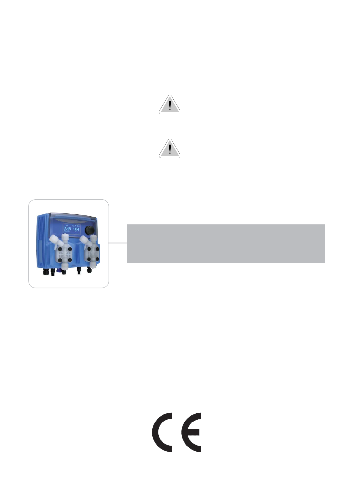
“WDPHCL” instrument complies with the following European regulations:
EN60335-1 : 1995, EN55014, EN50081-1/2, EN50082-1/2, EN6055-2, EN60555,3
Based on directive CEE 73/23 c 93/68 (DBT Low voltage directive) and directive 89/336/CEE (EMC
Electromagnetic Compatibility)
Instrument must be accessible at all times for both operating and servicing. Access must not be
obstructed in any way!
Feeder should be interlocked with a no-flow protection device to automatically shut-off the pumps when
there is no flow!
Pumps and accessories must be serviced and repaired by qualified and authorized personnel only!
Always discharge the liquid end before servicing the instrument!
Empty and rinse the liquid end before work on a pump which has been used with hazardous or
unknown chemicals!
Always read chemical safety datasheet!
Always wear protective clothing when handling hazardous or unknown chemicals!
Instrument must be operated / serviced by trained technicians only!
All connection operations must be performed while the instrument is not connected to main supply!

3
1. Introduction
WDPHCL is a fully Integrated All-in-One Swimming Pool Controller. Ideal for new construction projects the WDPHCL
innovates panel mount capability into a small wall-mount package.
2 Pumps for Chlorine and pH adjustment in PVDF, small-form-factor saves space, installation time, and shipping
expense.
It includes Input for a Flow Switch. Integral pumps can handle up to 20 bar and 16 l/h (Self-Venting Liquid-end as option),
high maintenance tubing sets and roller assemblies.
Working ranges are:
pH : from 0 to 14pH
Chlorine: from 0 to 10 mg/l
All information are provided through a large LCD display. Using a revolutionary wheel control the instrument can be easily
programmed. WDPHCL is housed in a IP65 plastic box.
2. The wheel
Located in the upper right side of WDPHCL there is a wheel that must be used to control the instrument. Wheel can be
rotated in both directions to scroll over the menus and / or pressed to confirm highlighted selection / value.
NOTE: Once changes are made press “OK” to save and exit from submenu. Press “ESC” to exit without saving.
Rotate wheel to scroll through menus or options
Press wheel to select highlighted option
Rotate wheel to scroll through menus or options
Press wheel to select highlighted option
SCROLL
SELECT

4
3. Mainboard Connections
Unplug instrument from main power supply then perform connections to probes and / or selected outputs by following
the above picture.
(A) STAND-BY input
(B) Flow input:
(C) pH Level input (left pump head)
(D) Cl Level input (right pump head)
(E) pH EPHS probe connector
(F) Cl ECL6 probe connector
(G) Power Supply: 230VAC 50-60 Hz.
(H)Alarm contact output:
Warning: Connections must be perfomed by qualified and trained personnel only.
LEFT PUMP HEAD (pH) RIGHT PUMP HEAD (Cl)
3 1
2 4
3 1
2 4
1 Blue (Ground)
2 Brown (+)
3 n/a
4 Black (Signal)
1 n/a
2 Black
3 Red
4 n/a
(A)
(H)
(D)
(F)
(E)
(C)
(G)
(B)

5
3.1 Hydraulic connections, hoses
Unplug instrument from main power supply then perform connections to probes and / or selected outputs by following the
above picture. Hydraulic connections are:
Suction Hose with level probe and foot filter
Delivery Hose with injection valve
Discharge Hose
Suction Hose.
Completely unscrew tightening nut from pump’s head and remove assembling
components: tightening nut, holding ring and pipe holder.
Assembly as shown. Insert hose into pipe holder until it reaches the bottom.
Lock hose on pump’s head by screwing down the tightening nut.
Use only hands to do it!
Connect other side of the hose to the foot filter using the same procedure.
Delivery Hose.
Completely unscrew tightening nut from pump’s head and remove assembling
components: tightening nut, holding ring and pipe holder.
Assembly as shown. Insert hose into pipe holder until it reaches the bottom.
Lock hose on pump’s head by screwing down the tightening nut.
Use only hands to do it!
Connect other side of the hose to the injection valve using the same
procedure.
Discharge hose.
Insert one side of discharge hose into pump head discharge connector.
Insert other side of discharge hose into product’s tank.
During priming procedure product exceeding will flow into tank.
Suction Hose
Tightening Nut
Holding Ring
Pipe Holder
O-ring
Valve

6
3.2 Hydraulic connections, level probes
Assembling foot filter with level probe.Level probe must be assembled with foot filter using the provided kit.
Foot valve is made to be installed into tank’s bottom without sediments priming problem.
Connect BNC from level probe into WDPHCL level inputs (“B” and “E” connectors).
Put level probe assembled with foot filter into tank’s bottom.
Warning: If there is a mixer installed into tank, install a suction lance instead of level probe / foot filter.
STEP 5
STEP 2
INSERT FLOATER
STEP 1
INSERT RING AS SHOWN
STEP 4
INSERT RING AS SHOWN
STEP 3
INSERT PROBE
WITH N.O. CONTACT
UNTIL TO HEAR
A CLICK

7
3.3 Hydraulic connections, pump heads
Injection Valve.
Injection valve must be installed on plant from water’s input.
Injection valve will open at pressure greater than 0,3bar.
Discharge hose (connector)
Discharge Knob
To Delivery hose
To Suction hose

8
4. Main Screen
When into normal operating mode, WDPHCL shows the following main screen:
UNITS (1)
VALUES (2)
PUMPS STATUS (3)
Main screen is divided int 3 zones.
(1) UNITS. “pH” is the measuring unit for pH probe.
“mg/l” is the measuring unit for Chlorine probe.
(2) VALUES These numbers are values read by the probes.
(3) PUMPS STATUS These fields are related to current pumps status and instrument activity.
DISPLAY EXPLANATION WHAT TO DO IF OCCURS
FEED ON Pump is dosing chemical product. No action required.
FEED OFF Pump is OFF. No action required.
LOW TANK Chemical product tank is almost empty. Check chemical tank. Restore correct level.
NO FLOW External flow contact stops both the pumps. Check flow.
OK Setpoint reached. No action required.
FEED LIMIT Time for dosing exceeded. Dosing alarm. Check pump dosing capacity.
PROBE FAIL Stuck reading values. Check probe for proper functioning.
DELAY Pump activity delayed. Countdown in progress. If not requested check PARAMETERS options.
WAIT PH pH priority dosage over Cl dosage. If not requested check PRIORITY options.
LEFT
PUMP HEAD
STATUS
RIGHT
PUMP HEAD
STATUS

9
5. Quick status check
From main screen rotate the wheel to review main instrument parameters and current status conditions.
Current time
Today date
Current pH reading
Current Chlorine reading
Dosing alarm condition
Probe failure status
NO FLOW contact status
Tank Level status
Last pH calibration result
Last pH calibration date
Last Cl calibration result
Last Cl calibration date

10
X5
6. Password
To grant access into “Main Menu” press the wheel from main screen and enter the passcode.
If this is the first time here then the passcode is 0000 (factory preset). Press wheel 5 times to enter into “Main Menu”.
Otherwise press the wheel 1 time and enter the passcode. Numbers can be selected rotating the wheel.
To set a new passcode choose “PARAMETERS” from “Main Menu” , move on “New Pcode”, click on wheel and enter a
four numbers code. Click on “EXIT” and choose “YES” to save request. The new passcode is now ready.
Lost passcode ?
Please dont’ forget the passcode (if changed). In the unfortunate event, please call your local distributor for unlocking procedure. There is no way for you to
recover lost passcode.

11
7. “Main Menu” list
To grant access into “Main Menu” enter the passcode (as described in previous chapter). Once into “Main Menu” rotate
the wheel to scroll through all the options available.
Set-Point (see page 12)
Calibration (see page 14)
Parameters (see page 20)
Pumps Activities (see page 21)
Instrument Reset (see page 22)
Max Strokes Settings (see page 22)
Dosing Alarm (see page 23)
International (see page 24)
Probe Failure (see page 25)
pH Compensation (see page 26)
Disinfectant (see page 26)
Flow (see page 27)
Service (see page 27)
Exit (to main screen)

12
8. “Set-Point”, pH (on/off)
pH reading values can be set to operate the pH pump using 2 set-points into On/Off mode or Proportional (%).
On/Off mode set the instrument to operate using two set values that enable or disable the pH pump. To use this
mode move cursor on “Working Mode”. Press the wheel and select it.
ON/OFF mode while dosingALKALI
Set pH value at 7.00 OFF and 6.90 ON.
Instrument will leave the pH pump active until reading value will increase up to 7.00pH.
At 7.00pH the pH pump will be disabled until reading value will decrease under 6.90pH.
Waiting Time: to let pump operate at pulses per minutes add one or more minute (1pulse every xx minutes). Otherwise (00 minutes) pump will
operate at set stroke settings (see page 22).
6.90 7.00
ON
OFF

13
8. “Set-Point”, pH (on/off)
ON/OFF mode while dosingACID
Set pH value at 7.00 OFF and 7.10 ON.
Instrument will leave the pH pump active until reading value will decrease up to 7.00pH
At 7.00pH the pH pump will be disabled until reading value will increase up to 7.10pH.
Waiting Time: to let pump operate at pulses per minutes add one or more minute (1pulse every xx minutes). Otherwise (00 minutes) pump will
operate at set stroke settings (see page 22).
To end procedure move cursor on “OK” and press wheel to proceed to “Save” request screen. Move wheel on “YES” to
save or “NO” to discard changes.
Do you know ?
In chemistry, an alkali is a basic, ionic salt of an alkali metal or alkaline earth metal element. Alkalis are best known for
being bases (compounds with pH greater than 7) that dissolve in water. The adjective alkaline is commonly used in English
as a synonym for base, especially for soluble bases. This broad use of the term is likely to have come about because
alkalis were the first bases known to obey the Arrhenius definition of a base and are still among the more common bases.
Since Brønsted-Lowry acid-base theory, the term alkali in chemistry is normally restricted to those salts containing alkali
and alkaline earth metal elements.
An acid (often represented by the generic formula HA [H+A−]) is traditionally considered any chemical compound that,
when dissolved in water, gives a solution with a hydrogen ion activity greater than in pure water, i.e. a pH less than 7.0.
That approximates the modern definition of Johannes Nicolaus Brønsted and Martin Lowry, who independently defined an
acid as a compound which donates a hydrogen ion (H+) to another compound (called a base). Common examples include
acetic acid (in vinegar) and sulfuric acid (used in car batteries). Acid/base systems are different from redox reactions in
that there is no change in oxidation state.
7.00 7.10
ON
OFF

14
8.1 “Set-Point”, pH (proportional)
pH reading values can be set to operate the pH pump using 2 set-points into On/Off mode or Proportional (%).
Proportional mode set the instrument to operate using a calculated percentage between two set values that
enable or disable the pH pump. To use this mode move cursor on “Working Mode”. Press the wheel and select it.
PROPORTIONAL mode between 7pH(0%) and 8pH (100%). [Stroke setting 180]
In this mode the pH pump will be “ON” for values greater than 8pH with maximum set strokes capacity (e.g.: 180) and
it’ll be “OFF” for values lower than 7pH. For values of 7.5pH pump will be “ON” with 90 strokes capacity. The calculation
is based on 180 strokes setting (see page 22). To end procedure move cursor on “OK” and press wheel to proceed to
“Save” request screen. Move wheel on “YES” to save or “NO” to discard changes.

15
8.2 “Set-Point”, Cl (on/off)
Cl reading values can be set to operate the Chlorine pump using 2 set-points into On/Off mode or Proportional (%).
On/Off mode set the instrument to operate using two set values that enable or disable the Chlorine pump. To
use this mode move cursor on “Working Mode”. Press the wheel and select it.
ON/OFF mode
Set Cl value at 0.80 mg/l ON and 1.00 mg/l OFF. The difference between the two Cl values is called HYSTERESIS.
Instrument will enable the Chlorine pump when reading value will decrease at 0.80mg/l
At 0.80mg/l the Chlorine pump will be enabled until reading value will increase at 1.00mg/l.
Waiting Time: to let pump operate at pulses per minutes add one or more minute (1pulse every xx minutes). Otherwise (00 minutes) pump will
operate at set stroke settings (see page 22).
0.80 1.00
ON
OFF

16
8.3 “Set-Point”, Cl (proportional)
Cl reading values can be set to operate the pH pump using 2 set-points into On/Off mode or Proportional (%).
Proportional mode set the instrument to operate using a calculated percentage between two set values that
enable or disable the Chlorine pump. To use this mode move cursor on “Working Mode”. Press the wheel and
select it.
PROPORTIONAL mode between 1.00Cl (0%) and 0.50Cl(100%). [Stroke setting 180]
In this mode the Cl pump will be “ON” for values lower than 0.50mg/l with maximum set strokes capacity (e.g.: 180)
and it’ll be “OFF” for values greater than 1mg/l. For values of 0.75mg/l pump will be “ON” with 90 strokes capacity. The
calculation is based on 180 strokes setting (see page 22). To end procedure move cursor on “OK” and press wheel to
proceed to “Save” request screen. Move wheel on “YES” to save or “NO” to discard changes.
To end procedure move cursor on “OK” and press wheel to proceed to “Save” request screen. Move wheel on “YES” to
save or “NO” to discard changes.

17
9. “Probe Calibration”, pH
pH calibration procedure involves two calibration points and it requires two buffer solutions. Default buffer solutions are
pH 4.00 and pH 7.00. pH reading value can be also 30°C temperature compensated from “pH compensation” menu.
From “Menu Calibration” choose “pH probe”.
In the following example instrument will calibrate pH using default buffer solutions values.
Note: this procedure assumes that instrument is correctly configured and a working pH probe connected.
Otherwise unattended results may occurr.
Calib 1st Point.
Once into “pH Calibration” menu move wheel on “P1” then press wheel to enter into first point calibration submenu.
Prepare 7.00pH buffer solution and dip probe’s sensor on it. Wait until reading value is stable and according to buffer
solution value move wheel until it is the same on display (“Cal. at” field). Default value is 7.00pH. To end procedure
move cursor on “OK” and press wheel to proceed to next step.
Note: buffer solution value may change if environment temperature it’s different than 20°C. Read solution’s
label for more information.According to this occurrence “pH Default” must be changed.
pH7
Power Supply calibration ?
To obtain the most reliable results during pulses calculation is possible to calibrate power supply read value. Press wheel on “P1” then move curso on “OK” and
confirm power supply read value. (e.g.: 230V).

18
9. “Probe Calibration”, pH
Calib 2nd Point.
Move wheel on “P2” then press wheel to enter into second point calibration submenu. Prepare 4.00pH buffer solution
and dip probe’s sensor on it. Wait until reading value is stable and according to buffer solution value move wheel until it
is the same on display (“Cal. at” field). Default value is 4.00pH.
To end procedure move cursor on “OK” and press wheel to proceed to “Save” request screen. Move wheel on “YES” to
save or “NO” to discard changes.
Note: buffer solution value may change if environment temperature it’s different than 20°C. Read solution’s
label for more information.According to this occurrence “pH Default” must be changed.
pH4

19
9.1 “Probe Calibration”, Cl
Cl calibration procedure involves probe’s selection, Zero (P1) and 2nd Point (P2) calibration. From “Menu Calibration”
choose “Cl probe”.
Note: This procedure assumes that instrument is correctly configured and a working Chlorine probe connected
and installed on system. Measurement must be performed using plant water. Otherwise unattended results
may occurr.
Calib Zero (P1).
Once into “Cl calibration” menu move on “P1” then press wheel to enter into
calibration mode. For a correct system calibration proceed as follows.
- install an “activated carbon filter” prior to probe’s holder.
- let system water flow into probe holder for about 30 minutes.
- press wheel (cursor must be on “Cal.at”). Remove filter.
Calib 2nd point (P2).
Now move on “P2” then press wheel to enter into calibration mode. For a correct system calibration use a Photometer
or a DPD device to read chlorine on system. Enter value using the wheel then move cursor on “OK”. Now press the
wheel.
Carbon Filter System
Photometer
To end procedure move cursor on “OK” and press wheel to proceed to “Save” request
screen. Move wheel on “YES” to save or “NO” to discard changes. If an error occurred
during calibration procedure then the instrument will show an error message and will ask
to proceed to a new calibration, cancel current operation or restore default settings.

20
10. “Parameters”
From “Menu Calibration” choose “Parameters”. This menu allows to set a delay (max 60 minutes) before pumps begin
to feed. Furthermore use this menu to set pH pump startup priority and to change default passcode.
Feeding Delay.
Move on “Feeding Delay” then press wheel. Choose a value between 0 (disabled) and 60 minutes (maximum delay
time). This feature can be used to accord a startup delay for the pumps. Delay occurs when instrument is powered or
after a “NO FLOW” contact recovery.
Mode.
Move on “Mode” then press wheel. If both pumps need to operate, a startup priority can be set to allow the pH pump to
begin to feed prior to Cl pump. Choose “pH priority” to enable this function. Cl pump will begin to dose when pH pump
has stopped.
New Pcode.
See page 10.
To end procedure move cursor on “OK” and press wheel to proceed to “Save” request screen. Move wheel on “YES” to
save or “NO” to discard changes.
Table of contents